Scholarship@Western
Scholarship@Western
Electronic Thesis and Dissertation Repository
12-14-2011 12:00 AM
Transition Metal Complexes with Reactive
Transition Metal Complexes with Reactive
Trimethylsilylchalcogenolate Ligands: Precursors for the
Trimethylsilylchalcogenolate Ligands: Precursors for the
Preparation of Ternary Nanoclusters
Preparation of Ternary Nanoclusters
Chhatra Bahadur Khadka
The University of Western Ontario
Supervisor
Prof. Dr. J. F. Corrigan
The University of Western Ontario Graduate Program in Chemistry
A thesis submitted in partial fulfillment of the requirements for the degree in Doctor of Philosophy
© Chhatra Bahadur Khadka 2011
Follow this and additional works at: https://ir.lib.uwo.ca/etd
Part of the Inorganic Chemistry Commons, and the Materials Chemistry Commons
Recommended Citation Recommended Citation
Khadka, Chhatra Bahadur, "Transition Metal Complexes with Reactive Trimethylsilylchalcogenolate Ligands: Precursors for the Preparation of Ternary Nanoclusters" (2011). Electronic Thesis and Dissertation Repository. 336.
https://ir.lib.uwo.ca/etd/336
This Dissertation/Thesis is brought to you for free and open access by Scholarship@Western. It has been accepted for inclusion in Electronic Thesis and Dissertation Repository by an authorized administrator of
Trimethylsilylchalcogenolate Ligands: Precursors for the
Preparation of Ternary Nanoclusters
(Spine title: Manganese containing Semiconductor Nanoclusters)
(Integrated-Article Format)
by
Chhatra B. Khadka
Graduate Program in Chemistry
A thesis submitted in partial fulfillment of the requirements for the degree of
Doctor of Philosophy
The School of Graduate and Postdoctoral Studies
The University of Western Ontario
London, Ontario, Canada
ii
The
University
of
Western Ontario, School of Graduate and
Postdoctoral Studies
Supervisor
Examiners
___________________________
__________________________
Dr. Ignacio Vargas Baca
Dr. John F. Corrigan
___________________________
Dr. Mahi Singh
___________________________
Dr. Philip A. W. Dean
___________________________
Dr. Nicholas C. Payne
The Thesis by
Chhatra Bahadur Khadka
entitled
Transition Metal Complexes with Reactive Trimethylsilylchalcogenolate
Ligands: Precursors for the Preparation of Ternary Nanoclusters
is accepted in partial fulfillment of the requirements for the degree of
Doctor of Philosophy
iii
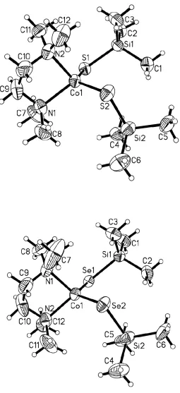
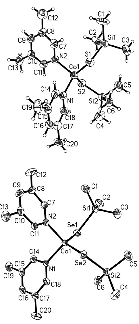
The Co2+and Mn2+complexes (N,N´-tmeda)Co(ESiMe3)2 (E = S, 1a; E = Se, 1b),
(3,5-Me2C5H3N)2Co(ESiMe3)2 (E = S, 2a; E = Se, 2b), [Li(N,N´-tmeda)]2[(N,N´
-tmeda)Mn5(µ-ESiMe3)2(ESiMe3)4(µ4-E)(µ3-E)2] (E = S, 3a; E = Se, 3b), [Li(N,N´
-tmeda)]2[Mn(SSiMe3)4] (4), [Li(N,N´-tmeda)]4[Mn4(SeSiMe3)4(µ3-Se)4] (5), and
[Li(N,N´-tmeda)]4[Mn(Se4)3] (6) have been isolated from reactions of Li[ESiMe3] and the
chloride salts of these metals. The treatment of (N,N´-tmeda)CoCl2 with two equivalents
of Li[ESiMe3] (E = S, Se) yields 1a and 1b, respectively, whereas similar reactions with
MnCl2 yield the polynuclear complexes 3a (E = S) and 3b (E = Se). The selective
preparation of the mononuclear complex 4 is achieved by increasing the reaction ratios of
Li[SSiMe3] to MnCl2 to 4:1. Single crystal X-ray analysis of 1−5, confirms the presence
of potentially reactive trimethylsilylchalcogenolate moieties and distorted tetrahedral
geometry around the metal centers in each of these complexes. These compounds could
potentially be utilized as a convenient source of paramagnetic ions for the synthesis of
ternary clusters.
The ternary clusters (N,N´-tmeda)6Zn14-xMnxS13Cl2 (7a-d) and (N,N´-tmeda)6Zn 14-xMnxSe13Cl2 (8a-d) and the binary clusters (N,N´-tmeda)6Zn14E13Cl2 (E= S, 9a; Se, 9b)
have been synthesized by reacting (N,N´-tmeda)Zn(ESiMe3)2 with Mn2+and Zn2+salts.
Single crystal X-ray analysis of the complexes confirms the presence of the six ‘(N,N´
-tmeda)ZnE2’ units as capping ligands that stabilize the clusters, and distorted tetrahedral
geometry around the metal centers. Mn2+ is incorporated into the ZnE matrix by substitution of Zn2+ions in the cluster core. Complexes 7a, 8a and 8d represent the first
iv
of Zn with Mn is perfectly feasible and at least partly allows for the identification of
some sites preferred by the Mn2+ metals. These calculations, combined with luminescence studies suggest a distribution of the Mn2+in the clusters. The room temperature emission spectra of clusters 7c-d display a significant red shift relative to the all zinc cluster 9a,
with a peak maximum centered at 730 nm. Clusters 8c-d have a peak maximum at 640
nm in their emission spectra.
The chalcogenolate complexes 3a and 4 have been utilized as molecular
precursors for the isolation of ternary nanoclusters, with approximate formulae
[Mn35/36Ag118/116S94(PnPr3)30], 10 and [Mn19/20Ag150/148S94(PnPr3)30], 11 respectively.Mn2+
is incorporated into the Ag2S matrix by substitution of two Ag+ions in the cluster core.
Keywords:
Nanocluster, ternary, quantum confinement, paramagnetic, chalcogen, chalcogenolate,
chalcogenide, X-ray crystallography, nanomaterials, photoluminescence, semiconductor,
silylated reagents, dilute magnetic semiconductor, quantum dot, doping, Group 6, Group
v
vi
Foremost, I would like to express my sincere gratitude to my supervisor Dr. John
F. Corrigan for all his patience, motivation, enthusiasm and important support throughout
this work. You have been a great teacher and have provided me with ample guidance
during my studies here. I cannot thank you enough for you kind support, all the
opportunities, constant encouragement and endless corrections of my thesis.
During my six long years at Western, I have had the privilege of meeting many
people. I thank them all for their friendship and support that have made those six years
fun and memorable. I would like to take this opportunity to thank all the graduate and
undergraduate students with whom I had the privilege of working with. I would like to
thank Siawash Ahmar, Taylor Battista, Aneta Borecki, Mahmood Fard, Diane Medeiros,
Brian Nikkel, Dr. Christian Nitschke, Bahar Khalili, Tetyana Levchenko, Dr. Dan
Macdonald, Dr. Deeb Taher and Dr. Elizabeth Turner. I owe a special thanks to Aneta
Borecki who taught me the all important Schlenk line and other techniques at the
beginning of my graduate studies and Dan for solving my crystal structures. Special
thanks go out to Siawash, Dan, Ashlee Howarth, Terry Lebold, Dave Dodd, Dwayne Dias
and Pellumb Jakupi for great friendship and all those memorable times we had over the
years.
I would like to thank the members of the Chemistry Staff that have provided
support during my graduate studies. Firstly, Yves Rambour, our glass blower, for all the
glassware he has made and repaired. I would like to thank the NMR facility, Matt
Willians, Chris Kirby and Kyle Pollard for their assistance with the NMR instruments.
vii
shops for meeting my requests for chemicals, keeping our glove boxes running properly
and taking care of our computers and other electrical equipment. I would also like to
thank our graduate coordinators present (Darlene McDonald) and past (Cheryl O’Meara)
for all their help.
I would like to take this moment to thank all the people who have made
contributions to this research. Dr. Annie K. Powell (KIT, Germany) is thanked for
allowing me to be a part of her lab during the ASPIRE exchange program and Dr.
Yanhua Lan (KIT, Germany) for her help with magnetic studies. Dr. Andreas Eichhöfer
(KIT, Germany) and Dr. Florian Weigend (KIT, Germany) are thanked for invaluable
suggestions, critical input and DFT calculations, respectively.Dr. Robert Hudson (UWO)
is thanked for allowing access to his fluorimeter. Dr. Mike Jennings and Dr. Guerman
Popov are thanked for their help with crystallography. I would also like to thank Dr.
Nick Payne (UWO) for teaching me X-ray crystallography and helping me with
crystallographic problems as well.
Finally, I have to give a special thanks to my family: although, I have been away
from them most of my life, I have always felt their love and support. Without their
never-ending support and constant encouragement, I would have never accomplished this.
viii
CERTIFICATE OF EXAMINATION ... ii
ABSTRACT ... iii
EPIGRAPH ... v
ACKNOWLEDGEMENTS ... vi
TABLE OF CONTENTS ... viii
CO-AUTHORSHIP ... xi
LIST OF TABLES ... xii
LIST OF FIGURES ... xiii
LIST OF SCHEMES ... xv
LIST OF APPENDICES ... xv
LIST OF ABBREVIATIONS ... xvii
CHAPTER ONE: INTRODUCTION ... 1
Manganese Doped Semiconductor Nanoclusters 1.1. Semiconductor Nanomaterials and the Quantum Confinement Effect .... 1
1.2. Optical Properties of Quantum Confined Nanoparticles ... 5
1.3. Doping in Quantum Dots ... 8
1.3.1. Electronic structure of Mn2+ in II-VI Semiconductor Lattice 9 1.3.2. Synthesis of Mn2+ doped II-VI semiconductor QDs ... 12
1.4. Molecular Precursor Route to Mn2+ Doped II-VI Nanoparticles ... 13
1.5. Molecular Precursor Route to Ternary MM’E Nanoclusters ... 15
1.5.1. Synthesis of Chalcogenolate Precursors ... 15
1.5.2. Reaction of Chalcogenolate Precursor with other Metal salts ... 17
1.6. Scope of the Thesis ... 19
1.7. References ... 21
CHAPTER TWO: ... 27
Trimethylsilylchalcogenolates of Co(II) and Mn(II): From Mononuclear Coordination Complexes to Clusters Containing –ESiMe3 Moieties (E= S, Se) 2.1. Introduction ... 27
2.2. Results and Discussion ... 28
2.2.1. Synthesis of Cobalt(II) Chalcogenolate Complexes ... 28
2.2.2. X-ray Crystallographic Structural Characterization ... 30
ix
2.3. Conclusions ... 49
2.4. Experimental Section ... 50
2.4.1. General Experimental ... 50
2.4.2. Syntheses... 52
2.4.2.1. Synthesis of (N,N′-tmeda)Co(SSiMe3)2, 1a ... 52
2.4.2.2. Synthesis of (N,N′-tmeda)Co(SeSiMe3)2, 1b ... 52
2.4.2.3. Synthesis of (3,5-Me2C5H3N)2Co(SSiMe3)2, 2a ... 53
2.4.2.4. Synthesis of (3,5-Me2C5H3N)2Co(SeSiMe3)2, 2b ... 53
2.4.2.5. Synthesis of [Li(N,N´-tmeda)]2 [(N,N´-tmeda)Mn5(SSiMe3)6(S)3], 3a ... 54
2.4.2.6. Synthesis of [Li(N,N´-tmeda)]2 [(N,N´-tmeda)Mn5(SeSiMe3)6(Se)3], 3b ... 54
2.4.2.7. Synthesis of [Li(N,N´-tmeda)]2[Mn(SSiMe3)4], 4 ... 54
2.4.2.8. Synthesis of [Li(N,N´-tmeda)]4[Mn4(SeSiMe3)4(Se)4], 5 ... 55
and [Li(N,N´-tmeda)]4[Mn(Se4)3], 6 ... 55
2.5. References ... 56
CHAPTER THREE: ... 59
Zinc Chalcogenolate Complexes as Molecular Precursors to Mn2+ Containing ZnE (E= S, Se) Nanoclusters 3.1. Introduction ... 59
3.2. Results and Discussion ... 61
3.2.1. Synthesis and Characterization of Chalcogenide Complexes ... 61
3.2.2. Photoluminescence Properties ... 71
3.3. Metal type Assignment by Quantum Chemical Calculations ... 77
3.4. Conclusions ... 85
3.5. Experimental Section ... 86
3.5.1. General Experimental ... 86
3.5.2. Syntheses... 88
3.5.2.1. Synthesis of [(N,N´-tmeda)6Zn12.3Mn1.7S13Cl2], 7a ... 88
3.5.2.2. Synthesis of [(N,N´-tmeda)6Zn10.9Mn3.1S13Cl2], 7b ... 88
3.5.2.3. Synthesis of [(N,N´-tmeda)6Zn10Mn4S13Cl2], 7c ... 89
3.5.2.4. Synthesis of [(N,N´-tmeda)6Zn6.2Mn7.8S13Cl2], 7d... 89
3.5.2.5. Synthesis of [(N,N´-tmeda)6Zn12Mn2Se13Cl2], 8a ... 90
3.5.2.6. Synthesis of [(N,N´-tmeda)6Zn10.8Mn3.2Se13Cl2], 8b ... 90
3.5.2.7. Synthesis of [(N,N´-tmeda)6Zn10.7Mn3.3Se13Cl2], 8c ... 91
3.5.2.8. Synthesis of [(N,N´-tmeda)6Zn8.2Mn5.8Se13Cl2], 8d ... 91
3.5.2.9. Synthesis of [(N,N´-tmeda)6Zn14S13Cl2], 9a ... 91
3.5.2.10. Synthesis of [(N,N´-tmeda)6Zn14Se13Cl2], 9b ... 92
x Containing Ag2S Nanoclusters
4.1. Introduction ... 98
4.2. Results and Discussion ... 100
4.2.1. Synthesis and characterization of [MnxAg188-2xS94(PnPr3)30], 10-11... 100
4.2.2. Optical Properties of MnAgS Clusters ... 111
4.3. Conclusions ... 114
4.4. Experimental Section ... 114
4.4.1. General Experimental ... 114
4.4.2. Syntheses... 116
4.4.2.1. Synthesis of [Mn36Ag116S94(PnPr3)30 ], 10 ... 116
4.4.2.2. Synthesis of [Mn20Ag148S94(PnPr3)30 ], 11 ... 116
4.4.2.3. Synthesis of [Ag188S94(PnPr3)30 ], 12 ... 117
4.5. References ... 118
CHAPTER FIVE: ... 122
Summary and Future work 5.1. Summary ... 122
5.2. References ... 126
APPENDIX A: ... 127
X-ray Crystallographic Data Parameters and Atomic Positions For Compounds 1-10 APPENDIX B: ... 161
xi
Chapter 2 was based on a manuscript authored by Chhatra Khadka, Daniel
MacDonald, Yanhua Lan, Annie Powell, Dieter Fenske and John Corrigan. All the
experimental work and majority of writing was performed by Chhatra Khadka with the
exception of X-ray crystallographic analyses which were performed by Daniel
Macdonald and John Corrigan. The magnetic studies (Section 2.2.2.3.1) were performed
together with Annie Powell and Yanhua Lan at KIT, Karlsruhe, Germany.
Chapter 3 was based on a manuscript authored by Chhatra Khadka, Andreas
Eichhöfer, Florian Weigend and John Corrigan. All the experimental work and majority
of writing was performed by Chhatra Khadka and X-ray crystallographic analyses which
were performed by John Corrigan. The DFT calculations (Section 3.3) were performed
xii
Table 2.1. Selected bond lengths (Å) and Angles (º) for Complexes 1-2 ... 34
Table 2.2. Selected bond lengths (Å) and Angles (º) for Complexes 3a, 3b . 38 Table 2.3. Selected bond lengths (Å) and Angles (º) for Complex 4... 40
Table 2.4. Selected bond lengths (Å) and angles (º) for Complex 5 ... 43
Table 2.5. Selected bond lengths (Å) and Angles (º) for Complex 6... 45
Table 3.1. Selected bond lengths (Å) Complexes 9a, 9b ... 64
Table 3.2. Selected bond Angles (º) for Complexes 9a, 9b ... 66
Table 3.3. Atomic ratio of Zinc and Manganese using ICP-AES 7-8 ... 68
Table 3.4. Selected bond lengths (Å) and angles (º) for Complex 8d ... 70
Table 3.5. Frequency (%) of Mn found at positions 1-8 for isomers that are higher in energy than the most stable one of each composition by less than 3 kJ/mol ... 83
Table 3.6. Most favorable isomers for each composition, 7-8 ... 84
Table 4.1. X-ray Crystallographic Data parameters for Complex 10 ... 106
Table 4.2. Atomic ratio of Mn:S:Ag obtained using EDX analyses for 10 and 11 ... 109
Table 4.3. Molecular formula calculated using the metal ratio from ICP-AES, 10 and 11 ... 110
xiii
Figure 1.1. Schematic representation of the electronic structure of
bulk semiconductors, quantum dot and molecule ... 3
Figure 1.2. Schematic diagram representing the origin of band-edge
and deep trap emissions ... 6
Figure 1.3. Representative normalized photoluminescence spectra of
typical II-VI thiol-capped nanocrystals ... 7
Figure 1.4. Tanabe-Sugano ligand field energy level diagram for
Mn2+ (d5) in a cubic ligand field ... 10
Figure 1.5. Schematic illustration of non-radiative and radiative
relaxation process in Mn2+ doped II-VI QDs ... 11
Figure 1.6. Molecular structure of the cluster [Cd4Mn6Se4(SePh)12(PnPr3)…14
Figure 1.7. Some examples of M-ESiMe3 complexes used as precursor
for MM′E cluster synthesis………...16
Figure 1.8. Molecular structure of Hg15Cu20Se25(PnPr3)18 ... 18
Figure 1.9. Molecular structure of (tmeda)5Zn5Cd11Se13(SePh)6 ... 18
Figure 2.1. The molecular structure of (N,N´-tmeda)Co(SSiMe3)2, 1a and
(N,N’-tmeda)Co(SeSiMe3)2, 1b ... 31
Figure 2.2. The molecular structures of, (3,5-Me2-C5H3N)2Co(SSiMe3)2, 2a
and (3,5-Me2-C5H3N)2Co(SeSiMe3)2, 2b ... 32
Figure 2.3. Molecular structure of [Li(N,N´-tmeda)]2
[(N,N´-tmeda)Mn5(µ-SSiMe3)2(SSiMe3)4(µ4-S)( µ3-S)2], 3a ... 36
Figure 2.4. The Mn5Se9 framework in the molecular structure of
[(N,N´-tmeda)Mn5(µ-SeSiMe3)2(SeSiMe3)4(µ4-Se)(µ3-Se)2]2−,3b 37
Figure 2.5. Molecular structure [Li(N,N´-tmeda)]2[Mn(SSiMe3)4], 4 ... 39
Figure 2.6. Molecular structure of [Li(N,N´-tmeda)]4
[Mn4(SeSiMe3)4(µ3-Se)4], 5 ... 41
xiv
Figure 2.9. Plots of χT vs T (top) andM vs H (bottom) for Complex 5 ... 48
Figure 3.1. Molecular structure of [(N,N´-tmeda)6Zn14E13Cl2], 9a ... 63
Figure 3.2. The stereo pair images of [(N,N´-tmeda)6Zn14E13Cl2], 9a-b ... 67
Figure 3.3. Molecular structure of [(N,N´-tmeda)6Zn10Mn4Se13Cl2], 8d ... 69
Figure 3.4. Normalized room temperature solution state UV-visible absorption, photoluminescenece excitation (PLE) and photoluminescence (PL), 9a, 7a and 7d ... 72
Figure 3.5. Normalized room temperature solution state UV-visible absorption, photoluminescence excitation (PLE) and photoluminescence (PL),9b, 8a and 8d ... 74
Figure 3.6. Normalized room temperature solid state photoluminescence (PL),9a, 8a and 8d ... 76
Figure 3.7. (N,N´-tmeda)6Zn14-xMnxS13Cl2. The eight positions labeled by numbers are occupied by either Mn or Zn ………79
Figure 3.8. Estimated relative energies versus explicitly calculated energies for selected isomers of Zn10Mn4 ... 82
Figure 4.1. Dynamic light scattering measurements of 10 and 11 ... 102
Figure 4.2. Depiction of the polyhedra defined by sulfide ligandsin12 ... 104
Figure 4.3. Molecular structure and space filling model of 10 ... 105
Figure 4.4. Disordered core of compound 10 ... 108
Figure 4.5. Picture of single crystals of 10 ... 108
Figure 4.6. EDX spectrum of cluster[Mn35/36Ag118/116S94(PnPr3)30], 10 ... 109
xv
Scheme 1.1. General outline of the reaction of M-ESiR3 complexes with
M′Xn salts in the formation of M-E-M′ bridging interactions…. 15
Scheme 2.1. Synthesis of(N,N´-tmeda)Co(ESiMe3)2 and
(3,5Me2C5H3N)2Co(ESiMe3)2 ………..28
Scheme 3.1. Synthesis of (N,N´-tmeda)6Zn14-xMxE13Cl2 (7a-9b ... 61
LIST OF APPENDICES
Appendix A.1. Crystal data and structure refinement for
(N,N′-tmeda)Co(SSiMe3)2 1a ... 128
Appendix A.2. Crystal data and structure refinement for
(N,N′-tmeda)Co(SSiMe3)2 1b ... 130
Appendix A.3. Crystal data and structure refinement for
(3,5-Me2-C5H3N)2Co(SeSiMe3)2 2a ... 132
Appendix A.4. Crystal data and structure refinement for
(3,5-Me2-C5H3N)2Co(SeSiMe3)2 2b... 134
Appendix A.5. Crystal data and structure refinement for [Li(N,N´-tmeda)]2
[(N,N´-tmeda)Mn5(SSiMe3)2(SSiMe3)4(µ4-S)(µ3-S)2], 3a ... 136
Appendix A.6. Crystal data and structure refinement [Li(N,N´-tmeda)]2
[(N,N´-tmeda)Mn5(SeSiMe3)2(SeSiMe3)4(µ4-Se)(µ3-Se)2], 3b 138
Appendix A.7. Crystal data and structure refinement for
[Li(N,N´-tmeda)]2[Mn(SSiMe3)4], 4 ... 140
Appendix A.8. Crystal data and structure refinement for
[Li(N,N´-tmeda)]4[Mn4(SeSiMe3)4(µ3-Se)4], 5 ... 142
Appendix A.9. Crystal data and structure refinement for
[Li(N,N´-tmeda)]4[Mn(Se4)3], 6 ... 144
Appendix A.10. Crystal data and structure refinement for
(N,N´-tmeda)6Zn12.3Mn1.7S13Cl2 , 7a ... 146
Appendix A.11. Crystal data and structure refinement for
xvi
Appendix A.13. Crystal data and structure refinement for
(N,N´-tmeda)6Zn8.2Mn5.8S13Cl2 , 8d ... 152
Appendix A.14. Crystal data and structure refinement for
(N,N´-tmeda)6Zn14S13Cl2 , 9a ... 154
Appendix A.15. Crystal data and structure refinement for
(N,N´-tmeda)6Zn14Se13Cl2 , 9b ... 156
Appendix A.16. Crystal data and structure refinement for
Mn35/36Ag116/118S94(PnPr3)30], 10 ... 158
Appendix B.1. Plots of χT vs T (top) andM vs H (bottom) for Complex 3b . 161
Appendix B.2. Normalized room temperature solution state UV-visible absorption,
photoluminescenece excitation (PLE) and
photoluminescence (PL), 7b and 7c... 162
Appendix B.3. Normalized room temperature solution state UV-visible absorption,
photoluminescenece excitation (PLE) and
photoluminescence (PL),8b and 8c... 163
Appendix B.4. Quantum chemical calculations data for 7-8 ... 164
xvii
µL ... microliter °C ... degree Celsius Å ... angstrom
AES ... atomic emission spectroscopy B ... Racah parameter
CB ... conduction band
CCDC ... Cambridge Crystallographic Datacentre
DCM ... dichloromethane
DFT ... density functional theory DLS ... dynamic light scaterring DMF ... dimethylformamide
DMS ... dilute magnetic semiconductor DMSO ... dimethylsulfoxide
E ... chalcogen (S,Se,Te)
E ... energy
EDX ... energy dispersive X-ray Et ... ethyl
eV ... electron volts g... gram
H ... magnetic field
Hex ... hexyl
HOMO ... highest occupied molecular orbital
ICP ... inductively coupled plasma
iPr ...
iso-propyl
IR... infrared K ... Kelvin
LED ... light emitting diode
LUMO ... lowest unoccupied molecular orbital
M ... d-block metal atom
M ... magnetization
Me ... methyl
min ... minute mL ... millilitre mm ... millimetre mmol ... millimole
nBu...
n-butyl
nm ... nanometer
nPr ...
n-propyl
OAc ... acetate
Oe ... Oerstad
Ph ... phenyl
PL ... photoluminescence PLE ... photoluminescence excitation
ppm ... parts per million Py ... pyridine
QD ... quantum dot R ... organic side group
SQUID ... superconducting quantum interference device
St ... sterate T ... temperature
t
B ... tert-butyl
THF ... tetrahydrofuran TMEDA ... tetramethyl
ethylenediamine
UV ... ultraviolet UV ... ultraviolet
VB ... valence band Vis ... visible
∆ ... Crystal field splitting
parameter
µB ... magnetic moment
χ ... magnetic
susceptibility
CHAPTER ONE
INTRODUCTION: MANGANESE DOPED SEMICONDUCTOR NANOCLUSTERS
1.1. Semiconductor Nanomaterials and the Quantum Confinement Effect
Nanomaterials are a class of materials having at least one dimension in the range
of 1-100 nm. As such, their size is intermediate between a typical molecule and extended
bulk solids. Nanomaterials continue to attract significant research interest from multiple
scientific disciplines, which can be attributed to their unique size-dependent
optoelectronic, magnetic and catalytic properties, phenomena not observed in bulk solids
or molecular materials.1-8 Understanding the properties of nanomaterials and exploring their potential applications are the two major driving forces behind the synthesis of a
large variety of nanomaterials with diverse physiochemical properties. Magnetic
nanomaterials of transition metals and transition metal oxides (e.g. Mn, Co, Fe3O4)9,10
have proven to be useful in various biomedical applications.11 The possibility of designing catalysts with high activity, greater selectivity and high stability by tailoring
the size, shape, morphology and composition of nanomaterials has led to an emerging
field of ‘nanocatalysts’.12-14 Amongst nanomaterials, semiconductors represent the most extensively studied class. Semiconductors are a class of materials which have
conductivity values between those of conductors (metals) and insulators (glass) and
whose band gap energies typically lie between 0.5 to 3.5 eV.15 The characteristic feature of a semiconductor is its intrinsic band gap (Eg), the energy that separates the filled
pure elements (eg. Si, Ge), binary compounds (eg. GaAs, CdSe) and ternary compounds
(eg. ZnxCd1-xSe, HgxCd1-xTe).
When electrons absorb energy greater than that of the band gap of the
semiconductor, they are excited across the band gap and into the conduction band. This
transition creates a positively charged hole in the valence band and leads to the formation
of an electron-hole pair, known as an exciton. The separation of an optically excited
electron-hole pair is referred to as the excitonic Bohr radius, which is on the order of a
few nanometers in semiconductors. The electron-hole pair can recombine releasing
energy, often as a photon, approximately equal to the band gap of the material. This
process is called a radiative recombination. Alternatively, an exciton can recombine
non-radiatively without releasing a photon. The energy is often released through lattice
vibrations or heat and is usually caused by defects in the crystal lattice or surface
defects.16
As the size of semiconductor crystals becomes small enough that it approaches
the size of the material’s exciton Bohr radius, the exciton is confined by the dimension of
the crystal, causing the nanomaterials to exhibit a quantum confinement effect.1,8 A nanomaterial can be quantum confined along one, two or all three dimensions. A
quantum well describes the system confined in one dimension while a system confined in
two dimensions is called quantum wire. A system confined in all three dimensions is
called a quantum dot (QD). Well defined semiconducting quantum dots are the subject of
this thesis. Colloidal quantum dots are made by organometallic chemical methods and
Brus being recognized as a pioneer in this field.18a As the nanomaterials are reduced to the quantum confined size regime, the electronic energy levels can no longer be treated as
continuous, as in a bulk semiconductor, but rather the quantization of energy levels
occurs together with an increase in the band gap energy with decreasing particle size
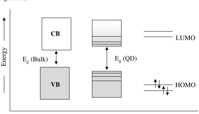
(Figure 1.1).
Figure 1.1. Schematic representation of the electronic structure of bulk semiconductors
(left), quantum dot (middle) and molecules (right) showing the band gap (Eg).18b
For each of the energy levels, the electronic state could be described by an
atom-like wave function, that is, a probability distribution in space and time similar to the
electrons bound to the nucleus. For this reason, quantum confined semiconductors are
also called ‘artificial atoms’. In a bulk semiconductor, the dimensions of the system are
essentially infinite compared to the dimensions of the carriers (negative electrons and
positive holes). The wave functions, which are the standing waves in the materials, are
spread over an infinite number of unit cells. Confinement in three dimensions based on
the physical size of the material changes the boundary conditions imposed on the wave
HOMO LUMO
E
ne
rgy
VB CB
Eg(QD)
function resulting in a transformation in the electronic structure from the continuous
density of states in the bulk to the discrete levels in a quantum dot. The discrete structure
of energy states leads to the discrete absorption observed in the absorption spectrum of
the quantum dots, which is in contrast to the continuous spectrum of a bulk
semiconductor. This is analogous to the ‘particle in a box’ model which predicts that the
size dependent contribution to the energy gap is simply proportional to 1/R2. The energy
associated with an electron and a hole pair in quantum dot is given by equation 1.1,
derived using the parabolic band model, where ER is the lowest excited state energy of
the nanoparticle, Eg is the band gap energy of the bulk semiconductor, ħ is the reduced
Planck’s constant, R is the radius of the particle and me and mh are the effective masses of
the electron and hole, respectively.
(1.1)
A more accurate correlation between the excitation energy and the particle size warrants
the inclusion of the coulombic interaction that exists between the charge carriers in these
confined sytems. The appropriate relationship as proposed by Efros and Efros,18a Brus19 and Kayanuma20 is thus obtained by modifying equation 1.1 to account for the coulombic interaction and is given in equation 1.2.
(1.2)
The coulombic interaction of an exciton is accounted by the second term in the equation
1.2 where ε is the dielectric constant of the semiconductor, while the third term is a
+
+
=
h e g Rm
m
R
E
E
1
1
2
2 2 2π
h
* 2 2 2 2 248 . 0 8 . 1 1 1 2 Ry h e g R E R e m m R EE − −
spatial correlation correction (ERy* is the effective Rydberg energy). The latter term is not
dependant on size and is typically very small, but may become significant for materials
with a small dielectric constant. Besides effective mass approximation approach,
empirical pseudopotential approach and tight-binding models are also used to gain
reasonable estimation of the relationship between the excitonic energy with decreasing
particle size in these quantum confined systems.21
1.2. Optical Properties of Quantum Confined Nanoparticles
The optical properties of semiconducting nanomaterials are strongly affected by
their surface characteristics due to the presence of a higher fraction of surface atoms as
the particle sizes decreases.22 Due to the consequence of quantum confinement, the particle size distribution of these nanomaterials has a significant impact on the optical
properties. These effects can be observed in the emission spectra using
photoluminescence (PL) spectroscopy. Photoluminescence of quantum dots can occur as
either band edge PL or deep trap PL emission (Figure 1.2).23 The capping of QD with organic ligands provides ‘electronic’ passivation by terminating dangling bonds present
on the surface. The unterminated dangling bonds can affect the QD emission efficiency
leading to a loss mechanism wherein electrons are trapped at the surface before emitting a
photon. Band edge emission occurs from the recombination of the exciton from the
shallow trap and is usually only slightly red shifted from the absorption energy with a
narrow band width. On the other hand, the deep trap emission is characterised by a broad
Figure 1.2. Schematic diagram representing the origins of band-edge (left) and deep trap
emissions (right).23
It is essential to control the surface chemistry of QDs to understand the direct
interrelation between the nanocrystals and their unique physical and chemical properties.
The surface passivation of QDs is usually carried out by using surface bound organic
ligands or a secondary inorganic shell, which are capable of effectively eliminating the
surface defect sites. It is well established that certain ligands (phosphines, phosphine
oxides, amines, thiols) can be effectively used to reduce the surface defects, thereby
enhancing the band-edge emission. On the other hand, growth of a secondary shell of a
material with higher band gap energy than that of the core material introduces physical
barrier between the surface ligands and the core eliminating the surface defects. A variety
the probability of electron-hole recombination by localizing the exciton on the discrete
valence and conduction band energy levels.24-26 The synthesis of surface passivated monodisperse quantum dot is achieved via variety of synthetic pathways but the pyrolysis
of metal-organic precursors in hot coordinating solvents (120-360°C) is the most
successful in terms of monodispersity of the nanoparticles.28 These preparative routes involve a temporally discrete nucleation event followed by relatively rapid growth from
solution-phase and finally slower growth by Ostwald ripening. The disappearance of
broad red shifted deep-trap emission and enhancement of sharp band-edge emission are
indicative of effective passivation of the surface (Figure 1.3).29
Figure 1.3. Representative normalized photoluminescence spectra of typical II-VI
More problematic and an area that has received less attention, however, has been
the goal of controllably incorporating atomic impurities into semiconducting quantum
dots. This technique is also known as doping. It is well known from present
semiconductor technologies that the incorporation of impurities (dopants) or defects into
semiconductor lattices is the primary means of controlling electrical conductivity, and
may also have an immense effect on the optical, luminescent, magnetic, or other
physical properties of the semiconductor.30 Thus, doping is a critical step for tailoring properties for specific applications and to gain fundamental scientific understanding of
the doping process in nanoparticles.
1.3. Doping in Quantum Dots
Doping semiconductor quantum dots with desired atomic impurities allows the
possibility of tuning the emission to longer wavelengths that otherwise could not be
possible from their undoped bulk counterparts.31 Doped QD can also be used to impart magnetic functionality into the semiconductor for the development of magneto-optical
materials, whose optical properties can be tuned by an external magnetic field making
them a potential candidate for spintronic applications. Spintronics (spin based
electronics) will add the spin degree of freedom to conventional semiconductor
charge-based electronics thereby enhancing the capability and performance of the electronic
product. The potential advantages of these new devices could be increased processing
speed and improved power efficiency compared with conventional semiconductor
attracted significant interest due to their potential applications as well as fundamental
physical properties.33−45 This is due to the unique size specific magnetic and optical properties, such as the giant Zeeman splitting of electronic states and carrier-induced
ferromagnetism, that arises from the coexistence of the quantum confinement effect and
its influence on the sp-d exchange interactions between magnetic ions and the
semiconducting host.32,44,60 Doped QD not only retain all the advantages of QD, but can also eliminate the self-quenching from non-radiative recombinations. The energy of the
excitons can be efficiently transferred to the dopant centres, suppressing undesirable
radiation pathways, resulting in higher quantum yield combined with narrow emission
line width.46
Mn2+is by far the most commonly used dopant and it acts both as luminescent center and localized spins in semiconductor nanoparticles.30,46 Mn2+ doped semiconductors have comparable emission efficiency as their undoped counterparst and
can also have better thermal, chemical and photochemical stability.36,44 Further exploration into these robust and efficient emitters could lead to applications such as
lasers,47 light emitting diodes,48 and in bioimaging.34 Furthermore, as a source of magnetic centers, they have potential to find application in optics and
magneto-electronic devices.49
1.3.1. Electronic Structure of Mn2+ in II-VI Semiconductor Lattice
The local electronic structure of Mn2+ ions a in II-VI semiconductor crystal lattice has been successfully described by ligand field theory.50-52 In the high spin state, Mn2+,
fold spin degeneracy (6S). The tetrahedral or pseudo-tetrahedral cation geometries in a II-VI semiconductor lattice removes the five fold degeneracy of the 3d orbitals into a three
fold degenerate t2 set (dxy, dyz and dxz) and a two fold degenerate e set (dx2-y2, dz2). The
energy difference between the more stable e and less stable t2 set for a given cation
depends on the crystal field splitting parameter. The splitting of the free ion ground state,
as interpreted using a simplified Tanabe-Sugano diagram (Figure 1.4) for Mn2+, gives rise to the ground state 6A1 and the lowest-energy excited state. 4T1. The 4T1→6A1 ligand field
transition (Figure 1.4) is responsible for the characteristic luminescence of Mn2+ ions into doped II-VI semiconductor lattices.46
Figure 1.4. Tanabe-Sugano ligand field energy level diagram for Mn2+ (d5) in a cubic
ligand field, showing several spin forbidden lowest ligand field excited states, and indicating the emissive 4T1→6A1 transition (orange arrow) observed in many Mn2+ doped
Although the spin selection rule forbids the 4T1→6A1 transition, it is partially overcome
by the spin-orbit coupling at the Mn2+ and to a lesser extent at the coordinated anions.54 At higher Mn2+ concentrations, exchange interactions between Mn2+−Mn2+ also provide a mechanism that circumvents the spin forbiddness because the transition only needs to
conserve the total spin of the “cluster”.55,56 The dynamics of electron-hole recombination in most Mn2+ doped II-VI semiconductor systems can be described based on the processes illustrated in Figure 1.5.
Figure 1.5. Schematic illustration of non-radiative (curly arrow) and radiative (straight
arrow) relaxation process in Mn2+ doped II-VI QDs.46 Reproduced with permission from
Elsevier.
When an electron in the valence band of the Mn2+ doped II-VI host undergoes photo-excitation, it subsequently is transferred to the 4T1 state. Following electron
transfer, internal relaxation to the 4T1 state occurs rapidly because of the large density of
orbital of Mn2+. The 4T1→6A1 ligand field excitation energy (~ 2.1eV) is characteristic of
Mn2+ doped II-VI semiconductors that have higher band gap energy than 2.1eV. Although the luminescence intensity of Mn2+ doped QDs varies with temperature and distribution of dopants, the energy transfer to Mn2+ which is very fast relative to excitonic emission, plays a vital role in the enhanced luminescence intensity observed in these
systems.46
1.3.2. Synthesis of Mn2+ Doped II-VI Semiconductor QDs
The importance of doping in bulk semiconductors has stimulated research efforts
to develop synthetic methods to incorporate magnetic dopants into semiconducting
nanoparticles. To date, a variety of semiconductor hosts have been doped with Mn2+ together with other magnetic impurities. The main challenge in the synthesis of doped
QDs has been to introduce the impurity in the core (not on the surface or interface) of the
nanoparticle without compromising the high crystallinity, monodispersity and well
controlled size.57 Most of the best characterized doped QDs investigated to date have been prepared using physical methods like molecular beam epitaxy, lithography and
related techniques.58-61 Along with the physical methods, chemical methods for the synthesis of analogously doped QDs have advanced considerably in recent years.62-64 The rapid exploration of a different experimental parameters (composition, size, shape etc.),
easy processibility, scale-up capacity and the possibility of synthesizing unique
heterostructures that the physical methods cannot are some of their advantages.46,65 With a brief overview of the literature, it becomes evident that molecular precursor
most commonly used chemical synthetic strategies.28,46,62-64 Although much progress has been made in the synthesis of doped QDs by chemical routes, there are still some
puzzling questions. It remains difficult to incorporate Mn2+ into semiconductors (<6 nm) beyond 1-2% despite the high bulk solubility of these ions.29,66 To this day, reports on a complete and accurate structural characterization of the local environment of the
magnetic ions within the semiconductor host is minimal.38,67 The accurate structural characterization of doped QDs is vital to gain insights into the unique phenomena that
occur in quantum confined Mn2+ doped semiconductors and to establish structure property relationships. Almost all of the doped semiconductors studied to date are
nanoparticles. As such, they are usually less well characterized and are often associated
with a certain degree of size distribution. Although, there exists no distinct differentiation
between the terms nanoparticle, nanomaterial and nanocluster in the literature,
nanoclusters are considered (in this thesis) as nanoscale materials whose composition and
structure can be determined accurately using X-ray crystallography. The synthesis of
Mn2+ containing semiconductor nanoclusters could provide alternative synthetic techniques that would add to the ever growing knowledge of doping semiconductors at
the nanoscale.
1.4. Molecular Precursor Route to Ternary Mn2+ Doped II-VINanoparticles
The molecular precursor approach to synthesize Mn2+ doped II-VI nanoparticles was first employed by the O’Brien group, who prepared Mn2+ doped ZnS and CdS by thermolysis using Zn(S2CNEt2)2 or Cd(S2CNMenHex)2 as precursors in the presence of
precursor in the presence of MnCl2 to obtain Mn2+ doped CdSe nanoparticles via cluster
thermolysis.42 Colliodal Mn2+:CdSe nanoparticles were synthesized in a thermolysis reaction using [Cd4(SPh)10]2- in the presence of MnCl2 and elemental selenium.69
Similarly, Mn2+:ZnSe nanoparticles have been prepared by the use of [Zn4(SPh)10]2- as
molecular precursor in the presence of MnCl2 salt and elemental selenium.70
[Zn10Se4(SPh)16]4- has also been used in presence of Mn(stearate)2 to obtain Mn doped
ZnSe nanowires.71 Despite the developments in preparation of Mn2+ doped II-VI nanoparticles employing different transition metal chalcogen complexes as precursors,
analogous nanoclusters of these systems have received little attention. To our knowledge,
the only published Mn2+ doped II-VI nanoclusters reported to date are [Cd4Mn6Se4(SePh)12(PPr3)4] (Figure 1.6) and [Cd4Mn4S(SePh)14(PPr3)2] obtained using
Cd(N(SiMe3)2) and Mn(N(SiMe3)2) as precursors in the presence of PhSeH and the
addition of Se(SiMe3)2.72
Figure 1.6. Molecular structure of the cluster [Cd4Mn6Se4(SePh)12(PnPr3)4].72 C and H
1.5. Molecular Precursor Route to Ternary MM′E (E= S, Se,Te) Nanoclusters
Previous works have proven that transition metal complexes coordinated with a
silylchalcogenolate ligand represent practical precursors for synthesis of polynuclear
MM′E nanoclusters.73-80 The principle of this designed methodology is focused on the
synthesis of metal complexes with pendant reactive trimethylsilylchalcogenolate ligands.
The –ESiMe3 moieties of these complexes undergo substitution reactions with other
metal salts leading to the formation of ternary MM′E as outlined in Scheme 1.1 below.
Scheme 1.1. General outline of the reaction of M-ESiR3 complexes with M′Xn salts in the
formation of M-E-M′ bridging interactions (M, M′ = d-block metals).77
1.5.1. Synthesis of Chalcogenolate Precursors
The use of silylated chalcogen reagents (RESiMe3 and E(SiMe3)2) in metal
chalcogen nanocluster synthesis has been well developed by Fenske and coworkers.79 These species react readily with a wide range of metal salts including main group and
transition metals to form either metal chalcogenide (M-E-M′) or metal chalcogenolate
(M-ER) bonding interactions. The driving force for the reaction is the thermodynamically
favorable formation of an X-Si bond and the elimination of XSiMe3 (X= halide, acetate
etc.). The synthesis of low nuclearity transition metal chalcogenolate complexes is
coordination modes, thus leading to the formation of polymeric structures or infinite
lattice structures. Typical strategies to overcome this tendency involve the use of
sterically demanding (“bulky”) substituents ‘R’ on the chalcogenolate group and/or
additional, strongly donating or chelating ancillary ligands around the metal centres.79 The incorporation of large ligands to increase the steric bulk can prohibit further
reactivity of these complexes. Thus, a delicate balance is needed to isolate M-ESiR3
complexes in which the pendant -SiR3 groups are still reactive.79 The rationale for the
synthesis of silyl-functionalized metal chalcogenolate is that the E-Si bonds are
substantially weaker and can be more readily cleaved than E-C bonds. The elimination of
the pendant –SiR3 can be readily induced by reacting M-ESiR3 complexes with M′Xn
salts leading to M-E-M′ bridging interactions via elimination of XSiR3. Some of the
mononuclear transition metal chalcogenolates previously synthesized in the Corrigan
laboratories that have been utilized as precursors for ternary nanocluster synthesis are
shown in Figure 1.6.
M N
N
ESiMe3
ESiMe3
M= Zn, Cd
Zn N
N
ESiMe3
ESiMe3
Cu
R3P
ESiMe3 R3P
R3P
R= Et, nPr
Figure 1.7. Some examples of M-ESiMe3 complexes used as precursor for MM′E cluster
1.5.2. Reaction of a Chalcogenolate Precursor with Other Metal Salts
The utility of the precursors complexes, (nPr
3P)3Cu(ESiMe3) (E = S, Se) for the
synthesis of nanoscopic ternary clusters is demonstrated by the isolation of
[Hg15Cu20E25(PnPr3)18].73a The principle of this approach is based on the reactivity of the
−SiMe3 moiety, which can be exploited to promote the formation of Cu-E-Hg bonding
interactions. Single crystal X-ray crystallographic analysis reveals the ‘pinwheel-shaped’
clusters [Hg15Cu20E25(PnPr3)18] (E = S, Se) in which the three core elements are
intimately mixed within the structure as shown in Figure 1.8. Similarly, [ZnxCd 10-xE4(EPh)12(PnPr3)4]75 (E= Se, Te; x= 2, 3), and [Cu9Ag3S6(PEtPh2)8]80 have been
synthesized using (3,5-Me2C5H3N)2Zn(ESiMe3)2 and (PEtPh2)3Cu(SSiMe3), respectively.
(N,N´-tmeda)Zn(SeSiMe3)2 has also previously been utilized as a molecular precursors
for the synthesis of the ternary nanocluster, [(N,N´
-tmeda)5Zn5Cd11Se13(SePh)6(THF)2].76b The molecular structure of this compound is
Figure 1.8. Molecular structure of Hg15Cu20Se25(PnPr3)18. The carbon atoms of the
phosphine ligands are omitted for clarity.73a
Figure 1.9. Molecular structure of (N,N´-tmeda)5Zn5Cd11Se13(SePh)6.76b Nitrogen (green
1.6. Scope of the Thesis
The demonstrated ability of metal-trimethylsilylchalcogenolates to serve as
molecular precursors to ternary MM΄E nanoclusters and nanoparticles prompted us to
develop this class of complex to include the paramagnetic metal ions Mn2+ and Co2+. Recent studies on doping at the nanoscale have suggested the propensity for impurities to
diffuse to the surface or into the surrounding matrix due to the thermodynamic driving
forces, leading to surface doping rather than the desired doping of the nanocrystal
core.29,57,66 Development of synthetic methods to overcome the problem of dopant exclusion of nanocrystal core and homogenous dopant speciation could provide a
platform to investigate the structure-property relationships of doped quantum dots. As
discussed in the previous section, the use of silylated chalcogen reagents allows low
temperature, controlled formation of structurally characterized polynuclear heterometallic
chalcogenolate and chalcogenide nanoclusters. The isolation and structural
characterization of ternary nanocluster containing Mn2+, using this methodology, could provide improved and/or additional synthetic route to doped QDs. The nanoclusters
benefit from the size homogeneity and the X-ray characterization allows the
determination of exact location of the dopants within the semiconductor matrix.
Chapter 2 of this thesis reports on the synthesis and structural characterization of
a set of manganese and cobalt trimethylsilylchalcogenolates. The structural
characterization and magnetic studies of these compounds suggests that they could be
utilized as molecular precursor to isolate ternary nanoclusters containing magnetic
impurities in semiconductor matrix. Chapter 3 describes the chemistry of the
molecular precursors to isolate MnZnE ternary nanoclusters which were structurally
characterized. Photoluminescence studies, metal ion analysis and X-ray characterization
of these nanoclusters confirm the successful incorporation of Mn2+ inside the cluster core. The amount of precursors used in the reaction conditions can be altered to vary the metal
concentration in the ternary clusters without compromising its size. The utility of Mn2+ chalcogenolates as precursor to synthesize Mn2+ containing Ag2S is explored in the fourth
chapter. X-ray analysis of such ternary nanoclusters was difficult due to high disorder
present within the cluster core. Although Mn2+ chalcogenolate complexes successfully delivered ‘MnxSy’ in the synthesis of ternary nanoclusters, its effect on the
photoluminescence properties was marred due to lack of emission at room temperature.
Chapter 5 summarizes the results obtained and provides thoughts on the usefulness of the
synthetic approach used and some future research endeavors that could be pursued.
1.7. References
1. Alivisatos, A. P. J. Phys. Chem. 1996, 100, 13226-13239
2. Weller, H. Angew. Chem. Int. Ed. Engl. 1993, 32, 41-53
3. Woggon, U. Optical Properties of Semiconducting Quantum Dots; Springer Tracts in
Modern Physics136; Springer, New York, NY,1997
4. Sapra, S; Sarma, D. D. The Chemistry of Nanomaterials: Synthesis, Properties and Applications; Rao, C. N. R.; Muller, A; Chetham, A. K.; Eds; Wiley-VCH:Weinheim,
2004; Vol2 pp371-404
5. Murray, C. B.; Kagan, C. R.; Bawendi, M. G. Annu. Rev. Mater. Sci. 2000, 30,
545-610
6. Efros, A. L.; Rosen, M. Annu. Rev. Mater. Sci. 2000, 30, 475-521
7. Wang, Y; Herron, N. J. Phys. Chem. 1991, 95, 525-532
8. Steigerwald, M. L.; Brus, L. E. Acc. Chem. Res. 1990, 23, 183-188
9. Puntes, V. F.; Krishanan, K. M.; Alivisatos, A.P. Science. 2001, 291, 2115-2117
10.Park, S.; Kim, S.; Lee, S.; Khim, Z. G.; Char, K.; Hyeon, T. J. Am. Chem. Soc. 2000,
122, 8581-8582
11.Alexiou, C.; Jurgons, R.; Selinger, C.’ Iro, H. J. Nanosci. Nanotech. 2006, 6,
2762-2768
12.Henkes, A. E.; Vasquez, Y.; Schaak, R. E. J. Am. Chem. Soc. 2007, 129, 1896-1897
13.Chiang, R. K.; Chaing, R. T. Inorg. Chem. 2007, 46, 369-371
14.Dhas, N. A.; Suslick, K. S. J. Am. Chem. Soc. 2005, 127, 2368-2369.
15.Wulfsberg, G. “Inorganic Chemistry”. 2000, University Science Books: California,
16.Trindale, T. O.; O’Brien, P.; Pickett, N. L. Chem. Mater. 2001, 13, 3843-3858
17.Yin, Y.; Alivisatos, A.P. Nature. 2005, 437, 664-670
18.a) Efros, Al. L.; Efros, A. L. Sov. Phys. Semicond. 1982, 16, 772-777. b) Rao, C. N.
R.; Kulkarni, G. U.; Thomas, P. J.; Edwards, P.P. Chem. Eur. J.2002, 8, 29
19. a) Brus, L. E. J. Chem. Phys. 1983, 79, 5566-5571. (b) Brus, L. E. J. Chem. Phys.
1984, 80, 4403-4409. (c) Brus, L. E. J. Phys. Chem. 1986, 90, 2555-2560.
20.Kayanuma, Y. Solid State Commun. 1986, 59, 405-408.
21.(a) Lippens, P. E.; Lannoo, M. Phys. Rev. B 1989, 39, 10935-10942. (b) Lippens, P.
E.; Lannoo, M. Mater. Sci. Eng. B 1991, 9, 485-487.
22.Murray, C. B.; Norris, D. J.; Bawendi, M. G. J. Am. Chem. Soc. 1993, 115,
8706-8715
23.Eychmüller, A.; Hasselbarth, A.; Katsikas, L.; Weller, H. J. Lumin. 1991, 745-749
24.Danek, M.; Jansen, K. F.; Bawendi, M. G. Chem. Mater. 1996, 8, 173-180
25.Hines, M. A.; Guyot-Sionnest, P. J. Phy. Chem. 1996, 100, 468-471
26.Talapin, D. V.; Rogach, L. A.; Kornowski, A.; Haase, M.; Weller, H. Nano. Lett.
2201, 1, 207-211
27.Cao, Y.; Banin, U. J. Am. Chem. Soc. 2000, 122, 9692-9702
28.Bera, D.; Quian, L.; Tseng, T. K.; Holloway, P. H. Materials. 2010, 3, 2260-2345
29.Gaponik, N. J. Mater. Chem., 2010, 20, 5174-5181
30.Norris, D. J.; Efros, A. L.; Erwin, S. C. Science. 2008, 319, 1776-1779
31.Norris, D. J.; Yao, N.; Charnock, F.; Kennedy, T. Nano. Lett.2001, 1, 3-7
32.Furdyna, J. K., Kossut, J.; Eds Dilute Magnetic Semiconductors; Academic Press:
33.Alivisatos, A. P.; Science.1996, 271, 933-937.
34.Michalet, X.; Pinaud, F. F.; Bentolila, L. A.; Tsay, J. M.; Doose, S., Li, J. J.;
Sundaresan, G.; Wu, A. M.; Gambhir, S. S.; Weiss, S.; Nature.2007, 447, 441-446.
35.Gur, I.; Fromer, N. A.; Geier, M.L.; Alivisatos, A. P. Science2005, 310, 462-465.
36.Bhargava, R. N.; Gallagher, D.; Hong, X.; Nurmikko, A. Phys. Rev. Lett. 1994, 72,
416-419.
37.Stowell, C. A.; Wiacek, R. J.; Sauders, A. E.; Korgel, B. A. Nano Lett. 2003, 3,
1441-1447.
38.Santra, S.; Yang, H.; Holloway, P. H.; Stanley, J. T.; Mericle, R. A. J. Am. Chem.
Soc. 2005, 127, 1656-1657.
39.Norberg, N. S.; Parks, G. L.; Salley, G. M.; Gamelin, D. R. J. Am. Chem. Soc.2006,
128, 13195-13203.
40. Sapra, S.; Prakash, A.; Ghangrekar, A.; Periasamy, N.; Sarma, D. D. J. Phys. Chem.
B.2005, 109, 1663-1668.
41.Pradhan, N.; Goorskey, D.; Thessing, J.; Peng, X. J. Am. Chem. Soc.2005, 127,
17586-17587.
42.Erwin, S. C.; Zu, L.; Haftel, M. I.; Efros, A. L.; Kennedy, T. A.; Norris, D. J. Nature
2005, 436, 91-94.
43.Yang, Y.; Chen, O.; Angerhofer, A.; Cao, C. J. J. Am. Chem. Soc. 2006, 128,
12428-12429.
44.Pradhan, N.; Peng, X. J. Am. Chem. Soc. 2007, 129, 3339-3347.
45.Nag, A.; Sapra, S.; Nagamani, C.; Sharma, A.; Pradhan, N.; Bhat, S. V.; Sarma, D.
46.Beaulac, R.; Archer, P. I.; Ochsenbein, S. T.; Gamelin, D. R. Adv. Funct. Mater.
2008, 18, 3873-3891.
47.Klimov, V. I.; Mikhailovsky, A. A.; Xu, S.; Malko, A.; Hollingsworth, J. A.;
Leatherdale, C. A.; Eisler, H.; Bawendi, M. G. Science.2000, 290, 14-17.
48.Colvin, V. L.; Schlamp, M. C.; Allvisatos, A. P. Nature. 1994,370, 354-357.
49.Spin Electronics (ed. D.D. Awschalom), Kluwer Academic Publishing, Boston, 2004
50.Griffith, J. S. 1961. ‘The Theory of Transition Metal Ions’. Cambridge: Cambridge
University Press
51.Ballhausen, C. J. 1962. ‘Introduction to Ligand Field Theory’. New York:
McGraw-Hill
52.Figgis, B. N.; Hitchman, M. A. 2000. ‘Ligand field Theory and its Appications’. New
York: Wiley
53.Tanabe, Y.; Sugano, S. J. Phys. Soc. Japan. 1954, 753, 766
54.Boulanger, D.; Parrot, R.; Cherfi, Z. Phys. Rev. B.2004, 70, 075209/1-075209/12
55.McClure, D. S. J. Chem. Phys. 1963, 39, 2850.
56.Pohl, U. W.; Gumlich, H. E. Phys. Rev. B. 1989, 40, 1194.
57.Shim, M.; Wang, C.; Norris, D. J.; Guyot-Sionnest, P. MRS Bulletin,2001,26,
1005-1008.
58.Lee, S.; Dobrowolska, M.; Furdyna, J. K. J. Appl. Phys. 2006, 99, 08F702/1-
08F702/3.
59.Gould, C.; Slobodskyy, A.; Supp, D.; Slobodskyy, T.; Grabs, P.; Hawrylak, P.; Qu,
60.Schmidt, T.; Scheibner, M.; Worschech, L.; Forchel, A.; Slobodskyy, T.;
Molenkamp, L. W.J. Appl. Phys. 2006, 100, 123109/1- 123109/5.
61.Oka, Y.; Kayanuma, K.; Shirotori, S.; Murayama, A.; Souma, I.; Chen, Z. J. Lumin.
2002, 100, 175-190.
62.Bryan, J. D.; Gamelin, D. R. Prog. Inorg. Chem.2005, 54, 47-126.
63.Yang, H.; Santra, S.; Holloway, P.H. J. Nanosci. Nanotechnol.2005, 5, 1364-1375.
64.Beaulac, R.; Archer, P. I.; Gamelin, D. R. J. Solid State Chem. 2008, 181, 1582-1589.
65.Scholes, G.D. Adv. Funct. Mater. 2008, 18, 1157-1172.
66.Nag, A.; Chakraborty, S.; Sarma, D. D. J. Am. Chem. Soc. 2008, 130, 10605-10611.
67.Graf, C.; Hofmann, A.; Ackermann, T.; Boeglin, C.; Viswanatha, R.; Peng, X.;
Rodrigues, A. F.; Nolting, F.; Rühl, E. Adv. Funct. Mater. 2009, 19, 2501-2510.
68.Azad, M. M.; O'Brien, P; R, N. J. Mater. Chem. 2001, 11, 2382-2386.
69.Archer, P. I.; Santangelo, S. A.; Gamelin, D. R. Nano Lett. 2007, 7, 1037-1043.
70.Vlaskin, V. A.; Beaulac, R.; Gamelin, D. R. Nano Lett. 2009, 9, 4376-4382.
71.Chin, P. T. K.; Stouwdam, J. W.; Janssen, R. A. J. Nano Lett. 2009, 9, 745-750.
72.Eichhöfer, A.; Hampe, O.; Lebedkins, S.; Weigend, F. Inorg. Chem. 2010, 49,
7331-7339.
73.a) Tran, D. T. T.; Taylor, N. J.; Corrigan, J. F. Agnew. Chem. Int. Ed. Engl. 2000, 39,
935-937 b) Tran, D. T. T.; Beltran, L. M.; Kowalchuk, C. M.; Trefiak, N. R; Taylor,
N. J.; Corrigan, J. F. Inorg. Chem. 2002, 41, 5693-5698.
74.DeGroot, M. W.; Taylor, N. J.; Corrigan, J. F. J. Mater. Chem. 2004, 14, 654-660.
76.a) DeGroot, M. W.; Corrigan, J. F. Angew. Chem. Int. Ed. 2004, 43, 5355-5357. b)
DeGroot, M.W.; Taylor, N. J; Corrigan, J. F. J. Am. Chem. Soc. 2003, 125, 864-865.
c) DeGroot, M. W.; Atkins, K.M.; Borecki, A.; Rösner, H.; Corrigan, J. F. J. Mater. Chem. 2008, 18, 1123-1130.
77.a) Komuro, T.; Matsuo, T.; Kawaguchi, H.; Tatsumi, K. J. Chem. Soc., Dalton Trans.
2004, 10, 1618-1625. b) Komuro, T.; Matsuo, T.; Kawaguchi, H.; Tatsumi, K. J. Chem. Commun. 2002, 9, 988-989. c) Komuro, T.; Matsuo, T.; Kawaguchi, H.;
Tatsumi, K. Angew. Chem. Int. Ed. 2003, 42, 465-468.
78.a) Sommer, H.; Eichhöfer, A.; Drebov, N.; Ahlrichs, R.; Fenske, D. Eur. J. Inorg. Chem.2008, 32, 5138-5145. b) Bechlars, B.; Issac, I.; Feuerhake, R.; Clerac, R.;
Fuhr, O.; Fenske, D. Eur. J. Inorg. Chem.,2008, 10, 1632-1644. c) Feuerhake, R.;
Fenske, D. Z. Anorg. Allg. Chem.2003, 629, 2317-2324. d) Eichhöfer, A.; Fenske, D. J. Chem. Soc., Dalton Trans. 2000, 941−944.
79.DeGroot, M. W.; Corrigan, J. F. Z. Anorg. Allg. Chem.2006, 632, 19-29.
CHAPTER TWO
Trimethylsilylchalcogenolates of Co2+ and Mn2+: From Mononuclear Coordination Complexes to Clusters Containing –ESiMe3 Moieties (E = S, Se). †
2.1. Introduction
Despite the continued interest in the fundamental chemistry of nanometer sized
polynuclear heterometallic chalcogen clusters, the chemistry of ternary MM΄E systems
remains under-developed relative to binary systems. This is due in part to a lack of
general synthetic routes and suitable, stable precursors although this area of research is
burgeoning rapidly.1 Metal chalcogenolate complexes of the d-block metals with
trimethylsilyl functionalities on the chalcogen centers have recently been utilized as
precursors for the synthesis of ternary MM′E clusters. The preformed metal-chalcogen
bond and high solubility of these complexes in common organic solvents, coupled with
the reactivity of the −ESiMe3 (E = S, Se, Te) ligands towards (ligand stabilized) metal
salts, makes these complexes powerful precursors for the formation of M-E-M´ bonding
interactions and entry into ternary d-block metal MM´E clusters.2-9 Using these reagents as sources of soluble, protected “metallachalcogenolates” (metal-chalcogenides), the
ternary nanoclusters [Cu20Hg15E25(PnPr3)18] (E= S, Se),2a [ZnxCd10-xE4(EPh)12(PnPr3)4]
(E= Se, Te),4 and [Cu9Ag3S6(PEtPh2)8]9 have been synthesized using
(PnPr
3)3Cu(ESiMe3), (3,5-Me2C5H3N)2Zn(ESiMe3)2 and (PEtPh2)3Cu(SSiMe3),
respectively. The synthesis of heterometallic ternary complexes can be achieved using
complexes with less sterically demanding about the chalcogen centers (eg.
[SSiMe2S2−]6b,c or –SiMe32-5 as larger substituents about the silicon centers can result
in non-selective M-E/E-Si bond cleavage reactions.6a
The demonstrated ability of these trimethylsilylchalcogenolates as molecular
precursors to ternary MM΄E nanoclusters and nanoparticles has prompted us to expand
this class of complex to include the paramagnetic metal ions Mn2+ and Co2+. Herein, we report the synthesis and structural characterization of a set of manganese and cobalt
trimethylsilylchalcogenolates stabilized with 3,5-lutidine and
N,N,N´,N´-tetramethylethylenediamine ligands: (N,N´-tmeda)Co(ESiMe3)2 (E = S, 1a; E = Se, 1b),
(3,5-Me2C5H3N)2Co(ESiMe3)2 (E = S, 2a; E = Se, 2b), [Li(N,N´-tmeda)]2[(N,N´
-tmeda)Mn5(µ-ESiMe3)2(ESiMe3)4(µ4-E)( µ3-E)2] (E = S, 3a; E = Se, 3b), [Li(N,N’
-tmeda)]2[Mn(SSiMe3)4] 4, [Li(N,N´-tmeda)]4[Mn4(SeSiMe3)4(µ3-Se)4] 5.
2.2. Results and Discussion
2.2.1. Synthesis of Cobalt(II) Chalcogenolate Complexes
The cobalt trimethylsilylchalcogenolates 1 and 2 have been prepared by the
reaction of CoCl2 with an appropriate nitrogen donor ligand followed by the addition of
freshly prepared lithium salts of the trimethylsilylchalcogenolate anion, Li[ESiMe3], at
Scheme 2.1. Synthesis of (N,N´-tmeda)Co(ESiMe3)2 and (3,5Me2C5H3N)2Co(ESiMe3)2
The generation and precipitation of LiCl is the driving force for these reactions,
with the resultant formation of metal-chalcogen bonding interactions. Both chalcogenide
(E2−) and chalcogenolate (RE−) ligands tend to adopt bridging coordination modes due to the high polarizability of the chalcogens which often results in the formation of
polynuclear species.8 To avoid the formation of cluster complexes, the addition of at least 2 equiv. of Li[ESiMe3] to CoCl2 to promote the terminal coordination of
trimethylsilylchalcogenolate ligand and use of excess amount of the tmeda, is vital.10 Complexes 1 and 2 are highly air sensitive however they can be stored for extended
periods as solids at −25°C under an inert atmosphere. The cobalt trimethylsilylselenolates
are thermally less stable than their thiolate analogues, with N,N´-tmeda complexes
generally being more stable than the related 3,5-lutidine complexes. The observed trend
C oC l2 + x L + 2 LiE SiMe3
L= 3,5-lutidine x = 3
L = tmeda x = 1.5
Co N
N
E
E
S iMe3
S iM e3
C o N
N
E
S iMe3
S iM e3
E
E = S , 1a; S e, 1b E = S ,2a; Se, 2b


![Figure 1.6. Molecular structure of the cluster [Cd4Mn6Se4(SePh)12(PnPr3)4].72 C and H atoms are omitted for clarity](https://thumb-us.123doks.com/thumbv2/123dok_us/7758866.1273086/32.612.207.445.429.660/figure-molecular-structure-cluster-seph-pnpr-omitted-clarity.webp)