34 |
P a g e
REAL TIME DATA LOGGER WITH ANDROID
APPLICATION
Nikhil Sinnarkar
1, T Saminathan
2 1,2ECE Department, SRM University, (India)
ABSTRACT
Over the years data loggers have found widespread use in many different domains ranging from home
application to industrial use. They can be designed to serve a specific purpose or a more general use depending
on the requirement of the end user. The flexibility in their design provides the user with a cost effective solution
to the task in hand. This paper introduces a low cost data logger along with a supporting android application to
access the data on the system. The proposed data logger samples the analog input channel, converts the input
data using analog-to-digital converter (ADC), uses a real time clock (RTC) to time stamp the collected data and
then stores it in permanent memory. The data can be retrieved to any android powered Smartphone using the
companion app. The sampling interval of the data logger can be configured by the user as desired.
Keywords
:
Data Logger, Microcontroller, Bluetooth Communication, Android, Low CostI.
INTRODUCTION
Data loggers are devices which capture and store the data for later time. Data loggers are nowadays based on
the microcontroller technology. Typically, data logger is equipped with microcontroller, memory, and sensor for
data collection. Most of the data logger equipped together with time stamp system so that it will be able to stamp
time and date while logging every data. They are usually portable, battery-operated devices with internal storage
and some incorporating sensors to measure physical quantities such as temperature, pressure, humidity, flow,
displacement and so on. Data loggers can be divided into two basic groups: standalone data loggers and data
capturing data Loggers.
1.1.
Standalone Data Loggers
This type of data loggers can be used on their own, without requiring other devices for data collection and
storage. Standalone data loggers have large amounts of internal non-volatile memories. They may also have real
time clock chips. The collected data can be saved in the memory with time stamping. This type of data logger is
configured before installation at the site. Once it is installed it does not requires any human intervention. The
data collected by such types of data loggers is typically analysed offline. The amount of data that it can store
depends primarily upon two things- available memory and the battery capacity. Some data loggers have the
ability to switch from one memory to another when the former is full [1].
35 |
P a g e
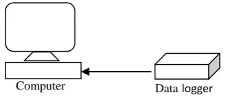
Data capturing data loggers are used only to capture the data. These devices do not have large internal memoriesand are normally connected to a PC. The captured data is sent to the PC for storage or for analysis. The data can
either be analysed offline or online. One of the disadvantages of data capturing data loggers is that the devices
cannot be used on their own as another device (e.g. a PC) is required to store the captured data.
Fig. 1: Data logger (data capture type)
The design of the data logger can be made based on the needs of specific environment or application type. Many
of the general purpose data loggers are machines with fixed parameters. However, there are some with
re-programmable capability.
In this paper a low cost development of standalone real time data logger is proposed using ARM microcontroller
and a supporting Android app to interact with the system.
II.
METHODOLOGY
The proposed data logging system consist of a microcontroller, real time clock, SD card, a Bluetooth transceiver
to communicate with Android phones/tablets and a few sensor input channels, to which multiple sensors can be
connected for measurement of parameters like temperature, humidity etc [2]. The block diagram of the system is
shown in Fig. 2.
Fig. 2: Block diagram of Data logger
As shown in the block diagram the microcontroller receives input from the sensors and converts it to digital
form. This digital data is then time stamped using RTC present inside the microcontroller. The time stamped
36 |
P a g e
III.
HARDWARE
3.1.
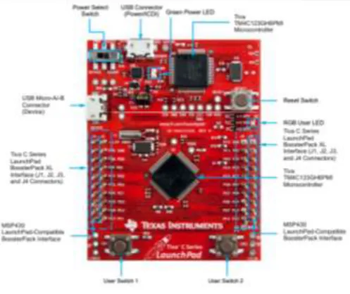
MicrocontrollerThe microcontroller used here is TM4C123GH6PM by Texas Instruments. It employs ARM Cortex M4
architecture based SoC. The various features of microcontroller which favours its use in the data logging system
are:
Two 12-bit ADC modules, each with a maximum sample rate of one
million samples/second.
Low-power battery-backed Hibernation module.
Eight Universal Asynchronous Receivers/Transmitter (UART). Synchronous Serial Interface (SSI).
Six physical General Purpose Input/output (GPIO) blocks.
Fig. 3: Microcontroller board used for system development.
3.2.
ADCThe TM4C123GH6PM ADC module features 12-bit conversion resolution and supports 12 input
channels, plus an internal temperature sensor. Each ADC module contains four programmable
sequencers allowing the sampling of multiple analog input sources without controller intervention.
Each sample sequencer provides flexible programming with fully configurable input source, trigger
events, interrupt generation, and sequencer priority. Out of the 12 available input channels 4 have been
configured to receive input from sensors.
37 |
P a g e
A 16x2 LCD is interfaced to the system to provide the user with relevant information during system operation.This LCD is also helpful during system debugging and testing.
3.4.
RTCReal-Time Clock (RTC) is built into the Hibernation module present on SoC. The RTC has a 32 bit counter with
a resolution of 1/32,768 second. Clock source to RTC is a 32.768-kHz external crystal. The RTC counter
increments every second. This counter is used to create a clock which is then used to time stamp the data.
3.5.
MemoryA SD Card is interfaced to the system using SPI. A SD card can work in two modes- SPI mode and SD mode.
Here it is used in SPI mode. In this mode no file system is implemented on the SD Card and the data written to
it is in raw format.
3.6.
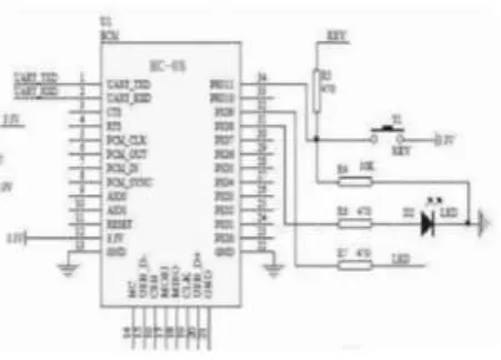
BluetoothThe Bluetooth module interfaced to the microcontroller is used for communication with the Android device. The
Bluetooth module is configured to be a slave device. Whenever data is requested from the master, it is retrieved
from the memory and transmitted as a string of ASCII characters. The microcontroller communicates with the
Bluetooth adapter through UART interface.
Fig. 4: HC-05 connection diagram
3.7.
Android deviceThe user can retrieve data logged by the system using any android device. The android device requires a
Bluetooth terminal app which is used to connect to the slave Bluetooth module present on the data logger. Once
connected to the slave, the user needs to send appropriate command to get the data. The data received can be
38 |
P a g e
IV.
SOFTWARE
The software is developed in Code Composer Studios which is an IDE provided by Texas Instruments. The
software for running each peripheral is done in separate modules. Each of these modules are tested individually
for proper functioning and then integrated into a single code file.
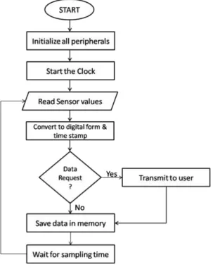
Fig. 5: Software flow diagram
After the system is powered up the software initializes all the peripherals during which Initial clock value is
written into the counter, ADC operating modes are set up, input channels are configured. The user is then asked
to determine the sampling interval (ts) which is the time interval between successive samples acquired by the
ADC. Once the initialization is over the real-time clock is started and sensor values are read. Conversion is
performed in ADC and the converted data is time stamped using time values from RTC. If the user has
requested the data then it is transmitted to through Bluetooth to the user device. This data is also saved into the
memory. After waiting for ts the process is repeated again. An android application is developed for the user
39 |
P a g e
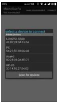
module with the Data logger is configured as a slave device and the android device acts as master device. Theapp shows the list of available Bluetooth devices out of which user needs to select the Data logger (Fig. 6).
Fig. 6: Making connection with data logger (HC-05)
V.
RESULT & CONCLUSION
The microcontroller based data logger has been developed successfully. The system is tested with varying
sampling rate and different number of sensors. As the system is having 12 bit ADC, it is possible to detect a
change of minimum 0.8056mV on the analog input channel for the sensors. Using the android app the user can
also monitor the data in real time.
The prototype hardware developed is shown in Fig. 7. As seen in Fig. 7 the LCD is displaying the current
clock/time on row 1 and the acquired sensor values on row 2.
40 |
P a g e
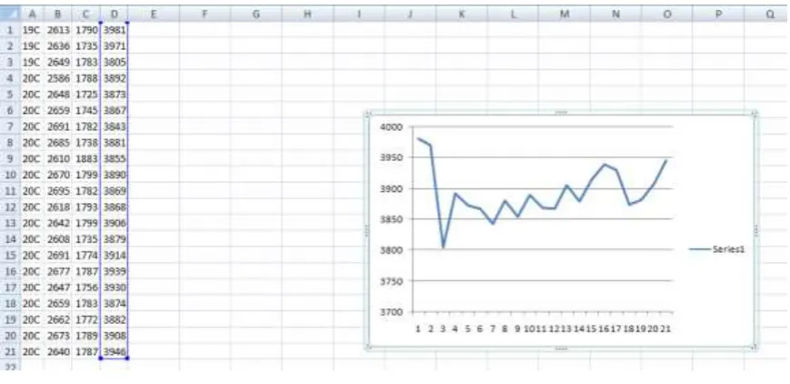
Fig. 8: Log file saved on android deviceThe log file saved in text format is shown in Fig. 8. The 4 different columns represent the data from 4 different
sensors interfaced to the system. This text file can easily be imported in Excel software and graph can be
plotted. The graph for data in column 4 corresponding to light sensor is shown in Fig. 9. Here each data value is
taken at interval of 5 seconds.
Fig. 9: Creating graph from logged data values.
VI.
FUTURE WORK
The number of input channels can be extended using multiplexer. A file system can be implemented on the SD
41 |
P a g e
developed on Android operating system; this can be done for iOS and Windows OS also. The application can beextended further to automatically plot the graph based on the acquired data from the data logger.
REFERENCES
[1]N.N. Mahzan, A.M. Omar, S.Z.Mohammad Noor, M.Z.Mohd Rodzi, “Design of Data Logger with Multiple
SD Cards,” IEEE Conference on Clean Energy and Technology (CEAT), pp. 175-180, 2013.
[2]G.S. Nhivekar, R.R.Mudholker “Data logger and remote monitoring system for multiple parameter
measurement applications,” e -Journal of Science & Technology (e-JST), pp. 55-62, June 2011.
[3]Zhan Wei Siew, Chen How Wong, Shee Eng Tan, Hou Pin Yoong, Kenneth Tze Kin Teo, “Design and
Development of a Tablet Based Real Time Wireless Data Logger,” IEEE Global High Tech Congress on