PERFORMANCE COMPARISON OF HAAR OFDM
AND DAUBECHIES OFDM IN PRESENCE OF
CARRIER FREQUENCY OFFSET (CFO) AND
DOPPLER EFFECT
Sumi K M
1, ArunShaji B K
2 1, 2Department of Electronics & Communication Engineering,
KMEA college of Engineering, Kerala, (India)
ABSTRACT
Present day wireless communication systems demand for high data rates. Orthogonal frequency division multiplexing (OFDM) has emerged as a promising technology to provide these high data rates. OFDM is a digital modulation technique which divides the available spectrum into different sub bands. As a result data can be transmitted simultaneously using multiple subcarriers. Conventional OFDM is based on Fast Fourier transform. It uses Inverse Fast Fourier transform block at transmitter side and FFT block at the receiver side. Recent studies show that discrete wavelet transform can be used in the place of FFT as it provides better Bit Error rate performance. The major degradation factors that reduce the performance of conventional OFDM are Carrier frequency offset and Doppler Effect. This paper discusses the performance of DWT based OFDM in the presence of CFO and Doppler Effect. The paper compares the BER performance DWT OFDM using two wavelets, the Haar Wavelet and Daubechies wavelet. CFO and Doppler Effect are assumed to occur individually in the system. Simulations are carried out using MATLAB.
Keywords
–
DWT OFDM, Daubechies, FFT OFDM, Haar, OFDM
I. INTRODUCTION
OFDM has been widely used in communication systems to provide high data rates. It provides both modulation
and multiplexing. It is a digital modulation scheme that provides multi carrier modulation that can transmit data
parallel on closely spaced subcarriers. The sub carriers are orthogonal to each other. Because of the
orthogonality among subcarriers and sharing of data among subcarriers, OFDM provide high bandwidth
efficiency. It allows to digitally transmitting the data in the multipath fading environment without much
distortion.
Conventional OFDM uses IFFT at the transmitter side for generating the orthogonal subcarriers. A cyclic prefix
is added to the data symbols to combat the delay spread introduced by the fading environment and CP should
have at least same size as channel delay spread. This will minimize the Intersymbol interference (ISI) among the
symbols. At the receiver side, reverse operation takes place. CP is removed and data is passed to the FFT block
to obtain the received signal in frequency domain.
Recent researches show that use of discrete wavelet transform instead of fast Fourier transform in OFDM
systems provide better performance. DWT based OFDM uses IDWT block at the transmitter side and DWT
as that of FFT OFDM .Unlike FFT OFDM wavelet system satisfies the orthogonality condition and achieves
perfect reconstruction using orthogonal filters of the quadrature mirror filter (QMF) [1]. Because of the feature
of DWT Inter Carrier lnterference can be avoided without using cyclicprefix (CP) is not needed .Different types
of wavelets can be used depending upon the purpose. Of these Haar wavelet and Daubechies wavelet are used in
the OFDM system in this paper.
As OFDM has emerged as indispensable technology, its performance has to be tested against the degrading
factors. The primary degrading factors occurring in OFDM are Carrier Frequency Offset (CFO) and Doppler
Effect[2], [3]. CFO defines the difference between the local oscillator frequencies in the transmitter and receiver
side. CFO causes the loss of orthogonality between subcarriers and lead to ICI.Doppler Effect implies the shift
occurring in the frequency of the receiver section due to channels random condition, which also leads to ICI.The
paper discusses the effect of CFO and Doppler Effect on the performance of DWT OFDM using two wavelets,
Haar and Daubechies.
The organization of paper is as follows. The succeeding section describes the system model of FFT OFDM and
DWT OFDM. Third section explains the Haar and Daubechies wavelets. Fourth section deals with the effect of
CFO and Doppler- effect over OFDM. Fifth section explains the simulation and results. Last section concludes
the paper.
II. SYSTEM MODEL OF OFDM
The general block diagram of OFDM transceiver is shown in the Fig 1.
Fig 1 Block diagram of OFDM system
The serial stream of N numbers of data are converted into parallel stream. It is then processed by suitable
modulation (QAM or QPSK or BPSK) to map the data with N subcarriers that are implemented using
IFFT/IDWT [4] .In conventional OFDM, IFFT is used for the required frequency to time domain conversion.
The output of IFFT is the sum of information signals in the discrete time domain as following:
(1)
After IFFT, cyclic prefix is added to each symbol for avoiding both Inter Symbol interference (ISI) and Inter
data is then converted to serial data and is transmitted over the channel. Using the Additive White Gaussian
Noise (AWGN) channel, the received sequence is given by:
(2)
Where H[n] is the transfer function of the channel and w (n) is the noise envelope of channel. In the recovery
process, first the cyclic prefix is removed. Then the data is given to FFT block. The data recovered from the FFT
block of receiver is expressed as:
(3)
In DWT OFDM, the IFFT block and FFT block are replaced by IDWT and DWT block respectively .Because of
the peculiarity of DWT, even without using cyclic prefix, ICI can be avoided. So the block representing addition
and deletion of cyclic prefix is not needed in DWT OFDM. Cyclic prefix is the redundant data that reduces
actual data rate. So by avoiding cyclic prefix data, both data rate and efficiency can be improved [5].
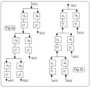
Mallet algorithm or subband coding is used to compute DWT [4].Here the data sequence is given to a series of
high pass filters and low pass filters as shown in the Fig 2. Low pass filter (G0) provides approximate
coefficientsanknown as scaling function. Likewise High Pass Filter (H0) produces detailed coefficients dn known
as wavelet function. In this algorithm, successive filtering operations are performed on the scaling function only.
As a result, one scaling function and n number of sets of wavelet functions are available at the final stage. The
filtering function also involves a down sampling procedure.
In IDWT computation, reverse operations of DWT takes place. Here the filtering in reverse order with
upsampling is involved. After constellation mapping, N parallel data streams are available at the transmitter side
.By using these data, orthonormal wavelet carriers can be generated.
Fig 2 Computation of a) DWT b) IDWT
For accomplishing this task, parallel data should be converted to serial data & should be denoted as a vector.
and low pass filtering to get approximate coefficients which denotes the actual data. To get wavelet coefficients,
the same procedures are done with zero padding and vector transposed output is high pass filtered.
Fig 3 IDWT block in transmitter
At the receiver side, DWT process is involved for data recovery. The filters G0 and H0 known as analysis filter,
used for this purpose should have matching characteristics with that of synthesis filters G1 and H1, in the IDWT
block of the transmitter. For perfect reconstruction the analysis and synthesis filters needs to satisfy the
conditions below [6]:
(4)
(5)
Equation 4 is used for making output free of aliasing and equation 5 makes output free of distortion. For keeping
the orthogonality condition, the following equation should be satisfied:
(6)
The series of filtering on the signal produces approximate coefficients and some sets of detail coefficients. After
summing up all the sets, the detail coefficients required are obtained. Finally, approximate and detail
coefficients are vector transposed (Fig 4) and output got will be in parallel format of required data. After serially
converting it, the data symbols are demapped and zeros are discarded
III. HAAR AND DAUBECHIES WAVELET
3.1Haar Wavelet
Haar Wavelet is the simplest of all wavelets [7].Mathematically, discrete Haar wavelets can be represented as
Haar transform. It defines as a sample for all supplementary wavelet transform .A discrete signal is decomposed
into two subsignals of half its length using the transform. One signal is running average, while other is a running
difference. Advantages of Haar wavelet transform include the following [8].
Conceptually simple
Fast
Memory Efficient
Exactly reversible without the edge effects
Haar transform possesses its own limitations, which make some applications difficult. While calculating each of
the averages for the next level and each set of coefficients, Haar transform does an average and difference on a
pair of values. After that algorithm is shifted over by two values and performs another average and difference on
next pair. All high frequency changes will be reflected by the high frequency coefficient spectrum. Haar
window consists of two elements only. A big change from an even to odd value cannot be reflected in the high
frequency coefficients. As a consequence, this transform cannot be used in compression and audio signal
processing. The mother wavelet function and scaling function of Haar transform is given by as:
(7)
3.2. Daubechies Wavelet
Daubechies wavelet transform is named after its inventor, the mathematician Ingrid Daubechies. Daubechies
wavelet transforms are defined in same way as Haar wavelet transform such that running averages and
differences via scalar products with scaling signals and wavelets. The only difference lies in how the scaling and
wavelet functions are defined. This paper uses the Daubechies D4 transform. It has four wavelet and scaling
coefficients.
The scaling function coefficients are given by:
Scaling function is applied to input data at each step of wavelet transform. If data has N values, scaling function
produces N/2 smoothed values.
The wavelet function coefficients are given by:
(9)
Wavelet function is applied to input data at each step. If data set has N values, wavelet function calculates N/2
differences. Daubechies wavelet has balanced frequency responses and nonlinear phase responses. As this uses
overlapping windows, high frequency coefficient spectrum reflects all high frequency changes. Thus they are
useful in compression and noise removal of audio signal processing. [8].
IV. CFO AND DOPPLER-SHIFT EFFECT ON OFDM
The received signal at the front end of the OFDM receiver in the ideal case is given in the equation 2.Ideal case
means there is no CFO and Doppler-effect. It is not practical [2],[6].
In the presence of CFO, the received sequence is given as:
+
(10)
Where is the normalized frequency offset given as . In the above equation, the first part is the
attenuation factor of the amplitude and value of phase shift that the signal experience.
Likewise, Doppler- effect also contributes to the change in carrier frequency. Consider that an OFDM system
employed mobile system has a velocity of „v‟ because of the frequency shift in carrier frequency. This is known
as Doppler-effect [3]
(11)
Where f0 represents the carrier oscillator frequency, c is the velocity of light in free space, is the angle exists
between the velocity vector and the direction of electromagnetic waves. As a result of this frequency shift, inter
(12)
The ICI caused by the carrier frequencies mismatch leads to the loss of orthogonality between the sub carriers
and as a result performance is degraded more strongly. This paper shows the BER performance of Haar wavelet
OFDM and Daubechies OFDM in the presence of CFO and Doppler- effect, considering both occurring
individually.
V. SIMULATION DETAILS
Simulation of Haar wavelet OFDM and Daubechies wavelet OFDM is done using Matlab.When simulating the
oscillator‟s mismatch at both transmitter and receiver, the mobile unit is considered to be in standstill condition.
Such that the Doppler-effect is ignored. Likewise, performing simulation for Doppler-effect, mismatch of
oscillator is not considered. In DWT OFDM the filter banks are selected in such a way that it satisfies the
condition for perfect reconstruction and renders required orthogonality. Simulation parameters are given below:
Modulation: BPSK
No of subcarriers:256
Frame length:1000
Channel: AWGN
Wavelet used : Haar wavelet & Daubechies wavelet (D4 or db2)
Fig 6 BER plot of Haar OFDM & db2 in presence of CFO
VI. CONCLUSION
OFDM can be implemented more effectively using Discrete Wavelet Transform instead of Fast Fourier
Transform. Spectral containment of channels can be improved by using this transform, as they are not using
cyclic prefix (CP).Wavelet based OFDM has orthonormal base properties and reconstruction properties. This
paper simulated two types of wavelet OFDM, one using Haar wavelet and other using Daubechies wavelet using
MATLAB software. The performance of both OFDM is compared in the presence of the degrading factors,
Carrier Frequency Offset (CFO) and Doppler-effect. Haar OFDM shows similar BER performance as that of
Daubechies 4 (db2) OFDM. In the presence of degrading factors, Haar OFDM shows slight better performance
than Daubechies OFDM.
REFERENCES
[1] V. Kumbasar, et al., “Optimization of wavelet based OFDM for multipath powerline channel by genetic
algorithm,” Wireless Communications and Mobile Computing, 2009, Vol. 9, No. 9, pp. 1243-1250.
[2] P aul H. Moose, “ A Technique for Orthogonal frequency Division Multiplexing Frequency Offset Correct
ion” IEEE Transact ions on communications, vol. 42, no. 10, October 1994 pp 2908-2914
[3] Y. Zhao and S.G. Häggman, “Sensitivity to Doppler shift and carrier frequency errors in OFDM
systems-the consequences and solutions”, IEEE Conference on Vehicular Technology,. Atlanta, GA, 1996, 1564–
1568.
[4] N.Hariprasad, & G Sundari, “Performance comparison of DWT OFDM and FFT OFDM in presence of
CFO and Doppler Effect” IEEE proceedings of 2014 International Conference on Control Instrumentation,
[5] Khaizuran Abdullah and Zahir M. Hussain, "Studies on DWT-OFDM and FFT-OFDM Systems"
Intemational Conference on Communication Computer and Power (ICCCP'09), ISSN: 1813419X.
[6] SaeedMohseni, Mohammad A. Matin “Study of the estimation techniques for the Carrier Frequency Offset
(CFO) in OFDM systems” IJCSNS International Journal of Computer Science and Network Security, Vol.12, issue No.6, June 2012, pp73-80.
[7] James S Walker. 1999. A Primer on Wavelets and Scientific Applications.