Type of the Paper (Original Paper)
1
Controlling data flows in computer networks
2
Ahmad AbdulQadir AlRababah1*
3
1Faculty of Computing and Information Technology in Rabigh, King Abdulaziz University, Rabigh 21911,
4
KSA.
5
*Correspondence: e-mail: [email protected] ; [email protected]
6
7
Abstract: In computer networks, loss of data packets is inevitable, in particular, because of the
8
buffer memory overflow of at least one of the nodes located on the path from the source to the
9
receiver, including the latter. Such losses associated with overflows are hereinafter referred to as
10
congestion of network nodes. There are many ways to prevent and eliminate overloads; these
11
methods, in the majority, are based on the management of data flows. A special place is taken by
12
the maintenance of packages, taking into account their priorities. The article considers a number of
13
original technical solutions to improve the quality of control and reduce the required amount of
14
buffer memory of network nodes. The ideas of these solutions are quite simple for their
15
implementation in the development of appropriate software and hardware for telecommunication
16
devices.
17
18
Keywords: data transmission, data stream, input output buffers, telecommunication devices, data
19
packets, blocks of memory, switching matrix, high priority packets, bitstaffing.
20
21
1. Introduction
22
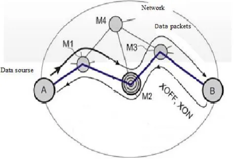
One of the known ways to control the flow of data is explained in Fig. 1, on which a fragment of the
23
computer network is shown and the trace of the data stream transmitted through it is indicated[1].
24
The packets are transferred from the node A - the data source (transmitter) to the node B - the data
25
receiver through the intermediate nodes, for example, switches and / or M1-M3 routers[2].
26
2. Materials and Methods
27
Method 1: Control the flow of data adjusting the length of pauses between packets
28
Prototype Mode 1
29
In this example, the node M2 is overloaded, its input buffer memory (in the following, for brevity,
30
the input buffer) is completely or almost completely filled with incoming data packets. New
31
packages, at least some of them, are lost due to lack of free space in the buffer[3].
32
During the data transfer, the receiver notices a persistent shortage of arriving packets (for example,
33
by tracking their sequence numbers) and sends a control packet containing the XOFF command to
34
suspend the data stream to the data source A. The address of the data source is known to the
35
receiver, since the data packets coming to it contain information about the addresses (or directly
36
addresses) of devices A and B[4]. Sending requests for retransmission of lost packets is also sent.
37
When the XOFF command is received, the data source completely stops sending packets and
38
resumes it, either after some time specified in the data exchange protocol, or after receiving the
39
renewal of transmission from the XON command receiver [1].
40
This method has several drawbacks.
41
First, data flow control is quite crude (the flow is either there or it is not). The delay in the execution
42
of commands can lead to unjustified idle of the transmitter and the periodic occurrence of new
43
overloads, in which some of the packets[5], including those belonging to other flows, will be lost[6].
44
Secondly, with prolonged overload, the receiver sends the transmitter a series of identical stopping
45
commands, which clogs the communication channel with a large number of repetitive service
46
packets[7].
47
Thirdly, the commands for suspending the transmitter are generated by the receiver only if the
48
number of packets rejected due to buffer overflows is large enough. Otherwise, if one responds to
49
insignificant packet losses, the transmitter will receive and execute suspense commands without any
50
special reason.
51
Fourth, the suspension of the transmitter increases the average and maximum packet delay on the
52
route, which can reduce the quality of service (QoS) parameters specified in the contract between the
53
user and the provider [8].
54
The idea of method 1
55
56
57
59
Figure 2. Improved way to control the flow of data: a - if there is a danger of overflow of the buffer
60
memory of the node M2; b - during normal operation
61
62
The proposed solution (Figure 2) largely eliminates these shortcomings due to a smooth and
63
"advanced event" adjustment of the data transmission rate by the source. The speed is controlled by
64
changing the length of pauses between packets: the longer the pause, the lower the data transfer rate,
65
and vice versa[9]. Note that the presence of a pause does not mean that there is no signal in the
66
communication line - the signal is present constantly, but there are no flag codes indicating the
67
beginning of the packet, or vice versa - a continuous stream of these codes is transmitted[10].
68
In the one shown in Fig. 2, and the pause situations between packets transmitted on the route A-B
69
are relatively small, or in other words, the data rate of the data placed in the packets is relatively
70
large, in the sense that the buffer memory level of the intermediate node M2 is steadily increasing,
71
which may result in buffer overflow[11]. Buffer memory for clarity is shown in the figure as a tank
72
with liquid replenished by the input stream of packets, while the output stream tends to reduce the
73
level of its filling[12].
74
In this case, the node M2 registers the operation of the second upper level sensor (the comparator of
75
read and write addresses of the buffer memory block). This means that the level of filling is close to
76
critical, therefore, it is necessary to reduce the rate of data flow to the buffer. To reduce the speed, the
77
node M2 sends to the node A a service packet, a command to increase the pauses between
78
packets[13].
79
In response to this command, node A increases the duration of pauses between packets (Figure 2, b).
80
network or in the explicit form indicated in the service package. After increasing the pauses, the
82
buffer memory level of the M2 node starts to decrease, if there is no other reason for its increase[12].
83
Upon reaching the central or lower mark, the node M2 sends to the node A the command to reduce
84
the duration of the pauses, the level of the buffer filling again begins to increase, etc.
85
Thus, in an ideal case, the buffer memory of node M2 does not overflow and does not emptied, the
86
speed of data output from the buffer memory remains constant, the rate of data arrival adapts to it,
87
making slow fluctuations inherent in conventional automatic control systems[14].
88
If there are several data sources, then to prevent overload the work of the most active one, but not
89
the most priority, is slowed down; if the sources are equally active, then the impact on those with
90
low priorities is primarily affected[8].
91
In the development of the described method, it is proposed to take into account, not only the level of
92
the buffer completion, but also the dynamics of its change when forming commands for decreasing
93
or increasing the intensity of the flow[15]. This allows eliminating unnecessary flow control
94
commands when the buffer fill level is high, but the history of the process is such that there is a
95
steady tendency to stop its growth and the subsequent decrease (and vice versa). Essentially, along
96
with absolute reference, the rate of change in the rate (acceleration) of the motion of the level of
97
buffer memory filling is considered[16].
98
99
Method 2: Managing the flow of data by notifying the packet source of causes of overload
100
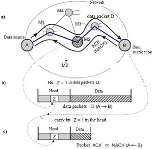
Prototypes of method 2
101
Let's continue our consideration of the known methods of data flow control (Fig. 3) using the same
102
network model as before (Figure 1, 2). The data source A transmits a series of data packets to the
103
receiver B. In response to each packet or to a group of packets, the receiver B sends the ACK or
104
NACK response packets to the source A. The ACK response acknowledges the successful reception;
105
the NACK response is a request to retransmit a single packet or group of packets[14].
106
The first prototype of method 2. In principle, even such a simple feedback (using ACK or NACK
107
response packets) allows detecting and eliminating network congestion on the A TO B path[17].
108
Indeed, if the data source is increasing the packet rate or at some fixed rate starts to receive an
109
excessive number of retransmission requests, then, most likely, at least one of the nodes of the route
110
112
Figure 3. Informing the data source A about the upcoming or available overload of the input buffer
113
of the M2 node of the network: a - packet propagation paths b, c - packet structure D and ACK
114
(NACK)
115
116
In this case, the data source drastically reduces the packet transmission rate or (and) increases their
117
length to reduce the share of the overhead bits that make up the headers in the data stream[19]. In
118
the future, the data source gradually either by random trial and error increases the data transmission
119
speed, moving to the permissible upper limit, taking into account some permitted speed increase
120
margin. Such a method is called a "slow start".
121
Of course, packet loss is possible, not related to the overload of network nodes, for example, due to
122
uncorrectable errors caused by interference in the communication line, but in this case we are not
123
interested in such losses[20].
124
The considered method of data flow control does not prevent the forthcoming loss of packets, but
125
allows reacting only to the accomplished fact of overloading of the intermediate node of the network
126
or the data receiver[21]. This is its main defect.
127
The second prototype of method 2. The idea is to warn in time the data source A about the threat of
128
overloading one or several nodes along the route A In the propagation of data packets D. This
129
warning is the bit Z included in the header of the ACK or NACK response packet[22] (Figure 3, c).
130
In the example shown in Fig. 3, the processor of node M2 anticipates overload, observing the
131
steadily increasing level of buffer filling, as it was shown on its model, shown in the right part of Fig.
132
In packages passing through the node M2, more precisely, in the header of each of them, there is
134
information sufficient for its routing, for example, in the form of IP addresses of the source and the
135
data receiver[24]. Viewing this information allows the M2 node to identify the "culprit" of the
136
expected overload, from which the most intensive flow of packets originates. There can be several
137
such.
138
Suppose that the main "culprit" of the impending congestion is the data source A. This source, like
139
all others, transmitting data packets D, sets the Z bits to zero. With normal data transmission on the
140
route A TO B, these bits remain in the zero state[25].
141
If the conditions for the upcoming overload are detected and knowing that the largest number of
142
packets per unit of time originate from the source A, the node M2, when transmitted along the route
143
A TO B, marks all packets or a part of them with their Z = 1 bits that inserts in the headers, as shown
144
in Fig. 3, b. The data receiver B returns the received Z = 1 bits to source A, including them in the
145
headers of the response packets ACK and NACK (Figure 3, c).
146
Finally, data source A receives bits Z = 1 and sharply reduces the data transfer rate to node M2[26].
147
Further, the data source A gradually restores the original data flow parameters or even exceeds the
148
previously reached data transmission rate until a new series of bits Z = 1, etc., is detected (here, too,
149
the "slow start" mentioned earlier is applied). Having determined the allowable upper speed limit,
150
the data source takes a small step down to create some margin, guaranteeing the route from
151
overload[27].
152
This way of preventing or eliminating overloads is satisfactory, but not optimal. Its disadvantage is
153
that, without knowing the reason for the overload of node M2, the source of data A is unable to
154
adequately respond to it. So, the "natural reaction"
155
- a sudden and sharp decrease in the data transfer rate - is unacceptable for many applications. But if,
156
for example, the data source A knew that the reason for the upcoming overload was that the
157
processor of the M2 node could not cope with header stream processing, then it could, without
158
reducing the transfer rate of payload data, increase the packet length to reduce the intensity of this
159
flow[28].
160
The problem solved by the method 2 discussed below is thus not only to prevent the source of data
161
on the impending overload, but also to inform him of its cause. Then the source could choose the
162
most appropriate "line of behavior" in this situation[29].
163
The idea of method 2
164
The problem is solved by extending the single-digit sign Z to several bits. Let us explain what has
165
been said by example, accepting some assumptions.
166
Suppose that route A-B (Figure 3) is a virtual telephone link between devices A and B, for example,
167
between computers or IP telephones. The technology of VoIP (Voice over IP) is used. Devices A and
168
B contain codecs such as AMR (adaptive multi rate)[30]. The codec generates compressed speech
169
fragments every 20 msec and encodes data from one of eight speeds in the range from 4.75 to 12.2
170
kbps. Further, as before, one-way data transfer from device A to device B is considered[31].
171
After the connection A-B is established, the data source generates packets, each of which contains a
172
header and a data field. The data field of the packet is filled with fragments of speech from the codec
173
output, and then the packet is sent along the communication line to node M2[32]. The codec, if the
174
bandwidth of the A-B channel allows, is initially set to the maximum coding rate to ensure the
175
highest speech intelligibility recovered from the data input to receiver B. The Z bits of the sent
176
In the event of detection of the danger of overload by some node located along the A TO B route, this
178
node (in our example, the M2 node) inserts some indication Z in the headers of packets originating
179
from the most active source (A), as described earlier, taking into account that this feature contains
180
not one, but at least two bits. This attribute is returned to the source; as a result, the processor of
181
node A receives information about the reason for the upcoming overload.
182
The node M2 may experience overloading for at least one of the following reasons.
183
1. Narrowing the bandwidth (bandwidth) of the channel A TO B due to the appearance of a
184
"bottleneck." This can happen, for example, because a part of the dedicated link A TO B of the
185
linkage between the nodes M2 and M3 (Figure 3) has decreased. This decrease may be due to various
186
reasons. Let's name two of them.
187
- The previously unobtrusive competing data flow along the route M4 M2 M3, which uses the
188
same channel M2 to M3, as the route A TO B, has increased to a significant level earlier. As a result,
189
the M2 node redistributed the strip of this channel to the detriment of the route A TO B .
190
- The M2 node has changed the type of signal modulation in the M2 to M3 channel, reducing the
191
transmission rate due to the deterioration of the signal-to-noise ratio in this channel.
192
2. The M2 node processor for some reason or other has stopped coping with the volume of work
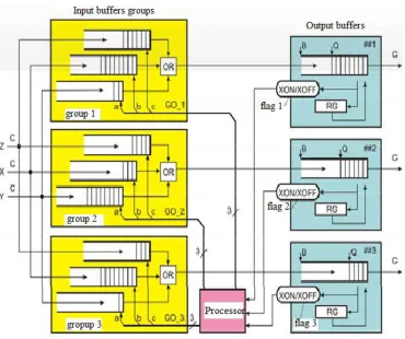
193
on analyzing packet headers following the route A TO B.
194
The first and second reasons above for the approaching overload are displayed respectively by the
195
codes Z = 012 and Z = 102, the absence of an overload hazard corresponds to the code Z = 002, both
196
causes simultaneously generate the code Z = 112. The code Z = 112 can Form one node if it
197
simultaneously observes both reasons for the upcoming overload, or by two or more nodes located
198
along the A to V.
199
So, the node M2 can insert the Z = 102 codes into the headers of the A B packets that pass along the
200
route, because the processor of this node cannot cope with the volume of work on the analysis of
201
headers. These packets are transmitted to the M3 node, which is supposed to reveal a decrease in the
202
M3 to B channel bandwidth allocated to the A to B route. In this case, the M3 node replaces the Z =
203
102 codes in the packets passing through it with Z = 112. These codes, as described, reach the
204
receiver B and return to the data source A as part of the headers of the response packets (Figure 3, c).
205
The optimal response of the data source to the identified causes (1 or 2) of overloading may be this.
206
The narrowing of the channel bandwidth A to B (reason 1) should cause a corresponding decrease in
207
the total data rate (both useful and service) of the source A. To estimate the rate reduction, it would
208
be desirable to use a multi-bit code Z in which this degree is reflected. However, in this case there is
209
no such possibility, therefore the processor of the data source A switches its codec to the mode of the
210
lowest encoding speed (out of eight possible - from 4.75 to 12.2 kbps). If the packet length is
211
unchanged, and the lowest
212
The frequency of their succession decreases due to the increase in pauses between them. At the same
213
time, the delay in the formation of the packet increases due to the increase in the time it is filled with
214
compressed fragments of speech. Thus, the data transfer rate (both useful and service data) is
215
reduced by source A, and if the narrowing of the band is not too large, then there is no danger of
216
overloads.
217
In the future, to restore the high quality of voice transmission, the coding rate and, correspondingly,
218
the packet repetition rate gradually increase to the experimentally detected limit, in which there is
219
Alternative response of the data source to the narrowing of the channel band A to B also provides for
221
using the lowest encoding rate. When this keeps the packet repetition rate, and their length
222
decreases. The rate of transfer of useful data decreases, the service data flow remains unchanged.
223
Finally, the strongest reaction is possible, at which the coding rate is set to the minimum, and the
224
length of the packets increases to such an extent that their average delay approaches the permissible
225
limit (not more than 100 ms [3]), after which, during a telephone conversation, begins eavesdropped.
226
Such a reaction is the maximum that can be done in this situation.
227
After exiting the crisis, the coding rate gradually increases, and the length of the packets decreases
228
with this in time (to reduce the delay of their transmission along the route A to B). This process of
229
two-dimensional optimization of flow parameters is completed when the boundary is reached, after
230
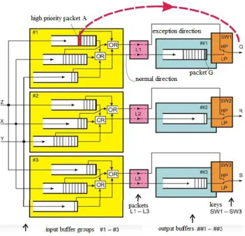
which the risk of overloading again arises.
231
Overloading the processor of one or more nodes on the A to B route (reason 2) is eliminated by
232
reducing the intensity of the header stream that it (they) has to process. For this, while maintaining a
233
high coding rate, the data source increases the length of the transmitted packets to such an extent
234
that their average propagation delay along the A to B path does not exceed the previously
235
mentioned allowable limit (100 ms).
236
Thus, the correct response to the overload warning in many situations allows to eliminate the danger
237
of overflow of input buffers and, what is essential, to maintain high quality of voice transmission.
238
239
Method 3: Control of the flow of data with compensation of the inertia of the feedback loop
240
Prototype of method 3
241
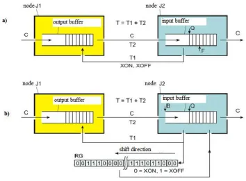
One of the simplest ways to control the flow of data transmitted between the nodes of the network J1
242
and J2 (Figure 4, a) is as follows.
243
In steady state, data packets are accumulated in the output buffer of node J1 for transmission along a
244
certain route, possibly through other network nodes (not shown in the figure) to the input buffer of
245
node J2. Both buffers are executed in the form of blocks of memory of type FIFO.
246
The flow of data packets passing through the system from the left to the right has the character of
247
"machine-gun queuing", since the series of packets are transmitted by the J1 node via the
248
communication line only with the permission of the receiver, node J2, which "causes fire to the
249
extent possible". The instantaneous packet transfer rate inside the series is C; the average speed is
250
less than the instantaneous one and depends on the average ratio of the pauses between packets to
251
the length of the series. The unevenness of the arrival of packets in the buffers of the nodes J1 and J2
252
causes fluctuations in the levels of their filling. The challenge is to protect these buffers from
253
overflow or emptying.
254
Further, this task is solved only with respect to the input buffer of the node J2, however, the output
255
buffer of the node J1 can be protected in a similar way by introducing feedback from the source of
256
the packets sent to it (in the figure this source and its feedback are not shown). Such a successive
257
chain with feedbacks between neighboring elements can be arbitrarily long. Each transmitting port
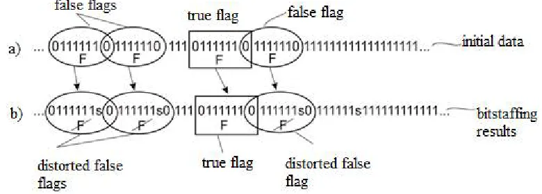
258
thus issues a stream of packets to the communication line only if there is a transmission permission
259
previously received from the destination of the XON command.
260
The input buffer of node J2 contains a pointer to the threshold level F of its filling. In this example,
261
threshold level filling in the F upward side (Q < F), the node J2 transfers to J1 the packet with the
263
XOFF command of the transmission suspension. Similarly, at the moment overcoming the current
264
level Q filling the threshold level F downwards (Q>= F), the J2 node sends a packet to the J1 node
265
with the XON resumption command.
266
267
Figure 4. Flow control scheme: a - traditional; b - the proposed
268
The problem is that flow control can be very inertial.The response time of the system to the XON and
269
XOFF commands is determined by the delay T = T1 + T2, where
270
T1 - the time from the instant the command is generated by the node J2 until the previously stopped
271
process of sending packets by the node J1 resumes or the previously activated process of issuing
272
packets by the node J1 is suspended;
273
T2 - the time of packet transmission from the output buffer of node J1 to the input buffer of node J2.
274
Thus, if the increasing filling level of the input buffer of the node J2 has overcome the threshold
275
value F, then the generated XOFF command will stop the flow of packets at the input of the node J2
276
only through the time T. During this time, the input buffer of the node J2 continues "by inertia "To
277
replenish.
278
Similarly, the first packet after issuing the XON command to resume the previously-stopped stream
279
will arrive at the input buffer no earlier than the time T. During this time, the level of filling the input
280
buffer of the node J2 "by inertia" is reduced due to the outflow of data from it.
281
If the capacity of the input buffer of node J2 is small, then the inertia of the control can lead to
282
overflow or emptying. In the worst case, after the moment of exceeding the threshold level F (Q < F,
283
the command XOFF is issued) and at the time no outflow of data from the input buffer of the node J2
284
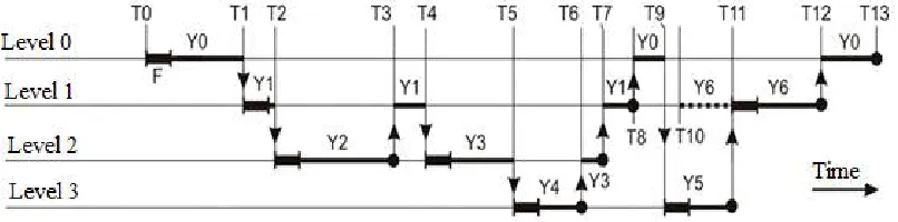
during the time T in this buffer "by inertia" will come with C*T packets.
285
Similarly, if there was no inflow of data, after the moment of crossing the threshold level F in the
286
direction of decrease (Q = >F, the command XON is issued) and with continuous data flow from the
287
Thus, to protect against overflow and emptying, the input buffer of node J2 should be designed to
289
store at least 2С*Т packets; the threshold F must correspond to its middle.
290
The resulting estimate of the minimum buffer size is disappointing. Some switches contain several
291
hundred buffers, so the actual task of reducing their volume is actual. In high-speed networks, the T
292
value reaches tens and hundreds of microseconds. The value of C is of the order of 10 Gbit / s. As a
293
result, the buffer size 2С Т = 2 1010 10–4 is several megabits. The goal of the next
294
solution is to reduce the buffer size by half thanks to smoother flow control.
295
296
The idea of method 3
297
Smoothness of control is achieved by fragmentation of series of packets and more intelligent
298
algorithm of forming commands XON and XOFF to resume and stop transmission of the stream.
299
The circuit shown in Fig. 4, b, [4] contains the same components and has the same parameters (T, C,
300
Q), which have just been discussed. The volume of the input buffer of the node J2 is denoted by B.
301
The new element of this node - the history memory of the control - is shown for clarity in the form of
302
a shift register RG, although it can be executed programmatically using a set of memory cells.
303
For definiteness, suppose that the flow of ATM cells is transmitted via the communication channel
304
[5]. (The term "cell" is equivalent to the term "packet".) This stream is continuous - after the last bit of
305
the previous cell, the first bit of the next is transmitted. The length of the cell is 53 bytes. The cells
306
follow the line of communication with a period of 40 ns. This does not mean that the proposed idea
307
is applicable only to ATM technology - it is easy in the following description to operate with strictly
308
prescribed quanta of time with duration of 40 ns.
309
Suspension of the flow in this case is conditional (a continuous stream of cells follows the connection
310
line always) and means that the output of the nodes J1 accumulated in the output buffer really stops,
311
but instead of them, bypassing this buffer, empty cells of the same length are output into the
312
communication line, as well as cells with data. Empty cells can be inserted once or form more or less
313
lengthy sequences. Blank cells are rejected by the J2 node and do not enter its input buffer.
314
Suppose that the time T = T1 + T2 = 2 μs, that is, corresponds to the passage of 50 cells. The rate of
315
issuing commands XON or XOFF is equal to the rate of arrival of cells (empty and non-empty) at the
316
input of node J2, that is, commands are issued every 40 ns. The commands issued by the node J2 in
317
response to each incoming cell on the communication line affect the input stream after a time of 50
318
cells - this is the inertia of the control loop.
319
Simultaneously with issuing the XON or XOFF command from node J2 to node J1, it is stored as the
320
corresponding bit (0 or 1) in the right-hand bit of the shift register RG, the remaining bits are shifted
321
one position to the left, the leftmost bit is pushed out of the register. Thus, in the RG register, the
322
history of issuing control commands for the next 50 cycles (the periods of succession of the cells) is
323
displayed.
324
Each XON or XOFF command when entering J1 is responsible for making a decision to issue one
325
(regular) cell either from the output buffer of this node (when receiving the XON command) or from
326
a source of empty cells to bypass the output buffer (upon receipt command XOFF).
327
The code in the RG register is analyzed by the J2 node. Counting the number of zeroes contained in
328
it, the node predicts the number of cells with data that will go to its input buffer within the next 50
329
cycles. The single bits in this register correspond to the number of empty cells that will arrive at the
330
The formation of XON or XOFF commands is as follows. Let NON be the number of zero bits in the
332
RG register, B the size of the input buffer of the node J2, Q the current size of the queue. Then:
333
if Q + NON В, then the XOFF command is generated; otherwise, the XON command.
334
Indeed, in the worst case, when there is no outflow of data from the input buffer of the node J2, the
335
expected level of its filling is equal to the current level of Q, increased by the number of NON cells
336
that are actually already in transit and will surely be received in the next 50 cycles. The expected
337
level of buffer filling Q + NON should not exceed its size B. If this condition is met, then the thread
338
should not be suspended, so the XON command is generated. In the opposite situation, when the
339
predicted level of buffer filling exceeds the volume of the buffer, stop the flow for at least one clock
340
cycle, that is, generate the XOFF command.
341
The commands, of course, will have an effect only after 50 clock cycles, but due to the "smallness" of
342
their action and the integration of many commands in time, the total effect is expressed in that the
343
fluctuations in the buffer fill level become smaller, and the necessary buffer memory capacity is
344
reduced by two times.
345
So, in the steady state, the average level of buffer memory of the J2 node is close to V / 2, in the 50-bit
346
RG register the average number of zeros and ones is approximately the same. Suppose that B = 50,
347
the average level is 25. Then the stocks in relation to overflow and emptying the buffer will be 25
348
cells in each direction. This is consistent with the fact that the average number of arriving cells
349
expected in the nearest time interval T is 50/2 = 25.
350
In the prototype (Figure 4, a), in the worst case (in the absence of data outflow from the buffer), at the
351
time T, 50 cells arrive at the input of the buffer of node J2. Similarly, in the opposite situation, in the
352
absence of data flow to the buffer, the level of its filling during the time T will decrease by 50 cells.
353
Therefore, to create the necessary reserves of 50 cells in each direction, a buffer with a volume of 100
354
cells is needed, which is twice as large as when using method 3 (Figure 4, b).
355
356
Expanding the scope of the method 3
357
Previously, the idea of reducing the amount of buffer memory of the receiver when building a data
358
transfer system between nodes of a computer network was considered. However, this idea can find
359
wider application.
360
As an example, consider the circuit of the commutator (Fig. 5). As usual, to simplify the description,
361
we assume that the data streams propagate only in one direction - from left to right. In fact, to
362
construct a switch operating with flows of both directions, it is necessary to apply the same circuit
363
deployed in the opposite direction, superimpose the resulting circuit to the original one, and
364
combine the corresponding external inputs with the outputs.
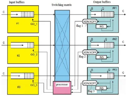
365
The switch contains three input buffers # 1 - # 3, a switching matrix, a processor and three output
366
buffers ## 1 - ## 3. Comparing Fig. 5 with Fig. 4b, one can note the similarity between the block
367
structures used in both schemes. Some designations also coincide, therefore further are not
368
explained. The signals GO_1 - GO_3 from the rightmost cell of the corresponding input buffer of
369
type FIFO are given a data packet, with the queue moving one position to the right.
370
Data packets from independent sources, for example, from computer network nodes, enter the input
371
buffers of the switch. As a result, buffers create queues of packets waiting to be sent to the output
372
buffers. The directions of packet transmission are detected by the processor based on the analysis of
373
375
Figure 5. Structure of the switch, the first option
376
377
The packets are transferred from the input buffers to the output through the switching matrix under
378
the control of the processor. Packets of some types are sent simultaneously to all output buffers or to
379
some subset of them. The switching matrix allows simultaneous transmission of packets in different
380
independent directions. For example, simultaneously with the transfer of a packet from the buffer #
381
1 to the buffer ## 3, transmissions along the directions # 2 ## 1 and # 3 ## 2 can be carried out.
382
In the output buffers, queues of packets awaiting delivery to the corresponding communication lines
383
are also created. In each of these buffers, the previously discussed method of preventing overflows
384
and devastations of the queue is applied (Fig. 4, b). However, in this case (Figure 5), the output
385
buffer "does not know" from which directions and in what order the data is expected to arrive, ie, it
386
does not have information about which input buffers and which sequence should be sent the results
387
of the queue state forecasting - the XON or XOFF commands.
388
Therefore, the output buffers form the XON / XOFF flag bits (flag 1-flag 3), irrespective of which
389
input buffer will be affected. The flags are polled by the processor and used by the processor to
390
control the transmission of data through the switching matrix.
391
Looking through the outputs of buffers # 1 - # 3, the processor monitors a lot of packets, ready to be
392
sent to the buffers ## 1 - ## 3. The decision to send each of these packets is accepted by the processor
393
only if the flag of the corresponding output buffer is set to the enabling state - XON. Then the
394
processor creates the required path through the switching matrix and initiates the issuance of the
395
packet by the command (signal) GO_i (i = 1, 2, 3).
396
The structure of the switch (see Figure 5) has a drawback that is not related to the application of the
397
If the packet type provides its transfer to a group of several output buffers, the processor does not
399
wait for the entire group to receive data at the same time to speed up the process. It transmits copies
400
of this package sequentially, as the output buffers that make up the group appear. In this case, until
401
the complete distribution of the packet across the whole group of output buffers, this packet is not
402
removed from the input buffer and therefore prevents the progress of the queue in it.
403
A similar situation (blocking of the input queue) can be observed when sending a normal packet
404
addressed to only one output buffer. If the output buffer is not ready for data reception for a
405
relatively long time, then the packet remains at the output of the input buffer, and the queue in it
406
does not advance, but only grows with the arrival of new packets. This queue may contain packages
407
that could be serviced, since the corresponding output buffers are ready to receive data, but they are
408
all prevented by the priority packet waiting for maintenance and blocking access to the rest of the
409
packets to the switching matrix.
410
411
Figure 6. Switch structure, second option
412
413
Blocking of input queues is eliminated in the scheme shown in Fig. 6. In comparison with the
414
previously considered circuit (Figure 5), the input buffers are replaced by buffer groups, the
415
switching matrix is excluded. Each group of input buffers accumulates more than one queue for the
416
number of input channels of the switch. Each group of input buffers transfers data to the
417
corresponding output buffer.
418
Packets coming from the input channels Z, X and Y are sorted. Packets of channel Z, which should
419
get into the output buffer ## 1, are written to the upper buffer of group # 1. Packets of the Z channel,
420
intended for sending to the line through the buffer ## 2, are written to the upper buffer of group # 2.
421
Packets of channel Z, which should be sent to the output buffer ## 3, are written to the upper buffer
422
The processor analyzes the flags 1 to 3 and, in the presence of the readiness of one or more output
424
buffers, receives one or more GO_i signals (i = 1, 2, 3) to receive data. Each of these commands is
425
addressed to one group of input buffers. Since in this example the group contains three buffers, the
426
command contains three bits that indicate from which queue the next data packet should be issued
427
via the OR gate. Commands (a, b, c) = (0, 0, 1), (a, b, c) = (0, 1, 0) and (a, b, c) = (1, 0, 0) correspond to
428
the issuance The data packet from the upper, middle and lower case of the selected group. The
429
queue number can be transmitted from the processor with binary code with its decoding in groups
430
of input buffers, but this possibility is not considered to simplify the figure.
431
If one of the output buffers is not ready to receive data for a relatively long time, this does not affect
432
the transmission of packet flows through other output buffers. For example, the output buffer ## 1
433
may not be ready to receive data (flag 1 in the XOFF state), then the GO_1 signal remains zero for
434
this time (0, 0, 0), preventing the issuance of packets from group 1. Other groups remain in normal
435
operating mode, i.e., as far as possible under the control of the processor, data is transferred to the
436
corresponding output buffers.
437
3. Discussion
438
Accelerated transmission of high priority packets through the switch. The switch shown in Fig. 7,
439
is an improved version of the previously considered structure (Fig. 6). Comparing Fig. 6 and Fig. 7,
440
one can note that some of the previously considered elements in Fig. 7 are not shown, although they
441
may be present in the circuit. At the same time, new elements have been introduced, the functions of
442
which do not violate the work of the previously considered schemes. The purpose of introducing
443
new elements is to accelerate the transfer of high-priority packets through the switch.
444
Just like in the previous scheme, the switch contains three groups # 1 - # 3 input buffers of type FIFO.
445
The outputs of these buffers in each group are connected through the first logical OR and the L1-L3
446
packet converters with the inputs of the output buffers ## 1 - ## 3. In each group of input buffers, the
447
second logical OR is added, through which bypass paths (without queue) pass high-priority
448
covenants, if they enter buffers.
449
Switches SW1 to SW3 translate packets either from the corresponding queues located in the buffers
450
## 1 - ## 3, or from the workarounds. In the first case, the key is set to LP (low priority), in the second
451
- to HP (high priority). Coordination of actions of all components of the multiplexer is performed by
452
one or several processors (in Figure 7 processors are not shown).
453
In general, the proposed idea is as follows: As in the previous scheme (Figure 6), the packets
454
arriving from the input channels Z, X and Y are sorted. Packets of channel Z, which are addressed to
455
buffer ## 1, are written to the upper buffer of group # 1. Packets of channel Z, addressed to buffer ##
456
2, are written to the upper buffer of group # 2. Finally, the Z channel packets addressed to buffer ## 3
457
are written to the upper buffer of group # 3. Packages from the input channels X and Y are sorted
458
similarly.
459
Then the packets are moved along the corresponding input queues, through the first logical OR
460
elements and the lower channels of the converters L1 to L3 are transmitted to the output buffers ## 1
461
- ## 3 and in the order of their arrival are output from them to the output lines Q, R and S via the
462
keys SW1 to SW3, which are in the LP state.
463
This "natural" sequence of events is violated with the arrival of a high-priority packet, for example,
464
in the upper buffer of group # 1. All new arrivals in the buffers, packets are checked for priority.
465
Suppose first that the number of priority levels is two, and the high-priority packet came at a time
466
when all other packets on the switch have low priorities. The priority level of the package is
467
469
Figure 7. Switch structure with accelerated maintenance of high-priority packets
470
471
In the known switch structures, a simple and understandable reaction to the entry of a high-priority
472
packet was adopted:
473
• If the desired output link is not used, then the high priority packet immediately, without delay,
474
begins to be issued to it;
475
• If the communication line is busy transmitting a low-priority packet, the delivery of a high-priority
476
packet is delayed until it is released.
477
The latter circumstance leads to delays in switching high-priority packets, which for some
478
applications is highly undesirable or even unacceptable. In the worst case, a high-priority packet
479
may be a little late at the time of issuing a low priority, which may have a significant length, for
480
example, 1500 bytes.
481
The proposed solution allows interrupting transmission of the low-priority packet practically at any
482
stage, then to transmit a high-priority packet and only then resume the interrupted transfer. Nested
483
interrupts are possible if the number of priority levels exceeds two. Let us consider this solution in
484
more detail.
485
Suppose that in each transmitted packet (Figure 8), in addition to the address and other information,
486
its priority P and length N are indicated. The codes P and N can be located, for example, in two
487
adjacent bytes, with three bits defining one of the eight priority- and the remaining 13 bits are the
488
equal to (U + 213 - 1) bytes. All transmitted packets pass through converters L1-L3 (Figure 7), where
490
each of them is bit-oriented and is preceded by a unique flag.
491
492
Figure 8. Conversion of packets by blocks L1-L3 (Figure 7)
493
494
Recall that bit staffing allows you to exclude from the data stream a random copy of the unique code
495
selected as the frame start flag F. In this example, F = 01111110.
496
In Fig. 9, and the "true" flag F of the beginning of the frame (circled in a rectangular frame) is inserted
497
into some sequence of bits. The problem is that, most likely, this sequence also contains codes
498
01111110, which can be considered as false flags. In order to prevent the transmission of false flags to
499
the far side of the communication channel, they are intentionally reversibly distorted, for example,
500
according to the algorithm proposed in [7].
501
502
Figure 9. Improved bitstaffing: a - the initial sequence of bits with the "true" flag of the beginning of
503
the frame introduced into it; b - the same sequence after excluding false flags from it
504
505
This algorithm is as follows. The original sequence of bits with the "true" flag inserted into it is
506
viewed through a sliding seven-bit window in order to detect in it the code 0111111, almost
507
coincident with the flag. If such a code is detected and is not a component of the "true" flag, then it is
508
supplemented by a single bit of s, regardless of the value of the subsequent bit (Figure 9, b). Such a
509
procedure is called bitstaffing.
510
Bitstaffing does not apply to "true" flags, so they become unique, since all false flags are deliberately
511
On the far side of the communication channel, the reverse operation is performed - bits s (following
513
the sequences 0111111, which are not constituent parts of the "true" flags) are destroyed.
514
In contrast to the classical bitstaffing used in the HDLC protocol, the variant proposed in [7] allows
515
us to reduce the redundancy introduced into the initial bitstream by half. Indeed, for a single
516
random sample, the probability of detecting a 7-bit code (0111111) in a random data stream is 1/27 =
517
1/128. In the classical version of bitstaffing, the probability of detecting a 6-bit code (011111) in a
518
random data stream is 1/26 = 1/64. In other words, the insertion of redundant bits in the classical
519
version of bitstaffing is carried out twice as often as in the version proposed in [7].
520
Suppose that in the initial state, a low-priority packet is sent to the line from the output buffer ## 1 of
521
the switch (Figure 7). The SW1 switch is set to LP. As shown in Fig. 10, a, at some time T0, a high
522
priority packet arrives from the upper channel of the packet transformer L1, bypassing the output
523
queue. The transmission of the low priority packet terminates in the nearest bit interval, the SW1
524
switch goes to the HP state and the first flag bit of the high priority packet is placed in place of the
525
not transmitted bit. Then all the bits of this packet are transmitted (Fig. 10, b).
526
527
Figure 10. Interruption of low-priority data stream high priority: a - low-priority data packet; b -
528
high-priority data packet; c is the total data flow in the line
529
At the time T1, the last bit of the high priority packet is transmitted. The key SW1 returns to the LP
530
position. Following the last bit of the high-priority packet, all the bits of the previously suspended
531
low-priority packet are transmitted. The total data flow (Fig. 10, c) can be divided on the far side of
532
the communication channel into two components corresponding to Fig. 10, a and b, due to the
533
uniqueness of the flags F and the presence of the P and N fields in the packet headers.
534
To simplify the analysis of code situations by the receiver, one can accept the condition that the
535
low-priority packet flag is protected from interrupts, i.e., not crashed when switching to a
536
high-priority packet transmission. In other words, if a high-priority packet has entered the SW1 key
537
during the low priority packet transmission, it is delayed and its transmission begins only after the
538
low-priority packet flag is fully transmitted. In the worst case, the delay is eight bit intervals.
539
With a greater number of priority levels, the described process of switching data flows acquires the
540
nature of nested interrupts widely used in microprocessor technology. As shown in Fig. 11, the
541
transmission of packets can repeatedly go from one priority level to another and back.
542
In the period T0 - T1, the packet Y0 of the zero (lowest) priority level is transmitted to the line. At
543
time T1, this transmission is interrupted due to the arrival of the Y1 packet of the first (higher)
544
priority level. The transmission of the packet Y1, in turn, is interrupted at the time T2, after which
545
the Y2 packet of the second priority level is fully transmitted. The end of the transmission of this
546
548
Figure 11. Transmission of data packets Y0 to Y6 using a four-level priority system
549
550
At time T3, the switch returns to the transmission of the packet Y1, but at the time T4 the
551
transmission is again interrupted by the higher priority packet Y3, which in turn is interrupted by
552
the Y4 packet at the time T5. This packet has the highest priority; therefore its transfer cannot be
553
interrupted under any circumstances.
554
Further, at the moments T6 to T8, in the order of decreasing priorities, the transmissions of the
555
packets Y4, Y3, Y1 are completed, and the transmission of the packet Y0 resumes. At time T9, this
556
transmission is again interrupted by a Y5 packet having the highest priority. At time T10, the Y6
557
packet is ready for dispatch, but it is performed only starting from the moment T11, when the
558
transmission of the Y5 packet is complete. At the moments T12 and T13, the transmission of the
559
packets Y6 and Y0 is completed.
560
561
5. Conclusions
562
High-priority packets are "wedged" into low-priority packets, without waiting for the end of
563
their transmission. This allows reducing delays in high-priority packets even with low-priority
564
packets of long length. The increase in the intelligence of telecommunication devices became
565
possible to apply more sophisticated algorithms and original flow control schemes in comparison
566
with the known ones. This allows solving the following tasks:
567
• reduce the likelihood of overflow and emptying of buffer blocks located along the
568
distribution routes of packets and, ultimately, improve the quality of computer networks;
569
• reduce the required amount of buffer memory;
570
• improve the efficiency of servicing high-priority packets.
571
The article considers a number of original solutions to these problems at a level sufficient for the
572
development of new generations of telecommunication devices and systems.
573
574
References
575
576
1. Fujioka, Y., M. Kameyama, and M. Lukac. A dynamically reconfigurable VLSI processor with hierarchical
577
structure based on a micropacket transfer scheme. in Information and Digital Technologies (IDT), 2017
578
International Conference on. 2017. IEEE.
579
2. Drumm, D.E., Computer input device using an orientation sensor. 1991, Google Patents.
580
3. Sansyzbaevich, I.S., et al. Development of algorithm flow graph, mealy automaton graph and
581
mathematical models of microprogram control mealy automaton for microprocessor control device. in
582
Control and Communications (SIBCON), 2017 International Siberian Conference on. 2017. IEEE.
583
4. Sidler, D., et al. Accelerating pattern matching queries in hybrid CPU-FPGA architectures. in Proceedings
584
5. Wu, E.-I., Control device for vehicle hiring and control system using same. 2017, Google Patents.
586
6. Aslam, M.H., et al., Exploring the effect of LUT size on the area and power consumption of a novel
587
memristor-transistor hybrid FPGA architecture. Arabian Journal for Science and Engineering, 2016. 41(8):
588
p. 3035-3049.
589
7. de Rochemont, L.P. and A.J. Kovacs, Hybrid computing module. 2016, Google Patents.
590
8. Maeda, T. and R. Matsubara, Storage apparatus and failure location identifying method. 2017, Google
591
Patents.
592
9. Kim, S. and R. Lu, The Pseudo‐Equivalent Groups Approach as an Alternative to Common‐Item Equating.
593
ETS Research Report Series, 2018.
594
10. Kaushansky, D., et al., Programmable test instrument. 2017, Google Patents.
595
11. Tan, C.J., et al. Review on Firmware. in Proceedings of the International Conference on Imaging, Signal
596
Processing and Communication. 2017. ACM.
597
12. Cabillic, G. and J.-P. Lesot, Selective compiling method, device, and corresponding computer program
598
product. 2017, Google Patents.
599
13. Wiśniewski, R., Prototyping of Concurrent Control Systems, in Prototyping of Concurrent Control
600
Systems Implemented in FPGA Devices. 2017, Springer. p. 99-116.
601
14. Durand, Y., et al. A Programmable Inbound Transfer Processor for Active Messages in Embedded
602
Multicore Systems. in 2017 Euromicro Conference on Digital System Design (DSD). 2017. IEEE.
603
15. Vladimirov, S. and R. Kirichek, The IoT Identification Procedure Based on the Degraded Flash Memory
604
Sector, in Internet of Things, Smart Spaces, and Next Generation Networks and Systems. 2017, Springer. p.
605
66-74.
606
16. Ye, J., A novel ship-borne positive pressure solid phase extraction device to enrich organo chlorinated and
607
pyrethroid pesticides in seawater. Se pu= Chinese journal of chromatography, 2017. 35(9): p. 907-911.
608
17. Anderson, J.L. and T.J. Balph, Memory interface device with processing capability. 1981, Google Patents.
609
18. Vasumathi, B. and S. Moorthi, Implementation of hybrid ANN–PSO algorithm on FPGA for harmonic
610
estimation. Engineering Applications of Artificial Intelligence, 2012. 25(3): p. 476-483.
611
19. Wiśniewski, R., Modelling of Concurrent Systems in Hardware Languages, in Prototyping of Concurrent
612
Control Systems Implemented in FPGA Devices. 2017, Springer. p. 117-137.
613
20. Pearlson, K.E., C.S. Saunders, and D.F. Galletta, Managing and Using Information Systems, Binder Ready
614
Version: A Strategic Approach. 2016: John Wiley & Sons.
615
21. Ruiz, P.A.P., B. Kamsu-Foguem, and D. Noyes, Knowledge reuse integrating the collaboration from
616
experts in industrial maintenance management. Knowledge-Based Systems, 2013. 50: p. 171-186.
617
22. Han, Y.Y., et al., Unexpected increased mortality after implementation of a commercially sold
618
computerized physician order entry system. Pediatrics, 2005. 116(6): p. 1506-1512.
619
23. Archer, C.J. and G.R. Ricard, Administering registered virtual addresses in a hybrid computing
620
environment including maintaining a cache of ranges of currently registered virtual addresses. 2016,
621
Google Patents.
622
24. Jagadish, H., et al., Big data and its technical challenges. Communications of the ACM, 2014. 57(7): p.
623
86-94.
624
25. Rafi, D.M., et al. Benefits and limitations of automated software testing: Systematic literature review and
625
practitioner survey. in Proceedings of the 7th International Workshop on Automation of Software Test.
626
2012. IEEE Press.
627
26. Al-Rababah, A. and N. Hani. Component linked based system. in Modern Problems of Radio Engineering,
628
Telecommunications and Computer Science, 2004. Proceedings of the International Conference. 2004.
629
IEEE.
630
27. Rodríguez, P., et al., Continuous deployment of software intensive products and services: A systematic
631
mapping study. Journal of Systems and Software, 2017. 123: p. 263-291.
632
28. Taylor, S.J., R. Bogdan, and M. DeVault, Introduction to qualitative research methods: A guidebook and
633
resource. 2015: John Wiley & Sons.
634
29. Ciccozzi, F., et al., Model-Driven Engineering for Mission-Critical IoT Systems. IEEE Software, 2017. 34(1):
635
p. 46-53.
636
30. AlRababah, A.A., A new model of information systems efficiency based on key performance indicator
637
31. Al Ofeishat, H.A. and A.A. Al-Rababah, Real-time programming platforms in the mainstream
639
environments. IJCSNS, 2009. 9(1): p. 197.
640
32. Choi, J. and R.A. Rutenbar, Video-rate stereo matching using Markov random field TRW-S inference on a
641
hybrid CPU+ FPGA computing platform. IEEE Transactions on Circuits and Systems for Video