Direct Torque Control for Three Phase
Induction Motor Drive Using Cascaded
H-Bridge Multilevel Inverter
Rajagopal R
1, R.Vasantha Kumar
2Assistant Professor, Dept. of EEE, Sasurie College of Engineering, Tiruppur, Tamilnadu, India1&2
ABSTRACT: Earlier studies have pointed out the limitations of conventional inverters, especially in high-voltage and high-power applications. In recent years, multilevel inverters are becoming increasingly popular for high-power applications due to their improved harmonic profile and increased power ratings. Several studies have been reported in the literature on multilevel inverters topologies, control techniques, and applications. However, there are few studies that actually discuss or evaluate the performance of induction motor drives associated with single-phase multilevel inverter. This paper presents then a comparison study for a cascaded H-bridge multilevel direct torque control (DTC) induction motor drive. In this case, symmetrical and asymmetrical arrangements of five and seven-level H-bridge inverters are compared in order to find an optimum arrangement with lower switching losses and optimized output voltage quality. The carried out experiments show that an asymmetrical configuration provides nearly sinusoidal voltages with very low distortion, using less switching devices. Moreover, torque ripples are greatly reduced
KEYWORDS: Direct torque control (DTC), induction motor, multilevel inverters.
I. INTRODUCTION
MULTILEVEL voltage-source inverters are intensively studied for high-power applications and standard drives for medium-voltage industrial applications have become available. Solutions with a higher number of output voltage levels have the capability to synthesize wave-forms with a better harmonic spectrum and to limit the motor winding insulation stress. However, their increasing number of devices tends to reduce the power converter overall reliability and efficiency. On the other hand, solutions with a low number of levels either need a rather large and expensive LC output filter to limit the motor winding insulation stress, or can only be used with motors that do withstand such stress. The various volt-age stages have been chosen after considering the real-power contribution of the highest voltage stage. The maximum power supplied by highest voltage stage is maintained below the load power.
Many studies have been conducted toward improving multilevel inverter. Some studies dealt with innovative topologies, such as cascaded multilevel inverter, to optimize the components utilization and the asymmetrical multilevel inverter to improve the output voltage resolution. Other studies focused on developing advanced control strategies or upgrading the voltage-source inverter strategies for implementation in multilevel inverter.
In symmetrical multilevel inverter, all H-bridge cells are fed by equal voltages, and hence all the arm cells produce similar output voltage steps. However, if all the cells are not fed by equal voltages, the inverter becomes an asymmetrical one. In this inverter, the arm cells have different effect on the output voltage. Other topologies are possible, such as the neutral point clamped fed by unequal capacitors.
One of the methods that have been used by a major multilevel inverter manufacturer is direct torque control (DTC), which is recognized today as a high-performance control strategy for ac drives. Several authors have addressed the problem of improving the behavior of DTC ac motors, especially by reducing the torque ripple. Different approaches have been proposed. Although these approaches are well suit-able for the classical two-levels inverter, their extension to a greater number of levels is not easy. Throughout this paper, a theoretical background is used to design a strategy compatible with hybrid cascaded H-bridge multilevel inverter; symmetrical and asymmetrical configuration was implemented and com-pared.
II. MULTILEVEL INVERTER
In the last few years, the necessity of increasing the power quality enhancement in industry has sustained the continuous development of multilevel- inverters due to high efficiency with low switching frequency control method. The inverter is a semiconductor device which is used to convert the fixed DC voltage into symmetrical AC voltage without changing the magnitude.
To improve the power quality (AC) from the inverter output by performing the power conversion in small voltage steps resulted in lower harmonics. The output voltage on the AC side can take several discrete levels of equal magnitude. The harmonic content of this output voltage waveform is greatly reduced, if compared with a two level voltage wave form (inverter). This method is called as multilevel inverter. Multi level power inverters employ power semiconductor switches in the inverter to select one or more of multi DC voltage source to create staircase voltage waveform at the inverter output. In the multilevel inverter the output voltage is in the form of stepped waveform, so that the harmonics will be reduced and thereby increase the voltage gain and power quality of the output AC from the MLI.
III. CIRCUIT DIAGRAM
IV. CASCADED H-BRIDGES STRUCTURE AND OPERATION
Research is being conducted that combines the cascaded inverter design with the diode-clamped design. Such a configuration shows promise in using only one DC power source. Theory indicates that this configuration could produce seven voltage levels.
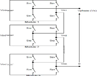
The concept of this inverter is based on connecting H-bridge inverters in series to get a sinusoidal voltage output. The output voltage is the sum of the voltage that is generated by each cell. The number of output voltage levels are 2n+1, where n is the number of cells. The switching angles can be chosen in such a way that the total harmonic distortion is minimized. One of the advantages of this type of multilevel inverter is that it needs less number of components comparative to the Diode clamped or the flying capacitor, so the price and the weight of the inverter is less than that of the two former types. Fig. 5 shows an n level cascaded H-bridge multilevel inverter. The switching angles calculation method that is used in this inverter is the same as for the previous multilevel inverters.
An n level cascaded H-bridge multilevel inverter needs 2(n-1) switching devices where n is the number of the output voltage level.
Fig 1.One phase of a cascaded H-bridge multilevel inverter
IV. DIRECT TORQUE CONTROL
Direct torque control (DTC) is one method used in variable frequency drives to control the torque (and thus finally the speed) of three-phase AC electric motors. This involves calculating an estimate of the motor's magnetic flux and torque based on the measured voltage and current of the motor.
Stator flux linkage is estimated by integrating the stator voltages. Torque is estimated as a cross product of estimated stator flux linkage vector and measured motor current vector. The estimated flux magnitude and torque are then compared with their reference values.
If either the estimated flux or torque deviates from the reference more than allowed tolerance, the transistors of the variable frequency drive are turned off and on in such a way that the flux and torque will return in their tolerance bands as fast as possible. Thus direct torque control is one form of the hysteresis or bang-bang control.
This control method implies the following properties of the control:
Torque and flux can be changed very fast by changing the references
High efficiency & low losses - switching losses are minimized because the transistors are switched only when
it is needed to keep torque and flux within their hysteresis bands.
The step response has no overshoot
No coordinate transforms are needed, all calculations are done in stationary coordinate system
No separate modulator is needed, the hysteresis control defines the switch control signals directly
There are no PI current controllers. Thus no tuning of the control is required
The switching frequency of the transistors is not constant. However, by controlling the width of the tolerance
bands the average switching frequency can be kept roughly at its reference value. This also keeps the current and torque ripple small. Thus the torque and current ripple are of the same magnitude than with vector controlled drives with the same switching frequency.
Due to the hysteresis control the switching process is random by nature. Thus there are no peaks in the current
spectrum. This further means that the audible noise of the machine is low
The intermediate DC circuit's voltage variation is automatically taken into account in the algorithm (in voltage
integration). Thus no problems exist due to dc voltage ripple (aliasing) or dc voltage transients
Synchronization to rotating machine is straightforward due to the fast control; Just make the torque reference
zero and start the inverter. The flux will be identified by the first current pulse
Digital control equipment has to be very fast in order to be able to prevent the flux and torque from deviating
far from the tolerance bands. Typically the control algorithm has to be performed with 10 - 30 microseconds or shorter intervals. However, the amount of calculations required is small due to the simplicity of the algorithm
The current measuring devices have to be high quality ones without noise because spikes in the measured signals easily cause erroneous control actions. Further complication is that no low-pass filtering can be used to remove noise because filtering causes delays in the resulting actual values that ruins the hysteresis control
The stator voltage measurements should have as low offset error as possible in order to keep the flux estimation error down. For this reason the stator voltages are usually estimated from the measured DC intermediate circuit voltage and the transistor control signals
The direct torque method performs very well even without speed sensors. However, the flux estimation is usually based on the integration of the motor phase voltages. Due to the inevitable errors in the voltage measurement and stator resistance estimate the integrals tend to become erroneous at low speed. Thus it is not possible to control the motor if the output frequency of the variable frequency drive is zero. However, by careful design of the control system it is possible to have the minimum frequency in the range 0.5 Hz to 1 Hz that is enough to make possible to start an induction motor with full torque from a standstill situation. A reversal of the rotation direction is possible too if the speed is passing through the zero range rapidly enough to prevent excessive flux estimate deviation. If continuous operation at low speeds including zero frequency operation is required, a speed or position sensor can be added to the DTC system. With the sensor, high accuracy of the torque and speed control can be maintained in the whole speed range.
V. PROPOSED SOLUTION
Various kinds of existing systems are
o Flying capacitor multilevel inverter for induction motor drive
o Diode clamped multilevel inverter for AC drive systems
o Five level inverter direct torque control strategies
o FOC systems
o Symmetric multilevel inverter systems
VII. DRAWBACKS
Various kinds of problem find out from the existing systems are,
o Flying capacitor and diode clamped type requires large number of components to achieve high voltage and
also needs isolated DC source for each call in each phase
o It will produces more torque ripples
o Five level inverter direct torque control strategies produces high torque pulsation and it is consists of high harmonics distortion
o Number of output voltage level are high when related to other. It needs large number of switching components
to inverse to the voltage rating
o Two level inverter produce high THD.
VIII. CONCLUSION
This paper has deal with a hybrid cascaded H-bridge multilevel inverter motor drive DTC control scheme. The main achievements of the proposed control method are significant reduction in the torque ripple sinusoidal output voltage and current lower switching losses and a high performance torque and flux regulation. The hybrid multilevel enables a DTC solution for high power motor devices not only due to the higher voltage capability provided by multilevel inverter but also main due to the reduced switching losses and the improved output voltage quality which provides a sinusoidal current with an output filter
REFERENCES
[1] Boldea, (Sep. 2008.) ―Control issues in adjustable speed drives,‖ IEEE Ind Electron. Mag., vol. 2, no. 3, pp. 32.
[2] G. S. Buja and R. Menis,( Apr. 2008) ―Steady-state performance degradation of a DTC IM drive under parameter and transduction errors,‖ IEEE Trans. Ind. Electron., vol. 55, no. 4, pp. 1749–1760.
[3] G. S. Buja and M. P. Kazmierkowski,( Aug. 2004) ―Direct torque control of PWM inverter-fed AC motors—A survey,‖ IEEE Trans. Ind. Electron., vol. 51,no. 4, pp. 744–757.
[4] M. Carpita, M. Marchesoni, M. Pellerin, and D. Moser,( May 2008) ―Multilevel converter for traction applications: Small-scale prototype tests results,‖ IEEE, Trans. Ind. Electron., vol. 55, no. 5, pp. 2203–2212.
[6] X. del ToroGarcia, A. Arias,M.G. Jayne, and P. A.Witting, (Feb. 2008)―Direct torque control of induction motors utilizing three-level voltage source inverters,‖ IEEE Trans. Ind. Electron., vol. 55, no. 2, pp. 965–958.
[7] M. F. Escalante, J. C. Vannier, and A. Arzande,( Aug. 2002)―Flying capacitor multilevel inverters and DTC motor drive applications,‖ IEEE Trans. Ind.Electron., vol. 49, no. 4, pp. 805–815.
[8] L. G. Franquelo, J. Rodriguez, J. I. Leon, S. Kouro, R. Portillo, and M. A. M. Prats,( Jun. 2008) ―The age of multilevel converters arrives,‖ IEEE Ind. Electron.Mag., vol. 2, no. 2, pp. 28–39.
[9] A. Haddoun, M. E. H. Benbouzid, and D. Diallo, ―A loss-minimization DTC scheme for EV induction motors,( Jan. 2007)‖ IEEE Trans. Veh. Technol.,vol. 56, no. 1, pp. 81–88.
[10] T. Ishida, K. Matsuse, T. Miyamoto, K. Sasagawa, and L. Huang, (Aug. 2002) ―Fundamental characteristics of five-level double converters with adjustable DC voltages for induction motor drives,‖ IEEE Trans. Ind. Electron., vol. 49,no. 4, pp. 775–782.
[11] F. Khoucha, M. S Lagoun, K. Marouani, A. Kheloui, and M. E. H. Benbouzid, ( Mar. 2010) ―Hybrid cascaded H-bridge multilevel inverter induction motor drive direct torque control for automotive applications,‖ IEEE Trans. Ind.Electron., vol. 57, no. 3, pp. 892–899.
[12] F. Khoucha, M. S. Lagoun, A. Kheloui, and M. E. H. Benbouzid, ―Symmetricaland asymmetrical H-bridge multilevel inverter for DTC induction motor drive automotive applications,‖ in Proc. IEEE IECON2009, Porto, Portugal, Nov. 2009, pp. 1344–1349.
[13] S. Kouro, R. Bernal, H. Miranda, C. A. Silva, and J. Rodriguez,(Nov. 2007)―Highperformance torque and flux control for multilevel inverter fed induction motors,‖ IEEE Trans. Power Electron., vol. 22, no. 6, pp. 2116–2123.
[14] F. Khoucha, K. Marouani, A. Kheloui, and M. E. H. Benbouzid, ―A minimization of speed ripple of sensorlessDTC for controlled inductionmotors used in electric vehicles,‖ in Proc. IEEE IECON2006, Paris, France, Nov., pp. 1339–134
[15] F. Khoucha, K. Marouani, A. Haddoun, A. Kheloui, and M. E. H. Benbouzid,( May 2007) ―An improved sensorless DTC scheme for EV induction motors,‖ in Proc. IEEE IEMDC2007, Antalya, Turkey, vol. 2, pp. 1159–1164.
[16] Y. S. Lai and F. S. Shyu, (Nov. 2002)―Topology for hybrid multilevel inverter,‖ IEEE Proc. Electr. Power Appl., vol. 149, no. 6, pp. 449–458. [17] S. Lu, K. A. Corzine, and M. Ferdowsi, (Jul. 2007)―A unique ultracapacitor direct integration scheme in multilevel motor drives for large vehicle propulsion,‖ IEEE Trans. Veh. Technol., vol. 56, no. 4, Part 1, pp. 1506–1515.
[18] P. C. Loh, P. C. G. H. Bode, and P. C. Tan, (Jan. 2005)―Modular hysteresis current control of hybrid multilevel inverters,‖ IEE Proc. Electr. Power Appl.,vol. 152, no. 1, pp. 1–8.
[19]M. Manjrekar and T. A. Lipo, ―A hybrid multilevel inverter topology for drive application,‖ in Proc. IEEE APEC1998, Anaheim, CA, Feb., pp. 523–529.