Z –Transform, Difference Equations and Its
Approach to Digital Signal Processing
*N.D.Narkhede1, *Dr.J.N.Salunke2,*Neha Narkhede3
Associate Professor, J.T.Mahajan College of Engineering, Faizpur, Jalgaon, India*1
Director of School of Mathematical Sciences SRTM University Nanded, India*2
Research scholar, PVGCOET, Pune, India*3
ABSTRACT: This Research Paper first, briefly explains Z-transform, difference equation and differential equation. It
then takes up difference equation, system function and demystifies its i m p l e m e n t a t i o n i n digital f iltering operations. This work further highlights digital filters with focus on finite impulse response (FIR) and Infinite impulse Response (IIR) filter, basic comparison between IIR and FIR are also highlighted. Finally, choice of a filter for a particular purpose is discussed.
KEYWORDS: Z-transform, difference equation, system function, Finite Impulse Response(FIR), Infinite Impulse
Response(IIR).
I. INTRODUCTION
With the explosion of digital communication and media, the need for methods to analyze and process digital data is becoming more important than ever. According to Professor. Todd K. Moon, Z-transform like the Laplace transform, is an indispensable mathematical tool for the design, analysis and monitoring the stability of a system[1]. Z-transform converts a sequence {x[n]}, into a function X(z)of an arbitrary complex-valued variable z. This is very important as complex functions are easy to manipulate than sequence. Mathematical descriptive relationship of input-output of a system if formulated either in the time domainor in the frequency domain. Time domain system analysis methods are based on differential equations which describe the system output as a weighted combination of the differentials (i.e the rates of change) of the system input and output signals. Frequency domain methods, mainly the Laplace transform, the Fourier transform, and the z-transform, describe a system in terms of its response to the individual frequency constituents of the input signal.[3]. This research reveals that the Z-transform determines the stability of a system as description and representation of a system in the frequency domain reveals valuable insight into the system behavior and stability. In addition to this, the transient and the steady state characteristics of a system can be predicted by analyzing the roots of the z-transform, which are so-called poles and zeros of a system. Hence Z-transform is highly utilized in the digital signal processing and digital filters analysis.[4]
II. SYSTEM FUNCTION
The linear convolution of two sequences x(n) and h(n) can be expressed as
( ) = ( )∗ ℎ( ) (2.1)
Taking Z-Transfor the convolution becomes multiplication. Thus
( ) = ( )( ) (2.2)
Here H(z) is known as system or transfer function. Note that H(z) is Z-transform of h(n); where h(n) is an impulse response of the system. Thus the system is characterized by H(z) can be obtained from its difference equation. By definition of Z-transform,
( ) = ∑ ℎ( ) (2.3)
Alternatively, system function H(z) is defined as the ratio of Z-transform of output signal y(n) and Z-transform of input signal x(n).[6]
As the Linear Time Invariant system is described by linear constant coefficient difference equation as:
( ) = − ∑ ( − ) + ∑ ( − ) (2.4)
Taking Z-transform of (2.4)
( ) = − ( ) + ( )
Or ( ) = ( )
( )=
∑
∑ (2.5)
The system function defined in (2.5) contains both poles and zeros and hence the corresponding system is also called a pole zero system, with N poles and M zeros.[5]
If H(z) has poles at z = , ,………. and zeros at z = , ,………….. , then H(z) is factored and represented as
( ) = ( ( )()( )……()…( )) (2.6)
Where is the zero and is pole and K is the gain factor. They may be real or complex. The information contained in Z-transform is easily displayed as pole-zero plot.
An important feature of the pole-zero plot is the unit circle defined by |z|=1. This unit circle of pole-zero plot playsan important role in the analysis and design of discrete time system. From its location we can interpret the frequency response of the system and its stability. defined in (2.5) are system parameters of digital filters. In fact by
finding and , we determine H(z) and ultimately we have designed the digital filter.[2]
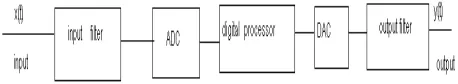
A simplified block diagram of a real time digital filter with analog input and output signal is shown in figure.
A. WHAT IS A SAMPLED SYSTEM?
Digital filters are by essence sampled systems. The input and output signals are represented by samples with equal time distance. A typical sampled system is as depicted in figure 2.1above:
An analog signal is converted to a digital form in an A/D. The digital signal is processed somehow.
The processed digital signal is converted to an analog signal for the use in analog world.[2]
III. DIFFERENTIAL, DIFFERENCE EQUATIONS AND DIGITAL FILTERS
A. DIFFERENTIAL EQUATION
This is not to be confused with difference equation vice versa. A differential equation is a mathematical equation that relates some function with its derivatives. And their derivatives represent their rates of change, and the equation defines a relationship between the two. The input and output of a continuous system which are related by differential equation are solved by Laplace transform technique. However, applicable to sampled system are Z-transform techniques which solve the difference equation that forms the relationship between its input and output.[1]
B. DIFFERENCE EQUATION
A difference equation is an equation which expresses a relation between an independent variable and the successive values of the dependent variable. This represents a Linear Time Invariant (LTI) system and obeys all its usual properties. Therefore, difference equation is to discrete signal processing what the differential equation is to analogue signal properties. It is used to describe operation of discrete time system.[8]
C. DIGITAL FILTERS
Basically a digital filter is a LTI discrete system. The design of an IIR filter for a given specification is nothing but finding filter coefficients and as per specification. A filter is a device which is used to change the waveform, amplitude and phase of a signal. A digital filter is a mathematical algorithm applied in hardware or software that works on the digital input signal to produce the output of a signal for the purpose of achieving filtering. [4]
This is a system (sampled system) that performs mathematical operations (Z-transform techniques) on a sampled, discrete-time signal to suppress or boost certain aspects of that signal and it is principally implemented in digital signal processing (DSP) devices. A digital filter system usually consists of an analog-to-digital converter to sample input signal, followed by a microprocessor and some peripheral components such as memory to store data and filter coefficients etc. Finally, a digital-to-analog converter to complete the output stage and Program Instructions (software) running on the microprocessor implemented by the digital filter by performing the necessary mathematical operations on the numbers received from the ADC (as simplified in the above figure 2.1). [3] However, it is worthy to note here that analogue filters can yield similar output as digital filters, only that digital filters can achieve far superior results. It is important also that digital filters are characterized by its transfer function, or equivalently, its difference equation as it is the case in this research work.
3.3.1 Difference Equation implementation in Digital filters
The difference equation is a formula for computing an output sample at time based on past and present input samples and past output samples in the time domain. Hence the general causal Linear Time Invariant (LTI) difference equation is written as shown in equation (2.4)
As a specific example, the difference equation:
0.89y(n -1) --- (3.1)
specifies a digital filtering operation, and the coefficient sets (0.03,0.004) and (0.89) fully characterize the filter. In this example, we have M=N=1. When the coefficients are real numbers, as in the above example, the filter is said to be real. Otherwise, it may be complex and defined as shown in equation (2.4).
This forms the basis for design of digital filters. With this, digital filters are categorized into two broad classes:
Recursive Non-recursive
Hence based on above equation, any filter having one or more feedback paths (N>1) is called Recursive. Specifically, the coefficients are called thefeed forwardcoefficients and the coefficients are called the feedback coefficients. A filter is said to be recursive if and only if ak is not equal to zero for some k>0. Recursive filters are also called infinite
impulse response (IIR) filters. It is important to note that its impulse response of an Nth-order FIR filter lasts for N+1 samples, and then dies to zero.[7] This means that for a finite number of sample intervals, it finally settles to zero. But when there is no feedback (ak=0, for all k>0) , the filter is said to be a non-recursive or finite-impulse-response (FIR)
digital filter. It is finite because its impulse response is of finite duration. This is in contrast to recursive – infinite impulse response(IIR) filters which have internal feedback and may theoretically continue to respond indefinitely. The impulse response of a digital filter is the output sequence from the filter when a unit impulse is applied at its input. (A unit impulse is a very simple input sequence consisting of a single value of 1 at time t=0, followed by zeros at all subsequent sampling instants).[8]
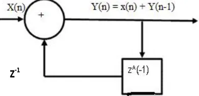
Therefore Recursive filters are efficient way of achieving a long impulseresponse, without having to perform a long convolution. They execute very rapidly, but have less performance and flexibility than other digital filters. Recursive filters are useful because they bypass a longer convolution. Since this impulse response is infinitely long, hence recursive filters are called infinite impulse response (IIR) filters. In effect, recursive filters convolve the input signal with a very long filter kernel, although only a few coefficients are involved. [2] Below diagrams illustrates non-recursive and non-recursive digital filters:
Fig 3.1 Non-Recursive digital Filter(as adapted from digital signal processing by Zeyad Al-Hamdany)
Fig 3.2 Recursive digital filter
Z-1
D. BASIC DIFFERENCES BETWEEN INFINITE IMPULSE RESPONSE (IIR) – RECURSIVE AND FINITE IMPULSE RESPONSE (FIR) – NON-RECURSIVE FILTERS
Efficient Memory utilization and throughput: The obvious main difference between IIR filters and FIR filters is that an IIR filter is more compact in that it can usually achievea prescribed frequency response with a smaller number of filter coefficients imply less storage requirements and faster calculations and a higher throughput. Therefore, generally IIR filters are more efficient in memory and computational requirements than FIR filters.[9]
Stability: FIR filter is always stable, whereas an IIR filter can become unstable and care must be taken in the design
of IIR filters to ensure stability. An FIR filter will be stable no matter how it is synthesized or implemented as it has no feedback. On the other hand, an IIR filter with improperly placed poles can’t be made stable no matter how it is implemented.
Math Register Size: IIR takes up more register size than FIR during peak signal processing. The peak math value for
IIR can range from 1.0 to 10,000 or even higher.[2] A filter’s peak math value is a strong function of the polynomial it is based on and its selectivity. The more selective the filter, the higher the math values.
Implementation structures: FIR filters are usually implemented as nth order polynomials. IIR filters on the other
hand, can be implemented this way, but only if a floating point processor is available. If using a fixed point processor, an IIR filter must be implemented as a series of second order. This is to guard against overflow during peak math value which ishighly forbidden which can lead to its abnormal behavior.[2]
IV. CONCLUSION
This research work has thoroughly x-rayed and anatomized the beauties of Z-transform application in solving difference equations which form the backbone of digital filters operations. It is also emphatic to note that IIR filter is neither totally superior nor worse than FIR filter. Each has its suitability, and the protects overall requirements and cost determine choice.
Therefore, one’s choice for a particular digital filter be it IIR or FIR, does not holistically make the chosen filter the best solution as each filter which is preferred in one solution, may be feast thought or an another. This is because a lot of factors are put into consideration (as discussed above) such as cost, delay or latency, stability etc. in choosing one digital against another.
REFERENCES
[1] Corrigan D.(2012).DifferenceEquations and digital filters. Retrieved May 10,2015 fromhttp://www.mee. tcd.ie/~corrigad/3c1/DSP1_2012_students.pdf.
[2]Nwagu K ChikezieO k o n k w o O b i k w e l u , D i g i t a l s i g n a l p r o c e s s i n g : R o l e o f Z T r a n f o r m a n d D i g i t a l f i l t e r s I J E T T C S v o l . 4 , J u l y – A u g . 2 0 1 5 { p a g e s 8 1 - 8 4 ]
[3]Digitalfilterresponse.RetrievedApril13,2015from https://www.cis.rit.edu/class/simg713/notes/chap7-digital-filter.pdf
[4]Difference equation andz- transforms. Retrieved April 08,2015 from
http://www.newagepublishers.com/samplechapter/001401.pdfsite).
[5] Mathews J.H. Howell R.W.(2012). Modulefor Introduction to Filtering. Retrieved May04,2015 fromhttp:// mathfaculty.fullerton.edu/mathews/c2003/ ZTransformFilterMod.html
[6] Smith S. W. (1997).The scientistand Engineer`s guidetodigitalsignal processing.Retrieved May08,2015
[7]Typesof Digital Filters.Retrieved May 10,2015fromhttp://ideasdsp. blogspot.com/2009/07/types-of- digital-filters.html
[8]FesslerJ.(2004,May27,13:18)Chapter8.Designof digital filters(studentversion). RetrievedMay 16,2015fromhttp://web.eecs.umich. edu/~fessler/course/451/l/pdf/c8.pdf
[9]IowaHills Software (2013).DigitalandAnalog filters.RetrievedMay17,2015fromhttp:// iowahills.com/ A8FirIirDiff erences.html