Vol. 7, Issue 5, May 2018
Tuning of PID Controller for Temperature
Loop
Vikas Karade1, Sagar Sutar2, Ambadas Shinde3
Assistant Professor, Department of Instrumentation Engineering, PVPIT Budhgaon (Sangli), Maharashtra, India1
Assistant Professor, Department of Instrumentation Engineering, PVPIT Budhgaon (Sangli), Maharashtra, India2
Assistant Professor, Department of Electronics Engineering, PVPIT Budhgaon (Sangli), Maharashtra, India3
ABSTRACT: This paper proposes a PID controller for Serial Input Serial Output (SISO) process which is used to control the temperature of a tank. Delta PID controller was used to control the temperature of water tank. The mathematical model of water tank is developed. The theoretical model and the model prepared by using parameter estimation method are compared. Process identification tool box form MATLAB was used for finding model output. Ziegler-Nichols (ZN) method was used to tune the PID controller and results are verified.
KEYWORDS: PID controller tuning, proportional controller, Delta PID, Temperature control
I. INTRODUCTION
The PID controller is combines the functions proportional controller, integral controller & derivative controller. To achieve the better stability to avoid the small disturbances, proportional controller is most frequently used. The proportional controller produces output which is proportional to the error. Integral controller considers previous error to generate the present output. Integral controller produces an output that depends on the magnitude of error. Finally, derivative controller considers the future values and calculates the output according to the slope of error. The derivative function (rate action) provides compensation for changes in load which take place rapidly [4][5].
Ziegler-Nichols (ZN) method is used to tune PID controller. This technique is also called as ultimate cycle method. It is based on adjusting closed loop until steady oscillation occurs [4].
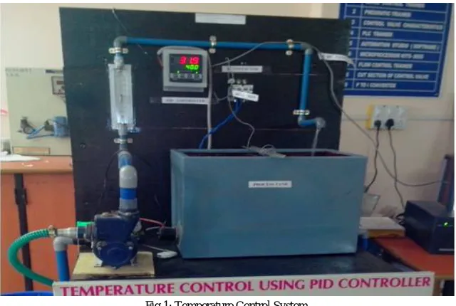
Figure 1 shows temperature control loop system. Thermostatic control of temperature is the very commonly used method in temperature control of dry air. In the temperature control loop, temperature is controlled by varying the voltage applied across the heater coil, thereby varying the current flowing through coil. The objective of this system is to control temperature of water inside the temperature controlled tank at desired set point.
A 2KW heater coil is used to heat up the water inside the temperature controlled tank. Temperature sensor RTD (PT100) with temperature sensor is used to sense temperature given to PID controller as measured variable (M.V.). This input is compared with set point (S.P.) & error signal is generated. The error signal generated is fed to Delta PID block & output is compared with controller. Controller output is then given to thyristor (0-100% to 4-20mA), which converts the electric input signal (4-20mA) into correspondence electric output signal (0-230 VAC, 10 A).
This power output is fed to heater element of temperature control tank, depending upon the power variation the temperature of water increases or decreases respectively.
Consider the process in which liquid is flowing into the tank at some rate fin and out of the tank at some rate
fout as shown in figure 1. The sensor is inserted in the system to provide controlling signal, which will control the loop.
The output signal from the sensor is used as an input to a controller. The controller compares the required temperature, which is called the Set Point (SP), with actual temperature in the tank and generates an output signal which is feed to the heater [1].
Using MATLAB model is developed by using practical results. The response obtained from practical set up and results from simulation are compared.
Fig 1: Temperature Control System
The paper is organized as follows. Section II describes related work, different techniques used to control temperature. Section III describes basics of PID controller and its importance. Section IV Mathematical Modelling of temperature control process model is explained. The number of process variables was described in same section. Section V presents experimental results showing results of images obtained by MATLAB simulink and real process.
II. RELATEDWORK
Controlling the temperature is most crucial phase in any process industry and the temperature is most important parameter [1]. Different authors have developed different models of temperature loop control. The PID is automatically tuned in systems those were controlled by Delta PID controller [1]. They have developed a model of simple water heating system. First order, time delay model is derived using MATLAB and the response is compared with actual system by Haresh et al. [10]. For demonstrating the performance of proposed method it is applied to three SISO processes. First order plus dead time model of temperature process in laboratory is found using PRBS input. In his work PID controller tuning method for SISO process is implemented by Sagar et al. [11]. Enxiang et al. [13], in his paper presented self tuning PID control system to solve common problems in process industrial production, controller. The parameter identification was done online using their system that can adjust parameters automatically.
III.PIDCONTROLLER
Vol. 7, Issue 5, May 2018
u(t) = K e(t) + ∫ e(τ)dτ+ T ( ) … … … (1)
PID structure is as shown in eqn. 1 Error signal e(t) is used to generate the PID actions to form control signal u(t)
applied to the plant model [1].
IV. MATHAMATICALMODELLING
Modelling is the mathematical representation of a given system. The basis of mathematical models is physical and chemical laws such as laws of conservation of mass, energy and momentum. Assumptions plays important role to build the model. The model developed down to microscopic detail would be very complex and impractical to solve. So, assumptions are laid to get good enough solution. Degree of freedom should be zero in order to find the solution. Assumptions:
1. Perfect mixing of the component with temp. T. 2. The inlet & outlet flow rates are equal.
3. Density (ƍ) & heat capacity (C) are assumed to be constant-thus temperature dependence is neglected. 4. Heat loss is negligible.
We consider energy balance because thermal effect predominate the system
Energy balance equation.
Rateof Accumulation Ofenergy = Rateof energyin (convection)
- energyRateofout +
rateofheat additiontosystem
fromsurrounding +
rateofwork performedonasystem
bysurrounding
dUint
dt =−∆ WH + Q … … … (2)
For pure flow or moderate pressure the internal energy is approx equal to enthalpy (heat content in the steam)
(dUint) = dH = CdT … … … (3)
Where,
UintInternalenergy H − Enthalpy
C−Constant
Depends on temperature
Total internal energy of liquid in tank can be expressed as a product of internal energy per unit mass in the tank
Uint =Ûint. ƍ. C... (4)
An expression for rate of internal energy accumulation can be derived from equation (3)
dUint
dt =.ƍ. C. V dT
dt… … … (5)
We derive the expression for enthalpy term that appears an right sight of the eq.(2) Suppose the liquid in the tank is constant temperature T has enthalpy H the integration equation (3),
dH = d .
C. dT
H−Href = C(T−Tref) … … … (6)
Assume,
Href = 0
H = C(T−Tref) … … … (7)
Similarly for the inlet flow,
Hi = C(Ti−Tref) … … … (8)
Put equation (5) & (6) in equation (2) Which gives desired dynamic model of stirred tank heating system.
V.ƍ.C. = wc(Ti−T) + Q … … … … . (9)
Tref is cancelled because heat capacity C assumed as constant & thus independent of temp.
Degree of freedom for this model gives three parameter V.ƍ.C. & four variables Ti, T, W, Q & one equation i.e. no. [1]
Take Laplace transform of equation no (9). Dynamic model of temperature process can be described as first order linear transfer function.
Ts
Qs=
K
1 +τ e … … … . (10)
For control purpose: Manipulated Variable Q Disturbance Variable Ti, W [9]
V. EXPERIMENTALRESULTS
PID Mode:
1. Set Point 50°C
2. Controlling Time 10 Sec. 3. Flow Rate 40 lph
I/P In Sec O/ P in °c I/P In Sec O/ P in °c
10 40.1 110 47.2
20 40.2 120 47.8
30 42 130 48.3
40 42.7 140 48.6
50 43.6 150 49.1
60 44.2 160 49.5
70 44.9 170 49.9
80 45.6 180 50.0
90 46.1 190 50.0
Vol. 7, Issue 5, May 2018
Output of Delta PID controller of temperature loop for set point 50 is as shown in figure 2.
Fig. 2: PID Mode
Figure 3 shows Transfer function for temperature control system. Here ZN method is used to find the PID parameters.
Fig. 3: Process Model
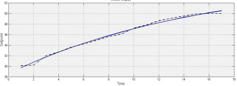
Figure 4 shows response of best fit for designed system. The response is obtained by using MATLAB identification toolbox. The model output obtained from real time values.
For Temperature control system, Response time 17.6 Sec, Rise time 11.9 Sec, Settling time 41.8 Sec, Overshoot 6.77 % as shown in figure 5.
Fig. 5: Tune Values Using ZN Method
VI. CONCLUSION
Model of temperature control system is obtained by using energy balance equation. PID controller used for this loop is tuned by Zeigler Nicholas method. Dynamic parameters of process are obtained by using MATLAB. Parameters obtained by simulation as well as mathematical calculation are nearly same.
REFERENCES
[1] V. L. Karade, A. B. Shinde, S. S. Sutar, “PID Based Temperature Controller”, International Journal of Innovative Research In Electrical, Electronics, Instrumentation And Control Engineering”, Vol. 4, Issue 5, pp. 395-397, 2016
[2] Dingyu Xue, Yangquan Chen, Derek P. Athereton, “Linear Feedback Control”
[3] G. Stepnopoulos, “Chemical Process Control: An Introduction To Theory & Practice”, Prentice Hall Of India. [4] C. D. Johnson, “Process Control Instrumentation Technology”, Seventh Edition, Pearson Education, New Delhi 2003. [5] T. Vander, “Study Of Temperature Control For Engr, 315 Control System” Butterworth Heinemann Ltd., 1995. [6] Eckman P. Donald, “Automatic Process Control”, Wiley Eastern Ltd, New Delhi.
[7] B. Wayne Bequette, “Process Control: Modeling, Design & Simulation”, PHI Learning Pvt. Ltd, New Delhi, 2010
[8] William L. Luyben, “Process Modelling, Simulation and Control For Chemical Engineers”, Second Edition, Mc-Graw Hill Publication. [9] Dale E. Seborg, Thomas F. Edgar, Duncan A. Mellichamp, “Process Dynamics And Control”, Second Edition, Willey Publication. Manual:
Econ Dt 9812.
[10] Haresh A. Suthar, Dr. Jagrut J. Gadit, “Modeling And Analysis Of Simple Water Heater System”, International Journal Of Electrical And Computer Engineering (IJECE), Vol.1, No.1, pp. 49-52, 2011
[11] Sagar Sutar, Dr. D. K. Maghade, “Tuning PID Controllers For Desired Closed Loop Performance Specifications” International Conference On Innovations In Electronics And Communication Engineering (ICIECE), 2013
[12] Kadir Erkan And Seda Postalcloglu, “Experimental Auto Tuning PID Control Of Temperature Using Microcontroller” IEEE, pp. 266-269, 2005