Underwater Wireless Optical Communication
H.Srinivas Rao 1, Madhuri Vishwamithra M.S 2, Sreelakshmi.T.V[3],Sindhu.M[4]
Department of CSE & ISE, City Engineering College, Doddakalsandra, Bangalore, India
ABSTRACT: The Wireless communication technology has became a part of our daily life. The earth is covered by 75% of water. With the intensive development in technology, Underwater wireless optical communication are the best emerging solutions for broadband links in oceans and seas. UOWC plays a vital role in tactical surveillance, pollution monitoring, oil control, climate change monitoring, offshore study, military field, scientific field and oceanography research. The signals that carries the digital information through an underwater channel are not radio signals, since electro-magnetic waves propagate only over extremely short distances. Instead, acoustic waves are improvised, which can be propagated over long distances. This paper provides an in-depth outlook of recent trending advancements in UOWC and therefore it’s mainly focus is to understand the reliability and feasibility high data rate underwater optical links. This research not only provides exhaustive research in underwater optical communications but also aims to implement the new ideas that would help in the development of the UOWC.
1. INTRODUCTION
To achieve the underwater optical wireless communication in the rapidly growing military and commercial fields it demands reliable, safety, flexible, scalable and practical multi access network. In order to achieve the above demands there are two types of transmission available, acoustic transmission and optical transmission. The acoustic transmission is one of the technique used where its bandwidth ranges from 10-100, due to its high latency and long range communication it causes problems in synchronisation and multi access technique. In order to overcome its disadvantage like low bandwidth and higher transmission losses optical signals are introduced. In compare with the acoustic transmission wireless optic communication overcomes above defects and provides three main advantages like higher bandwidth, higher security and low time latency[1][2].
.
Fig: 1 The line of sight communication description.
used in order to provide a high data rate. The link performance is analysed using the above kinds. From analysis it is absorbed that as the water absorption increases the communication performance decreases[3]
.
II.PROPERTIESANDCHARACTERISTICSOFUWOC.
The optical pulses propagating in an aquatic medium suffer from attenuation, and widening in spatial, angular, temporal, and polarization domains. The above factors are wavelength dependent. where absorption is the process in which photons collides with the water molecules and thermally losses its energy[4].where as scattering is the form where photon alter its direction and hence some amount of energy gets lost. Energy loss due to absorption ( ) and
scattering effect β(λ) ,the extinction coefficient ( )[5].
.
( ).= ( )+ β(λ). (1)
It is clear that an increase in turbidity gradually increases the extinction coefficient, where the coefficient ranges from less than 0.1 m-1 for pure water till more than 2 m-1 for turbid harbour water. The propagation loss factor as a function of distance z is given below
Lpr (λ,z) = exp[-c(λ)z] (2)
III.UNDERWATERWIRELESSOPTICALLINKS
In this we are going to use line of sight link, A modulating reflector link, Reflective link. Were apart from these we use bit error detection also.
i) Line Of Communication links:
The line of communication link is one of the general and most commonly used communication between the two points in optical wireless communication. As it s shown in fig 2.Transmitter deflects the light in direction of receiver. The signal that reaches the receiver is obtained by multiplying transmitting power, telescope gain and losses and is gain in ref 2 as
R_los = PT ηT ηR LPr ( λ, d ) ARec Cosθ (3)
Cosθ 2πd2(1-cosθ0)
Fig:2 The Line Of Sight Scenario.
Where PT is the average transmitter optical power, ηT is the optical efficiency of the transmitter, ηR is the optical
beam divergence angle. Here when divergence angle becomes very narrow that means (θ0<<π/120) then the above
equation 1 becomes
R_los = PT ηT ηR LPr (λ , d ) ARec Cosθ (4)
cosθ π(d tan θ0)2.
ii) Modulating reflector communicating link
The modulating reflector link is used when one party has more resources than another one for example submarine has more resources like more energy, payload and the lifting capacity than the diver. A modulating reflector communication link combines an optical retro reflector and optical modulator to allow optical communications. In this the interrogator sits at one end and the small modulating optical optic retro reflector sits at the remote end. The retro reflector successfully reflects the beam back to interrogator sent by it. The received power in this scenario is given by
PR_los = PT ηT ηRec ηRetro Lpr (λ, 2d) [ARec Cosθ] X [ARec Cosθ] (5)
COSΘ 2ΠD2(1-COSΘ0) Π(D TAN Θ0RETRO)
2
Where ηretro is the optical efficiency of retro reflector, θ is the angle between the perpendicular to receiver plane and the
transmitter-receiver trajectory, ARetro retro reflector aperture area ,and θ0retro is retro reflector beam divergence angle
Fig:3 The Modulating retroreflector communication scenario
iii) Reflective communication link
In some scenarios the line of sight is not available due to obstruction ,misalignment and random orientation of transceiver .In order to overcome this reflective communication link can be used. In this scenario, the laser transmitter
emits a cone of light defined by inner outer angle θmin and θmax,inthe upward direction.
Where θi is angle of incidence and θt is angle of transmission.(the latter is derived from the former using the snell’s law).
Where the light reached the water – air surface it illuminates angle and a small amont is reflected back in accordance with its reflectivity.
Due to refractive index of air is lower than the water total internal reflection can be achieved.
When the transmitter is at depth h, then the illuminated surface with equal power density at depth x can be derived by
Fig:4 The reflection communication scenario
IV.BITERRORRATECALCULATION
In general the bit error rate is the number of bit errors per unit time. In this technique the receiver is based on the emerging technology of silicon photomultipliers[6].These photo detector devices are fabricated in the form of arrays of photo diode that are operated in Geiger mode to create a photon counting device. If we assume the large number of photons are received then according to the central limit theorem ,poison distribution can be approximated by Gaussian distribution and the BER is given by[7].
BER = {
√ ( ) ( )
}
V. DISCSSION AND CONCLUSION
The three types of link models can be used to design sophisicated network. It is clear that the los narrow beam divergence provides max range.
The best option is to use los with a wide beam divergence .If obstructions between two platforms blocks the los and reflective communication link is preferred. when one side we have more resources than the other side in the link the the modulated retro reflector is the best option.
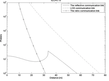
Here, we are simulating the performance of the three links, using the practical values for clear ocean water with the extinction coefficient of 0.15 m-1.The values of simulation parameters are given in the table 1.
Parameter Typical value
Extinction co-efficient, clear ocean(m-1) 0.1514
Refractive index 1.33643
Critical angle(deg) 48.44
Transmission wavelength 532
Optical efficiency of retroreflector 0.9
Optical efficiency of transmitter 0.9
Optical efficiency of receiver 0.9
Average transmitter power(W) 10
Pulse duration (ns) 1
Data rate (Mbit/s) 0.5
Receiver aperture area (m2) 0.01
Retroreflector aperture area (m2) 0.01
Transmitter inclination angles θmin, θmax(deg) 0,68
Dark counting rate (MHz) 1
Background counting rate (MHz) 1
Transmitter depth h (m) 20
Receiver depth x (m) 20
Extinction co-efficient for turbid harbour 2.19
Counting efficiency (%) 16
Table1: Values of simulation parameters, Lets assume diffraction limited divergence angle is less than θretro
By theoretical and practical evidences from fig 4 we can conclude that a single LOS under water link using laser transmitter and receiver it results in relatively higher photon count for a given sensor node separation in compared to reflective or retroreflector link.
Fig. 4.Graph showing number of received photons as a function oftransmitter-receiver separation for clean ocean water with extinction coefficient equal to 0.15 m−1.
According to Fig 5 we can conclude that for reflective link node separation 40 m then BER values will be 10-4.While same BER values will be obtained in LOS link and a retroreflector links where node separation is at 50m and 60m respectively. By this we can assume BER values can be achieved for short ranges.
V.CONCLUSION
The results presented about indicate that networks based on underwater optical wireless links are feasible at high data rates for medium distances, up to a hundred meters. Additional improvement to placing multiple relay nodes between the chief network nodes, messages could traverse very long distances despite severe medium-induced limitations on the transmission ranges of individual links. A hybrid communication system can provide high data rate transmission by using optical transceiver. When the water turbidity is high or the distance between the terminals is large, the system can be switch to low data rate using the acoustic transceiver, thereby increase in the average data rate and availability. Moreover the similarities between result of numerical simulations and analytical expressions verified the accuracy of our derived analytical expressions for the system BER. Finally, we should emphasize that although all of the numerical results of this paper are based on lognormal distribution ,most of derivations can be utilized for various fading statistical distribution.
REFERENCES
[1] H.Kaushal and G.Kadoum, ”Underwater optical wireless communication”, IEEE Access,vol:4,pp.1518-1547,2016.
[2] B.M Cochenour, L.J.Mullen, and A.E Laux, ”Characterization of the beam-spread function for underwater wireless optical communication links”, IEEE J. Ocean Eng, vol.33 , no.4,pp. 513-521,oct 2008 .
[3] Shlomi Arnon, “Underwater optical wireless communication network” January 2010.
[4] P.Vijaya Kumar, S.S.K.Praneeth,Romarsha.B.Narender, “Analysis of optical Wireless Communication for underwater Wireless Communication”, International Journal of Scientific & Engineering Research Volume 2, Issue 6,June-2011, ISSN 2229-5518.
[5] D.Kedar and S.Arnon, “Subsea ultraviolet solar-blind broadband free-space optics communication,” Opt. Eng. 48(4), 046001 (2009).
[6] P.Eraerds, M.Legre, A.Rochas, H.Zbinden, and N. Gisin, “SiPM for fast photon-counting and multiphoton detection,” Opt. Express 15(22),14539-14549(2007).