Multilevel Inverter for Eliminating Harmonics
in Line To Line Voltage Using Genetic
Algorithm
P.Senthilkumar, Gayathri Katuri
Assistant Professor, Department of Electrical and Computer Engineering, College of Engineering and Technology
Mizan-Tepi University, Ethiopia.
Assistant professor, VMKV Engineering College, Chinna Seeragapadi, Periya Seeragapadi, Tamil Nadu, India
ABSTRACT: This paper the total harmonic distortion (THD) minimization of the multilevel inverters output voltage is discussed. The approach in reducing harmonics contents in inverters output voltage is THD elimination. The switching angles are varied with the fundamental frequency so the output THD is minimized. In three-phase applications, the line-voltage harmonics are of the main concern from the load point of view. In this paper, using the genetic algorithm, a THD minimization process is directly applied to the line-to-line voltage of the inverter. Genetic (GA) algorithm allows the determination of the optimized parameters and consequently an optimal operating point of the circuit and a wide pass band with a unity gain is obtained. This paper is based on a 11 level MLI the proposed system also able to obtain an optimal operating point using GA. To verify the simulation a 11 level cascaded-H-bridge-inverter-based simulation is presented.
KEYWORDS: Continuous Genetic Algorithm (CGA); Multi-level Inverters; Optimized Harmonic Stepped Waveform (OHSW); Particle Swarm Optimization (PSO).
I. INTRODUCTION
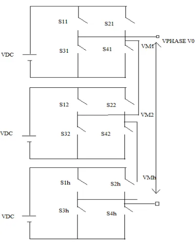
structures. In [1-4] depicts one aspect which sets the cascaded H-bridge apart from other multilevel inverters is the capability of utilizing different DC voltages on the individual H-bridge cell, which results in splitting the power conversion amongst higher-voltage lower-frequency and lower-voltage higher frequency inverters. An alternate method of cascading inverts involves series connection of two three-phase inverters through the neutral point of the load. An advantage of this approach is that isolated sources are not required for each phase. It should be noted that cascaded inverter system can be considered from a number of different viewpoints. Considering the cascaded inverter to be one unit, it can be seen that a higher number of voltage levels are available for a given number of semiconductor devices. Capacitors batteries and or renewable energy voltage sources can be used as a DC voltage sources. The general function of this multilevel inverter is the same as that of the other two previous inverters. This multilevel inverter using cascaded inverter with SDCS synthesis a desired voltage from several independent sources DC voltages which may be obtained from batteries, fuel cells, all solar cells. This configuration recently becomes very popular in AC power supplies and adjustable speed drive applications. This new inverter can avoid extra clamping ten diodes or voltage balancing capacitors. A single phase m-level configuration of such an inverter is shown in Figure 1. Each SDCS is associated with the single phase full bridge inverter. The AC terminal voltages of different level inverters are connected in series. By different combinations of the four switches, S1-S4, each inverter level can generated three different voltage outputs, +Vdc, -Vdc and zero. The AC output of each of the different level full bridge inverters are connected in series such that the synthesis voltage waveform is the sum of the inverter outputs. In this topology, the number of output phase voltage level is defined by m=2s+1, where s is the number of DC sources.
Figure 1 Cascaded Multilevel Inverter
II. HARMONICREDUCTIONTECHNIQUE
Vo(wt)={ao+∑(ancos nwt+bnsin nwt)}sin nθ (1) n =1,2,3...
The output voltage expression For five level inverter is found as
Vo(wt) =Σ (4Vdc/nп) (cosnα1 + cosnα2 + cosnα3+cosnα4) Sin nθ (2) n=1,3,5
Here the angles α1, α2, α3 and α4 are turn on angles for the switches of five level inverter. And these angles are used to reduce the harmonics which are present in output voltage. We can assume these angles to obtain symmetrical output voltage. But the calculated THD of output voltage is high for these angles. If we correctly select these angles, we can reduce THD in output voltage. For that we can use MATHCAD to find these angles. The proposed system analyses the frequency spectrum and Voltage control. In conduction angle control the lower order harmonics are reduced. By adjusting the turn on angle to various levels, it is possible to reduce the lower order harmonics. And the efficiency, power factor is improved. The Fourier expression is also obtained for the output voltage of five-level inverter.
For five level inverter
Vo (wt) = Σ (4Vdc/nп) (cosnα1 + cosnα2 + cosnα3+cosnα4) Sin nθ (3) n=1,3,5...
Where Vdc is the supply dc voltage.In the above expression there are four angles related to output voltage. So it is possible to reduce four odd harmonic because even harmonics are not present in output voltage. But our aim is to control the output voltage and reduction of harmonics. From the above expression, four equations are formed and the four angles are found. If the no of levels are increased, it is not easy to find the switching angles to remove particular order of harmonics for that ELIMINATION THEORY is used. The modulation index is chosen as 0.8 for low THD. In five level inverter to reduce the LOH from the output voltage, the turn-on angles are calculated from the output voltage equation.
III. GENETICALGORITHM
Professor John Holland in 1975 proposed an attractive class of computational models, called Genetic Algorithms (GA), that mimic the biological evolution process for solving problems in a wide domain. Genetic Algorithms has three major applications, namely, intelligent search, optimization and machine learning. Currently, Genetic Algorithms is used along with neural networks and fuzzy logic for solving more complex problems. Because of their joint usage in many problems, these together are often referred to by a generic name: “soft-computing”. A Genetic Algorithms operates through a simple cycle of stages:
i. Creation of a “;population” of strings ii. Evaluation of each string
iii. Selection of best strings and
iv. Genetic manipulation to create new population of strings.
Each cycle in Genetic Algorithms produces a new generation of possible solutions for a given problem. In the first phase, an initial population, describing representatives of the potential solution, is created to initiate the search process. The elements of the population are encoded into bit-strings, called chromosomes. The performance of the strings, often called fitness, is then evaluated with the help of some functions, representing the constraints of the problem. Depending on the fitness of the chromosomes, they are selected for a subsequent genetic manipulation process. It should be noted that the selection process is mainly responsible for assuring survival of the best-fit individuals. After selection of the population strings is over, the genetic manipulation process consisting of two steps is carried out. In the first step, the crossover operation that recombines the bits (genes) of each two selected strings (chromosomes) is executed. Various types of crossover operators are found in the literature. The single point and two points crossover are obtained.
OPTIMIZATION BY GENETIC ALGORITHM
the crossover and the mutation.
IV. SOMECOMMONMISTAKES
Figure 2.Simulation for 11 levels MLI
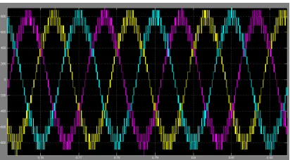
Figure 3 measured phase voltage of MLI output
A. Phase voltage THD
The GA is employed to minimize the objective function for the whole range of fundamental components. The obtained solutions for optimum switching angles are given by SPWM. The corresponding phase-voltage THD is shown in fig.3 Phase-voltage THD, on its own, is of little interest. For a three-phase load, the line-to-line voltage THD is important, since the triple harmonics, present in the phase voltage, are eliminated from the line voltage.
B. Line-Voltage THD Minimization
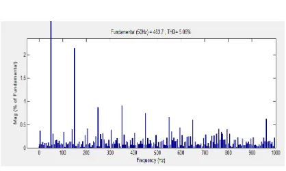
Figure 5 Harmonic spectra analysis of 11 level MLI line voltage
In this approach, the THD minimization algorithm is directly applied to the line-to-line voltage of the inverter. The line-to line voltage waveform is shown in Figure.4. Harmonics spectra analysis is shown in Figure 5
V. CONCLUSION
The disturbances in power electronics equipment are often periodic and rich in higher harmonics. They have been frequencies and are often above the bandwidth of regulators used to control fundamental components. Therefore, the ‘regular’ control can only partially reduce their effects on the distortion of control variables. The cascade multilevel inverter with unequal DC sources is illustrated and the gate triggering pulse is given by the step modulation Genetic algorithms technique. Here the inverter power device circuit used is IGBT device and it has the better switching frequency and gate control compared to all other semiconductor inverter devices such as power MOSFET, SCR, TRIAC etc., This Genetic algorithms control techniques enables us to obtain better selective harmonic reduction characteristics of the output AC voltage under the utilization ratio of different modulation, and achieve optical control of output waveform by different modulation ratio. Finally, we obtained the output AC voltage waveform and their frequency spectrums. Besides that, it realized better multilevel output and achieved desired results.
REFERENCES
[1] C. Cecati, F. Ciancetta, and P. Siano ,“A multilevel inverter for PV systems with fuzzy logic control,” IEEE Trans. Electron., vol. 57, no.12,pp. 4115–4125,2005.
[2]K. El –Naggar , and T.H. Abdelhamid ,“Selective harmonic elimination of new family of multilevel inverters using genetic algorithms,” Energy Converters. Manage., vol. 49, no. 1, pp. 89–95,2008.
[3] F. Khoucha, S.M. Lagoun, K. Marouani, A. Kheloui, and M. El Hachemi Benbouzid, “Hybrid cascaded H-Bridge multilevel-inverter induction motor- drive direct torque control for automotive applications,” IEEE Trans. Ind. Electron., vol. 57, no. 3, pp. 892–899,2010.
[4] S.H. Fathi. M. G. Hosseini Aghdam , A. zahedi, and G.B. Gharehpetia “Optimum regulation of DC-sources in cascaded multi-level inverters, ”COMPEL-Int. J. compute. Math. Elect. Electron. Eng., vol. 28,no.2,pp. 385–395,2009.
[5] L. G. Franquelo, J. Napoles , R.C.P. Guisado , J.I. Leon. , and M.A. Aguirre. , “A flexible selective harmonic mitigation technique to meet grid codes in three-level PWM converters,” IEEE Trans. Ind. Electron., vol. 54, no. 6, pp. 3022–3029,2007.
[6]M.G. Hosseini Aghdam, S.H. Fathi, and G.B. Gharehpetian, “Comparison of OMTHD and OHSW harmonic optimization techniques in multilevel voltage-source inverter with non-equal DC sources,” in Proc. IEEE 7th ICPE, pp. 587–591,2007.
[7]A.K. Kaviani, S.H. Fathi , N. Farokhnia, and A.J. Ardakani, “PSO, an effective tool for harmonics elimination and optimization in multi-level inverters,” in Proc. 4th IEEE ICIEA pp. 2902–2907,2009.
[8]F. Khoucha, S.M. Lagoun. , K. Marouani, A, Kheloui. , and M. El Ha.chemiBenbouzid , “Hybrid cascaded H- multilevel-inverter induction motor-drive direct torque control for automotive applications,” IEEE Trans. Ind. Electron., vol. 57, no. 3, pp. 892–899,2010.
[9] S. kouro, M. Malinowski, K. Gopakumar, J. Franquelo, L. G, Pou, L. G. Rodriguez. M.A. J. B.WU,, M.A. Perez, and J.I. Leon. ,“Recent advances and industrial applications of multilevel converters,” IEEE Trans. Ind. Electron., vol. 57,no. 8, pp. 2553–2580,2010.
[10] M. Saeedifard, R.Iravani , and J. Pou. “Analysis and control of DC-capacitor-voltage-drift phenomenon of a passive front-end five-level converter,” IEEE Trans. Ind. Electron., vol. 54, no. 6, pp. 3255–3266,2007.
[11]Y.shali, and M. K. Fellah , “New approach for the symmetrical multilevel inverters control: Optimal minimization of the total harmonic distortion(OMTHD technique),” in Proc. IEEE ISIE, Ajaccio, France,2004.
[12]Y.sahali, and M. K. Fellah, “Comparison between optimal minimization of total harmonic distortion and harmonic elimination with voltage control candidates for multilevel inverters,” J. Elect. Syst., vol. 1, no. 3, pp. 32–46,2005.
[14]K.Sivakumar,A.Das,R.Ramchand,C.Patel,andK.Gopakumar,“Afive-level inverter scheme for a four-pole induction motor drive by feeding the identical voltage-profile windings from both sides,” IEEE Trans. Ind. Electron., vol. 57, no. 8, pp. 2776–2784,2010 [15]N.Yousefpoor,S.H.Fathi,N.Farokhnia,andS.HSadeghi,“Application of OHSW technique in cascaded multi-level inverter with adjustable DC sources,” pp. 1–6,2009.
BIOGRAPHY
P.Senthilkumar received the B.E. degree in electrical and electronics engineering from PSG College of Technology, Coimbatore. He obtained his M.E. degree in the field of Power System from College of Engineering Gundy (CEG), Anna University. Since 2012, he has been with the Department of Electrical and Computer Engineering in Adama Science and Technology University, Ethiopia and continuing his service as Assistant professor inMizan-Tepi University presently. His current research interests include power electronics, electrical machine drives, active filters, flexible ac transmission systems, high-voltage dc andwireless power transmission. He is a member of IEEE, IET and life-member of Indian Society for Technical Education (ISTE). Along with many International Journal publications, he guided funded projects for UG, PG and Ph.D scholars in the field of transistorized drives,induction heating converters and power flow control drives for power system.