Pavement Distress: A Case Study
Neero Gumsar Sorum1, Thangmuansang Guite2, Nungleppam Martina3
Assistant Professor, Civil Engineering Dept, NERIST, Nirjuli, Arunachal Pradesh, India 1
B. Tech. Student, Civil Engineering Dept, NERIST, Nirjuli, Arunachal Pradesh, India2
B. Tech. Student, Civil Engineering Dept, NERIST, Nirjuli, Arunachal Pradesh, India3
Abstract: Pavement design, the process of developing the most economical combination of pavement layers, mainly deals with the design of material mixtures and thickness of different pavement layers. Even if
highway pavements are well designed and
constructed, they may require proper maintenance; and if not, different distresses like fatigue cracking, bleeding, rutting, potholes etc occur in the pavement which is considered to be complex phenomenon because of several factors involved (like rainfall, traffic etc.).
20 km length of NH-52A was selected, starting from Nirjuli to Itanagar, to carry out survey of pavement distress. 50 important locations of 400 m interval in the highway were selected for the study. In this study, the observation showed that the most commonly found pavement distresses in the highway were pot holes, alligator cracks followed by raveling and edge failure. All the distresses found have values exceeding maximum limits. The most required probable treatments for surveyed distresses are overlay, patching and shoulder improvement. It was also observed that the side drainages were not maintained, cleaned and even absent in some places of the NH-52A.
Keywords: Pavement design, distress,NH-52A, side drainages.
I. INTRODUCTION
Pavement design is the process of developing the most economical combination of pavement layers (in relation to both thickness and type of materials) to suit the soil foundation and the cumulative traffic to be carried during
the design life. Design of pavement structure differs from the design of building, bridges due to the fact that the pavement design till today is based on empirical or semi-empirical approach and there is no rational method of design. Pavement design consists of mainly two parts: (i) Design of the material mixture, to be used in each pavement component layer; (ii) design of pavement structure (design of thickness and type of different component layers). The main factors to be considered in the pavement design are: traffic; climate, road geometry; and position, soil and drainage. Road maintenance is one of the important components of the entire road system. Even if the highways are well designed and constructed, they may require maintenance; the extent of which will depend on several factors including the pavement type.
A brand new pavement at the start of its design life is expected to be one without any “distress” or undesirable features. The more the distress, the shorter the pavement’s life- and at some point, the distresses are so great in intensity (for example, 75% of the wheel path area in project area has cracks) that the pavement is considered to be “failed” or at the end of its design life.
The 90% of road structure in Indian states (including Arunachal Pradesh) are constructed with blacktopping (flexible pavement). Arunachal Pradesh is an integral part of India where the climate varies with elevation. The state receives heavy rainfall of 2,000 to 4,100 millimetres (79 to 160 in) annually, most of it between May and September.
1.1 Types of failures in flexible pavement
As stated above, the localized settlement of any one component layer of the flexible pavement structure could be enough to cause pavement failure. This demands that each one of the layers should be carefully designed and laid. Thus to maintain the stability of the pavement structure as a whole, each layer should be stable within itself and thereby making the total pavement maintain its stability. One of the major challenges facing pavement engineers is how to select the optimal repair strategy for a flexible pavement that is aging and exhibiting distress. This selection process can be relatively straightforward if the cause of the pavement distress is known. Unfortunately, finding the cause of the distress is often
complex.
The different types of distress/failure in flexible pavement are tabulated in Table 1.
Table 1: Types of Distresses in Flexible Pavement No
.
Type of failure
Description
1 Fatigue
(alligator) cracking
Series of interconnected cracks caused by fatigue failure under repeated traffic loading
2 Bleeding Film of asphalt binder on the pavement surface
3 Block
cracking
Interconnected cracks that divide the pavement up into rectangular blocks (approx. 0.1 m2 to 9 m2)
4 Corrugati
on and shoving
A form of plastic movement typifiedby ripples(corrugation) or an abrupt wave (shoving) across the pavement surface
5 Depressio
n
Localized pavement surface areas with slightly lower elevations than the surrounding pavement
6 Joint
reflection cracking
Cracks in a flexible overlay of a rigid pavement which occur directly over the underlying rigid pavement joints
7 Longitudi
nal cracking
Cracks parallel to the pavement's centerline or laydown direction (a type of fatigue cracking)
8 Patching An area of pavement that has
been replaced with new material to repair the existing pavement
9 Polished
aggregate
Areas where the portion of aggregate extending above the asphalt binder is either very small or there are no rough or angular aggregate particles
10 Potholes Small, bowl-shaped depressions
in the pavement surface that penetrate all the way through the HMA layer down to the base course
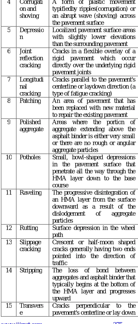
11 Raveling The progressive disintegration of an HMA layer from the surface downward as a result of the
dislodgement of aggregate
particles
12 Rutting Surface depression in the wheel path
13 Slippage cracking
Crescent or half-moon shaped cracks generally having two ends pointed into the direction of traffic
14 Stripping The loss of bond between
aggregates and asphalt binder that typically begins at the bottom of the HMA layer and progresses upward
15 Transvers
e
(thermal) cracking
direction is usually a type of thermal cracking
16 Water
bleeding and pumping
Water bleeding occurs when water seeps out of joints or cracks or through an excessively porous HMA layer. Pumping occurs when water and fine material is ejected from underlying layers through cracks in the HMA layer under moving loads
II. OBJECTIVES OF THE STUDY
The main objective of the present study was to carry out a survey on pavement distresses present in National Highway of Arunachal Pradesh (NH-52A), India. The specific objectives of this study were:
1. To identify the different locations of pavement distress in the highway.
2. The frequency of pavement distress
present on this highway stretch.
3. To study possible causes of these distresses and at meantime suggesting remedies and solutions for these distresses.
4. To assess the performance of the Highway.
III. SCOPE OF THE STUDY
Site observations of flexible pavement distress in various countries indicate frequent occurrence of longitudinal (top-down) cracking from the top surface layer. However, due to the complexity of tire/pavement interaction resulting from tire geometry and loading conditions, the accurate and fully representative distribution of surface stresses remains partly unknown. The study of flexible pavement distress is advantageous for the highway engineers because of the following reasons:-
1. It gives us the most accurate reason for the pavement distress/failure which makes the repairing work easy.
2. The knowledge about pavement distress enables us able to make more efficient and high performance pavement.
3. Hence, high performance pavement ensures efficient traffic flow and safety to the passengers.
4. Moreover, the study of pavement distress in an area helps in the improvement in design of the pavement, which may be so more effective in the area.
IV. LITERATURE REVIEW
Markwick and Starks (1941) measured the contact stresses between light-weight truck tires and pavement. The inflation pressure was 0.28 - 0.35 MPa (40 to 50 psi). The authors concluded that the local contact normal stresses induced by a pneumatic tire were approximately 1.5 times higher than the inflation pressure. The normal stresses appear to be independent of truck speed. Shear stresses were directed inwards. Under a solid tire, the shear stresses were directed outwards.
Seitz and Hussmann (1971) performed experimental studies on a radial-ply passenger car tire without profile. The authors observed inward shear stresses along the contact. The authors concluded that these stresses are due to sidewall bending (pneumatic effect), and that the compression of tread rubber (Poisson's effect) only reduces the magnitude of contact shear stresses due to bending but not their direction.
Lippmann (1985) measured the distribution of stresses between the tread of the passenger radial-ply tire and pavement. The author noticed that bulging of the tire results in inward shear stresses at the edge of the tire.
Gerritsen et al. (1987) conducted a field study in the Netherlands on the occurrence of surface cracking in asphalt pavements, and on the potential causes of surface cracking. Static indirect tensile tests were performed on core samples collected; they showed that the asphalt concrete outside of the wheel paths tended to have low strength characteristics at low temperatures.
observed 3 to 5 years after construction of the road containing a slow lane and a fast lane. The longitudinal cracks were located on the centerline side of the slow lane. It also observed that the appearance of cracks fluctuated with the seasons.
Sebaaly and Tabatabaee (1989) tested radial-ply, bias-ply and wide-base radial-ply single tires using different levels of inflation pressures from 0.52 to 0.76 MPa (75 to 110 psi). The authors reported that the contact pressure distributions were non-uniform, with maximum contact pressures of 1.75 times the inflation pressures. The maximum contact pressures were obtained along the center tread for all three tires, and the minimum contact pressures were obtained along the outer tread.
Huhtala et al. (1989) measured contact pressure for two twin tires, and three twin tires. Tire pressure was varied from 0.48 to 1.08 MPa (70 to 157 psi). For passenger car tires, the contact pressures reached maximum at the edge. On the other hand, for truck tires, the contact pressures attained a maximum at the tire’s center.
Matsuno and Nishizawa (1992) examined longitudinal surface cracking in asphalt pavements in Japan. Visual observations indicated that the cracking appeared 1 to 5 years after the road’s construction typically occurred in the passing lane. It was also observed that the cracks were within or very close to the wheel paths. In addition, cracks did not appear in shadowed areas such as near an overpass bridge.
Matsuno and Nishizawa (1992) performed axisymmetric elastic finite element analysis with uniform normal contact stress representing the entire tire contact pressure. The Poisson's ratio of 0.35 was kept constant. From the analysis, the authors concluded that the strains under the tire are mainly compressive in the vertical direction, and high lateral tensile strains at the tire edge were sufficient to cause cracking.
Perdomo and Nokes (1993) used the computer program CIRCLY to examine the response of a flexible pavement system due to different loading. Two types of loading were considered: non-uniform normal tractions only and uniform normal tractions accompanied by
non-uniform inward shear tractions. The authors concluded that when inward shear tractions were considered in the analysis, the maximum tensile strains occur on the surface of the pavement at the edges of the tires.
Jacobs (1995) analyzed the stresses in a pavement structure consisting of three layers, with constant thickness for each layer, one Poisson's ratio for all layers, the same elastic modulus for base and subgrade layers, and three different elastic moduli for the AC layer. He concluded that the normal stresses at the bottom of the asphalt concrete layer were not affected by the tangential stress on the surface. The tensile stresses at the edge of the loaded area can be much higher than the tensile stresses at the bottom of the asphalt concrete layer.
Collop and Cebon (1995) examined the potential of longitudinal surface fatigue cracking in asphalt pavements using different analytic and numerical solutions. From 2D plane strain elastic half-space solution, the author concluded that there is singularity in surface stresses at both ends of the contact if a discontinuity in shear tractions is assumed. The authors concluded that shear tractions between the tire and the pavement induce high local tension around the edge of the contact patch, which may lead to surface longitudinal cracks that propagate by thermal fatigue.
V. METHODOLOGY/FIELD INVESTIGATION
National Highway 52A (NH-52A) starts from
Banderdewa, Arunachal Pradesh and ends at Gohpur, Assam. The highway is 57 km long, of which 15 km is in Assam and 42 km in Arunachal Pradesh. On October 17th, 2007, Wednesday, the union ministry of road transport and highways has transferred the Hollongi to Banderdewa portion of NH-52A from the Border Roads Organization (BRO) to Arunachal Pradesh Public Works Department (PWD). It is under the Arunachal PWD till present.
measured. The total studies was divided into 3 days; in each day, approx. of 7 km of survey was carried out, starting from Nirjuli. The survey of pavement distress was done at 50 important locations, after dividing the selected length (20 km) of the highway into 400 m stretch interval.Some of the photographs of the study done on NH-52A are shown in figures 1-9.
Figure 1. Pot holes and longitudinal cracks
Figure 2. Deep pot hole consuming almost half of wheel radius (175mm deep)
Figure 3.Raveling
Figure 5. Big pot hole filled with drainage water and raveled aggregates (Naharlagun)
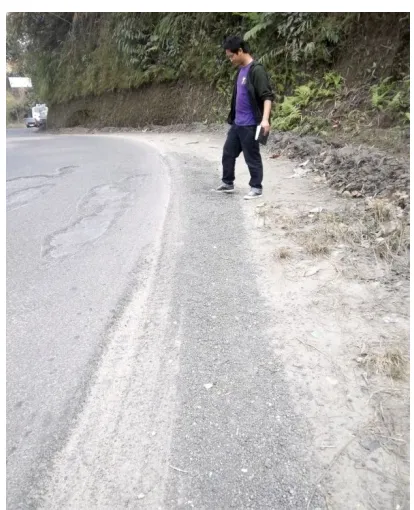
Figure 6. Total edge raveling failure- can cause accidents in case a vehicle take over from extreme corner as it’s
located on S-curve.
Figure 7. Total failure of pavement in Nirjuli
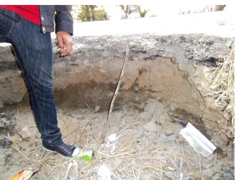
Figure 9. Failure on road side caused by subgrade failure
VI. RESULTS AND DISCUSSIONS
The basic reason for pavement distresses along the Highway and flexible pavement in general is a resultant ofpoor implementation of mix design and poor workmanship followed by lack of timely maintenance. Details of the distresses found in NH-52A starting from Nirjuli – Itanagar are tabulated in Table 2.
Table 2: Details of the distresses found in NH-52A
No .
Location Type Length
(mm)
Depth (mm)
1 Bage Tinali Pothole 2000 130
2 Bage Tinali Pothole 1330 127
Stripping 540
3 Bage Tinali
Tee-Junction
Pothole 3990 117
4 Bage Tinali
near Jully furniture
Pothole 3002 119
Stripping 490
5 Turning at Bage
Tinali near Maruti workshop
Pothole 2503 112
Stripping 620 Edge
raveling
2000
6 Techno Service Pothole 2600 129
near SAIL warehouse
Alligator cracking
1005
7 Near Techno
Service
Longitud inal cracking
12850
8 35m from
Techno towards Itanagar
Pothole 1126 70
9 Lekhi Village
near LN Car Wash Centre
Pothole 2348 190
Subgrade failure
1500 1000
10 Govt. Middle
School
Pavemen t failure
45300
11 Near Tarh
Driving School
Longitud inal Failure
7000 across the road
12 Near way to
Yupia
Alligator Cracks
1875
13 Near way to
Yupia
Pothole 2351 210
14 NIT junction,
Yupia
Pothole Longit
udinal 290
15 PWD office,
Papu Nalah
Pothole 1452 124
16 S-curve near Sango Restaurant
Pothole Across
7100 wide road
136
17 S curve near car wash
Pothole 2341 300
18 Raj Bhawan,
Itanagar
Pavemen t failure
14280
19 Best Baker, Pothole
filled
Itanagar with roadside water
20 Bank Tinali Pothole 2453 198
21 Near Petrol
Pump, Itanagar
Longitud inal cracking
2000
Interestingly,It was observed that the side drainages of the NH-52A were not maintained, cleaned and even absent in some places (for example near Shiv Mandhir location, 6 km away from Naharlagun).
The most commonly found pavement distresses were pot holes, alligator cracks followed by raveling and edge failure.The relative scale for measuring the severity of pot holes with respect to depth is:Low < 25mm deep; Moderate 25mm to 50mm, High >50mm deep. The average depth of pot holes found in NH-52A is 90-100 mm deep and the deepest pot hole found being 300 mm.
It was observed that bleeding was almost absent along this highway which may indicate that overall use of binder content is very much below the required amount.Stripping phenomenon due to heavy rainfall and implementation of poor mix design of bituminous mix may also be the factors for this.It was also observed that most of the cracks were top-down cracks starting with the bitumen-aggregate binding failure which indicates poor mix design.Poor/absent drainage also caused stripping in some spots causing deep holes and large edge cracks.
The possible causes and probable treatments of the surveyed distresses are discussed below.
1. Fatigue (alligator) cracking: No
.
Possible Causes Probable Treatment
1 Inadequate
pavement thickness
Strengthen the pavement or reconstruction
2 Low modulus
base
Strengthen the base or reconstruction
3 Brittle base Base recycling or
reconstruction
4 Poor base
drainage
Improve the drainage and reconstruct
5 Brittle wearing course
Replace or treat wearing course
2. Edge cracking: No
.
Possible Causes Probable Treatment
1 Inadequate pavement
width
Widen the pavement
2 Alignment which
encourages drivers to travel on the pavement edge.
Pavement widening and realignment
3 Inadequate edge
support
Shoulder strengthening
4 Seepage and heavy
rainfall
Proper and efficient drainage
3. Longitudinal cracking:
No .
Possible Causes Probable Treatment
1 Reflection of
shrinkage cracks
Cut and patch
2 Poorly Constructed
paving lane in bituminous surfacing
Replace bituminous surfacing
3 Displacement of joints at pavement widening
Reconstruction of joints
4 Differential settlement between cut and fill
Crushed aggregate overlay or reconstruction of joints
4. Potholes:
No .
Possible Causes Probable Treatment
1 Loss of surface course due to heavy rainfall
Patching
2 Moisture entry to base course through a cracked pavement
surface
3 Load associated
disintegration of base
Base reconstruction
5. Raveling:
No .
Possible Causes Probable
Treatment
1 Insufficient bitumen
content
Thin bituminous overlay
2 Poor adhesion of bitumen
binder to aggregate particles due to wet aggregate
Thin bituminous overlay
3 Inadequate compaction or
construction during wet weather
Thin bituminous overlay
4 Deterioration of binder and/or aggregate Thin bituminous overlay 6. Rutting: No .
Possible Causes Probable Treatment
1 Inadequate pavement
thickness
Strengthening overlay or reconstruction
2 Inadequate compaction
of structural layers
Reconstruction
3 Unstable bituminous
mixes
Replace or recycle bituminous surfacing or use the stiffer mix
4 Unstable shoulder
material which does not provide adequate lateral support
Shoulder
improvement and overlay rutted area with bituminous surfacing
5 Overstressed sub-grade
which deforms permanently
Reconstruction
6 Unstable granular bases
or sub bases
Base or sub base strengthening 7. Transverse (thermal) cracking:
No .
Possible Causes Probable Treatment
1 Reflection of
shrinkage cracks
Cut and patch
2 Construction joint in bituminous surfacing
Crack sealant
3 Structural failure of Portland Cement
Reconstruction of base
4 Shrinkage crack
bituminous surfacing
Seal cracks or replace bituminous surfacing 5 Reflection of joints in
the underlying base
Crushed aggregate overlay or reconstruction of joints
8. Block cracking:
No .
Possible Causes Probable Treatment
1 Joints in underlying layer
Crushed aggregate overlay
2 Shrinkage and fatigue
of underlying cemented materials
Replace underlying cemented materials
3 Shrinkage cracks (due
to bitumenhardening) in bituminous surfacing
Seal cracks or replace bituminous surfacing
4 Fatigue cracks in embrittled bituminous wearing course
Cut and patch or crushed aggregate overlay
9. Polished aggregates:
No .
Possible Causes Probable Treatment
1 Inadequate resistance to polishing of surface aggregates particularly in areas of heavy traffic movements or where high stresses are developed between surface and tyres
The bituminous overlay of use of stiffer mix
2 Use of naturally smooth
uncrushed aggregates
Thin bituminous overlay
No .
Possible Causes Probable
Treatment 1 Inadequate cleaning or
inadequate tack cot before placement of upper layers
Mill off and re-lay upper re-layers
2 Seepage of water through
asphalt, especially in cracks, to break the bond between surface and lower layers.
Replace wearing course or thin bituminous overlay
3 Weak, loose layer
immediately
Reconstruction of weak layers
VII. CONCLUSIONS
The side drainages are not maintained, cleaned and even absent in some places of the NH-52A.
The average depth of pot holes found in NH-52A is 90-100 mm deep, exceeding the limits. And the deepest pot hole found being 300 mm.
The bleeding distress was not found along this highway.
All distresses found in the highway were exceeding their maximum limits.
The interval of the pavement distresses found is too frequent and well exceeded the standard limits.
The most required probable treatments for surveyed distresses are overlay, patching and shoulder improvement.
RECOMMENDATION
Since the frequency and interval of the pavement distresses is too much and well exceeded the standard limits, immediate repair and maintenance is required-either Overlay or Resurfacing.Simultaneously mix design of selected mix should be analyzed at the laboratory, if possible, before implementation in the field. All the materials should be up to the standard recommended by the MoRTH.
ACKNOWLEDGEMENT
The authors wish to thank the Department of Civil Engineering, NERIST, and all those involved directly or indirectly on producing this paper.
REFERENCES
[1] Bensalem, A., Brown, A.J., Nunn, M.E., Merrill, D.B., and Lloyd, W.G.,(2000), “Finite Element Modeling of Fully Flexible Pavement: Surface Cracking and Wheel Interaction”, Proceedings of the 2nd International Symposium on 3D Finite Element for Pavement Analysis, Design, and Research, pp. 103-113.
[2] Collop, A., and Cebon, D.,(1995), “A Theoretical Analysis of Fatigue Cracking in Flexible Pavements”, Proceedings of the Institution of Mechanical Engineers. Part C, Vol-209, No. 5, pp. 345-361.
[3] Dauzats, M., and Rampal, A.,(1987), “Mechanism of Surface Cracking in Wearing Courses”, Proceedings of the 6th International Conference on Structural Design of Asphalt Pavements, pp. 232-247.
[4] Georgopoulos,A., Loizos, A., and Flouda, A.,(1995), “Digital image processing as a tool for pavement distress evaluation”, ISPRS Journal of Photogrammetry and Remote Sensing, Elsevier Science B.V.
[5] Gerritsen, A., Gurp, C.V, Van der Heide, J., Molenaar, A. and Pronk, A.,(1987), “Prediction and Prevention of Surface Cracking in Asphaltic Pavements”, Proceedings of the 6th International Conference on Structural Design of Asphalt Pavements, pp. 378-392.
[6] Huhtala, M., Pihlajamäki, J.,and Pienimäki, M.,(1989), “Effects of Tires and Tire Pressure on Road Pavements”, Transportation Research Record 1227, Transportation Research Board (TRB), National Research Council (Washington D.C.), pp. 107-114.
[7] Indian Roads Congress,(2001), “Guidelines for the design of Flexible Pavements”, Jamnagar House, Shahjahan Road, New Delhi-110 001, India.
[8] Indian Road Congress,(2001),“Specification for Road and Bridge Works”, 4th Revision, Ministry of Road Transport and Highways, Government of India, New Delhi-110001.
[9] Jacobs,M.M.J., (1995), “Crack Growth in Asphaltic Mixes”, Ph.D. thesis, Delft University of Technology, The Netherlands.
[10] Khanna, S.K., and Justo, C.E.G.,(2001) “Highway Engineering”, Published by Nem Chand & Bros., Civil lines, Roorkee 247667, India.
[11] Kumar, R.S., (2011), “Textbook of Highway Engineering”, Published by Universities Press Private Limited, Himayatnagar, Hyderabad 500029, India.
[13] Markwick, A.H.D., and Starks, J.H.,(1941), “Stresses between Tire and Road”, Journal of the Institution of Civil Engineers, Vol- 16, pp. 309-325.
[14] Matsuno, and Nishizawa, T., (1992),“Mechanism of Longitudinal Surface Cracking in Asphalt Pavement”,Proceedings of 7th International Conference on Asphalt Pavements, Vol-2, pp. 277-291.
[15] Myers,L.A., Roque, R., and Ruth, B.,(1998), “Mechanisms of Surface-Initiated Longitudinal Wheel Path Cracks in High-Type Bituminous Pavements”, Journal of the Asphalt Paving Technologists, Vol-67, pp. 401-432.
[16] O’Flaherty, C.A.,(2001), “Highways- The Location, Design, Construction & Maintenance of Pavements”,Butterworth- Heinemann, Woburn, MA.
[17] Perdomo, D., and Nokes, B.,(1993), “Theoretical Analysis of the Effects of Wide-Base Tires on Flexible Pavement Using CIRCLY”, Transportation Research Record 1388, Transportation Research Board (TRB), (Washington D.C.), 108-119.
[18] Sebaaly, P., and Tabatabaee, N.,(1989),”Effects of Tire Pressure and Type on Response of Flexible Pavement”. Transportation Research Record 1227, Transportation Research Board (TRB), National Research Council (Washington D.C.), pp.115-127.
[19] Seitz, N., and Hussmann, A.W.,(1971), “Forces and Displacements in Contact Area of Free Rolling Tires”, Society of Automotive Engineers, 710626, Society of Automotive Engineers, Inc., pp.1-7.