18th International Conference on Structural Mechanics in Reactor Technology (SMiRT 18) Beijing, China, August 7-12, 2005 SMiRT18-A01-7
IRRADIATION BEHAVIOUR AND STRUCTURAL ANALYSIS OF
HTR/VHTR GRAPHITE CORE COMPONENTS
B.J.Marsden
∗, Siu-Lun Fok, Haiyan Li
Nuclear Graphite Research Group
School of Mechanical, Aerospace and Civil Engineering
The University of Manchester
Manchester M60 1QD, U.K.
Tel: 44-(0)-161-275 4399
Fax: 44-(0)-161-275 4328
[email protected]
ABSTRACT
Based on the HTR/VHTR design concept, the microstructure of nuclear graphite available for HTR/VHTR reactor is reviewed. The relationship between the irradiation damage mechanism to graphite crystal and the irradiation behaviour of polycrystalline graphite is analyzed under the condition of interest to HTR/VHTR. New methods and tools are being developed for stress analysis and failure prediction of nuclear graphite components in HTR/VHTR.
Keywords:HTR/VHTR, graphite, irradiation, strength, failure
1 INTRODUCTION
There are two main high-temperature gas cooled reactor (HTR) design concepts: a pebble-bed concept (as used in AVR, THTR, HTR-10 and PBMR) and a prismatic concept (as used in Dragon, Peach Bottom, Fort St. Vrain, HTTR and GT-MHR) [1,2]. In all these designs, the graphite is employed as a moderator and/or major structural components which provide channels for the fuel and coolant gas, and control and safety shut off devices, as well as providing thermal and neutron reflection and shielding. In addition, graphite components may act as a heat sink or conduction path during reactor trips and transients.
During HTR operation the dimensions and material properties of graphite components are changed by fast neutron irradiation as a function of irradiation dose (fluence) and temperature. The physical changes to the graphite properties that are of concern to the HTR designers and operators are: dimensional change, coefficient of thermal expansion, Young’s modulus, strength, thermal conductivity and irradiation creep. Young’s modulus, strength, thermal conductivity and creep are all modified by weight loss. There is also evidence that dimensional change is modified by weight loss, however in an HTR the level of weight loss is unlikely to be significant enough to affect dimensional change.
bypass (or blockage) and control rod entry restriction.
In HTR designs some graphite components are replaced at regular intervals along with the fuel, such as the prism fuel blocks. Others can easily be changed part way through reactor life, such as the replaceable reflector in the prism type design. However, other graphite components such as the permanent reflector may be more difficult to replace and therefore may have to retain their integrity for the whole life of the reactor. Therefore, it is important that the reactor designer understands how the nuclear graphite will behave throughout its life in reactor, through graphite component stress analysis and failure predictions for the graphite core components.
The irradiation behaviour of graphite is strongly dependent on its virgin microstructure, which is determined by the manufacturing route. Fortunately there are available irradiation data on many obsolete types of graphite of known microstructures. There is also a fairly well, but to completely, developed physical understanding of the process of irradiation damage in graphite.
Reliable structural analysis and failure prediction tools and methods are the subject of ongoing studies. Based on the knowledge of irradiation behaviour, the finite element method has been used for structural calculations and failure prediction bt applying user-defined material and user-defined element to nuclear graphite behaviour.
This paper discusses the irradiation behaviour of nuclear graphite available for HTR/VHTR reactors as well as the structural analysis and failure prediction methods for graphite core components. All doses in this paper are given as Equivalent DIDO Nickel Dose (EDND).
2 NUCLEAR GRAPHITE IN HTR/VHTR REACTORS 2.1 Polycrystalline graphite microstructure
Nuclear graphites are polycrystalline in structure being manufactured from moulded and extruded petroleum cokes and a suitable binder. The final polycrystalline microstructure is determined by the structure of the coke and the binder phase and also by the manufacture process. The manufacture process leads to a product with approximately 20% porosity either as gas evolution pores in the binder or within the crystallite longitudinal cracks of various widths often referred to as Mrozowski cracks.
At the crystallite level the graphite has strong hexagonal basal planes with much weaker bonding between the planes. Due to the large difference in the coefficient of thermal expansion in the two crystallographic directions, on cooling from the graphitization temperature ~3000oC large numbers
of ‘‘Mrozowski’’ cracks can appear in the ‘c’ direction. It is this “cracked” structure that gives graphite good thermal shock resistance, allowing large crystal expansion in the ‘c’ direction without leading to inter-crystalline cracking. These cracks also provide accommodation spaces that can be taken up by irradiation-induced crystal growth and play an important role in determining component property changes in reactor.
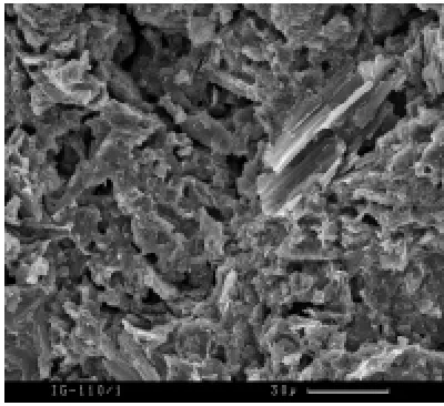
Beyond this scale, the crystallite structures are joined together and follow the general shape of the coke particle. There are many larger cracks and fissures which also tend to follow the coke particle shape. Examples of this are illustrated in Figure 1. It can be seen that the general alignments of the ‘a’ axis is with the “flow” of the coke particle with the ‘c’ axis perpendicular to this direction. It can also be seen that the shape, size, distribution and orientation of the coke particles will strongly influence the material property of the final graphite component.
Some modern types of graphite, such as IG-110, are manufactured from finely ground coke particles, which can produce semi-isotropic properties. The coke particles are usually bound together using a pitch binder. The binder itself will probably be mixed with a “flour” consisting of finely ground coke and possibly scrap graphite. The baked structure may have also have been impregnated once or twice to increase the overall density. The binder structure can be clearly distinguished in Figure 1. Features that are of interest are the randomly ordered, well-structured, small particles and the large gas evolution pores.
2.2 Irradiation damage to the graphite crystal
Fast neutron energies in a thermal reactor range from less than 1eV to ~10MeV with a mean energy of ~2MeV. Radiation damage occurs in graphite due to carbon
atoms being displaced from the crystal lattice.
Simmons[3] used theory based on work by Bohr to establish the nature of damage throughout the graphite lattice. He showed that at high energies the probability is greater and that the energy transfer from a primary knock-on is only a small fraction of the initial energy of the moving atom. At lower energies there is a tendency towards an equal distribution between the moving and struck atoms. Simmons also showed that for the primary knock-ons, at high energies, the mean distance between displacement collisions was large compared with the graphite lattice inter-atomic spacing. The secondary knock-on energy is less than 500eV; at this energy, the mean distance between collisions becomes comparable to the lattice spacing. From the work of Simmons it is therefore predicted that a primary knock-on would produce separate groups of secondary knock-ons as illustrated in Figure 2.
Displaced carbon atoms may recombine into vacant positions within the graphite crystal lattice become lost to the boundaries, or combine with other atoms to form interstitial loops in the relatively large inter-layer spacing. Likewise vacant sites may eventually join together to form small vacancy loops which may eventually lead to collapse of the basal planes.
Fig. 2 Displacement cascade and the formation
of interstitial loops
2.3 Irradiation behaviour of graphite crystal
Irradiation damage changes the material properties of the graphite crystal: such as dimensional changes, coefficient of thermal expansion, mechanical properties and thermal conductivity. To understand the irradiation behaviour of nuclear polycrystalline graphite, it is essential to understand the behaviour of the graphite crystallites that are the main structural component of nuclear graphite.
polycrystalline graphite that occurs between 800 and 1100oC.
(a) (b)
Fig. 3 Crystal dimensional change
Coefficient of Thermal Expansion (CTE) The CTE of a graphite crystal is much larger in the ‘c’ direction than in the ‘a’ direction. When subjected to fast neutron irradiation at relatively low temperatures, below ~250oC, the CTE in the ‘c’ direction reduces at a dose of ~ 5 x 10²⁰ n/cm2, whilst at a similar dose the CTE in the ‘a’ direction increases from a small negative value to a small positive value. This behaviour appears to be associated with the large growth in the ‘c’ axis at these lower irradiation temperatures. Fortunately this complication is not of interest for HTR technology.
At higher irradiation temperatures, above ~300oC, the CTE of the crystallite in both the ‘a’ and ‘c’ appears to be independent of irradiation dose, remaining at the unirradiated value, however data to confirm this finding only exists for ~450 and 600oC.
Mechanical properties The mechanical properties of the crystallite were studied by Kelly[5]. As would be expected by consideration of the structure of the crystal lattice, the modulus parallel to the basal plane (C11) is much larger
than that perpendicular to the basal plane (C33). The shear modulus parallel to the basal plane (C2) is relatively low,
but the shear modulus for a single layer (C1) is higher. With irradiation C33 tends to slightly reduce whilst C2
significantly increases. Both these elastic moduli are associated with inter-layer forces.
Thermal conductivity The changes to thermal conductivity with irradiation are large and are dependent on the irradiation temperature. The graphite crystal possesses two principal conductivities, Kc and Ka, measured parallel and perpendicular to the hexagonal axis. Measurements[5] have shown that Ka>>Kc.
In the temperature ranges of interest in HTRs the thermal conductivity of a graphite crystal is dominated by lattice vibrations[6]. At high temperatures, the conductivity of the crystal both perpendicular and parallel to the basal plane is controlled by phonon scattering. Phonon scattering is increased by increasing temperature. In a less than perfect crystal, scattering will occur at defects and the effect of irradiation will increase the number of defects within the lattice, thus reducing the thermal conductivity.
2.4 Polycrystalline graphite irradiation behaviour
The changes in material properties in a polycrystalline graphite are governed by the irradiation-induced changes in the crystallites and the interaction of the crystallites with the porosity within the graphite.
behaviour can be explained by reference to the micro cracks. These cracks take up the ‘c’ crystallite expansion, thus up to turn-around the ‘a’ shrinkage dominates the irradiation behaviour. However when all of the accommodation has been taken up the ‘c’ axis expansion starts to become dominant and the polycrystalline graphite turns-around and starts to swell. This expansion can only continue to a certain point as straining of the polycrystalline structure will eventually lead to degradation of the structure and loss of strength.
Gilscarbon Dimensional change
-4.00 -3.00 -2.00 -1.00 0.00 1.00 2.00 3.00 4.00 5.00 6.00
0 5E+21 1E+22 1.5E+22 2E+22
Dose n/cm2
EDND
∆
L/
L %
430o
C 600o
C 1240oC
1430 o
C
940oC
GCMB and IM1-24 data
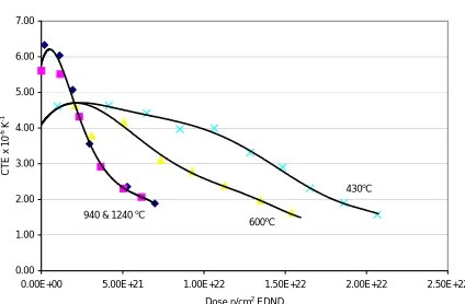
Gilsocarbon Coefficient of Thermal Expansion
0.00 1.00 2.00 3.00 4.00 5.00 6.00 7.00
0.00E+00 5.00E+21 1.00E+22 1.50E+22 2.00E+22 2.50E+22
Dose n/cm2
EDND
CTE x 10
-6 K
-1
600oC
430oC
940 & 1240 oC
Fig. 4 Dimensional change in Gilsocarbon Fig. 5 Irradiation-induced changes in the
g
raphite CTE in Gilsocarbon graphite
Figures 4 shows the dimensional change curves for Gilsocarbon graphite irradiated over the temperature range 430-1430oC. These curves are typical for modern graphite, the important features that should be noted that:
The large reduction in the dose to turn-around between 600 and ~900°C.
The marked change in behaviour of the curves for graphite irradiated above 900°C. The rapid swelling of graphite after turn-around at the higher temperatures.
Figures 5 shows the irradiation-induced change to the CTE between 430-1240oC. These curves are typical for modern graphite, the important features that should be noted that:
The initial increase in CTE attributed to the closure of the Mrozowski cracks. The fall of CTE with dose after this initial peak
The levelling out of CTE at very high dose.
It can be seen that the peak in CTE and dimensional change turn-around do not coincide and there is some evidence that these features are related to different aspects of porosity (cracks sizes) within the graphite structure.
Young’s Modulus The stress-strain behaviour of polycrystalline graphite is highly non-linear, both in tension and compression, with the stress to strain relationship increasing with increasing cyclic stress. The elastic modulus of graphite increases with temperature up to ~2000oC before decreasing to zero at ∼3000oC. Over the temperature range of interest in HTR designs, the increase is small, but the designer may want to take it into account.
Figure 6 shows the change in Young’s modulus with irradiation dose in Gilsocarbon graphite. Again this behaviour is typical of modern nuclear graphite. Features to note are:
The rapid increase in modulus contributed to pinning. The following relatively slow increase
The second increase in modulus due to tightening of the structure The final fall off in modulus at very high dose
early in reactor life. Unfortunately, the data and theory for irradiation creep are limited and contradictory.
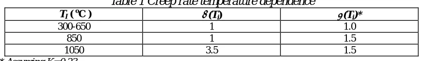
Irradiation creep strain in graphite in the UK is usually described by the Brocklehurst-Kelly model [7], where for both positive (tensile) and negative (compressive) creep by a simple linear visco-elastic model which includes a primary and secondary creep term:
ε
α
( )
σ
γβ
( )
σγ
γi c c
i
c
T
E
K
e
E
T
o+
−
=
1
− (1)where σ is the applied stress, Ec is the creep modulus[8], γ is the neutron dose, α(Ti) and β(Ti) are irradiation
temperature and dose dependent factors and K and γo are constants.
It can be seen from the datain Table 1 [7] that in the HTR temperature range both α(Ti) and β(Ti) are a function of
temperature. This behaviour is also confirmed by the Russian and US creep laws [9].
G ilsocarbon Young's M odulus
-1.00 -0.50 0.0 0 0.5 0 1.0 0 1.5 0 2.0 0 2.5 0 3.0 0 3.5 0
0.00E+00 5.00E+21 1.00E+2 2 1.50E+22 2.00E+22 2.50E+2 2
D ose n/cm2ED N D
E/ Eo -1
430oC
600o
C
1240oC
940o
C
1430o
C
Fig. 6 Irradiation-induced changes to Young’s Fig. 7 The relationship between the CTE
modulus in Gilsocarbon graphite and creep strain
Table 1 Creep rate temperature dependence
TI(oC ) α(Ti) β(Ti)*
300-650 1 1.0
850 1 1.5 1050 3.5 1.5 * Assuming K=0.23
A Poisson’s ratio of 0.5 is usually associated with creep in metals. However, data obtained in the many irradiation creep experiments on graphite indicate that a value of Poisson’s ratio for creep the same as that for elastic ~0.2 is more appropriate [7].
Data for the relationship between irradiation creep strain and the coefficient of thermal expansion is given in several publications including Kelly and Burchell [10]. Figure 7 gives the small amount of information on the relationship of creep strain to CTE derived from various experiments.
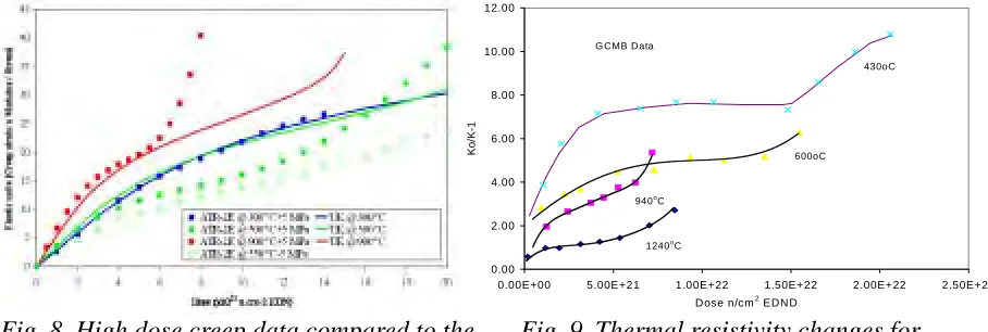
In the late 1970s high dose creep data became available for both German and US graphites. This data was for irradiation at and beyond volumetric turn around. This high dose data gave some unexpected results shown in Figure 8:
At high dose there was a difference between the creep rate in tension and compression. There was a significant reduction in creep rate at “turn around”
There was a significant increase in creep rate as the volumetric expansion returned to zero
Thermal Conductivity The thermal conductivity of polycrystalline graphite is a function of dose and temperature. In graphite technology, it is usual to work in thermal resistance 1/K (K is thermal conductivity). Figure 9 shows the thermal resistivity changes of Gilsocarbon graphite.
0.00 2.00 4.00 6.00 8.00 10.00 12.00
0.00E+00 5.00E+21 1.00E+22 1.50E+22 2.00E+22 2.50E+22
Dose n/cm2 EDND
Ko
/K-1
G CMB Data
430oC
600oC
940oC
1240oC
Fig. 8 High dose creep data compared to the Fig. 9 Thermal resistivity changes for
U
K creep rule Gilsocarbon graphite
3 STRESS ANALYSIS OF GRAPHITE CORE COMPONENTS
The finite element (FE) method is widely used to complete structural analysis in a variety of areas, especially for complex structures. In order to take stress analysis of nuclear graphite core components using FE method, the irradiation behaviour of graphite must be taken into account. Based on the commercial finite element code ABAQUS, the user material subroutine UMAT has been developed to model the graphite constitutive law under irradiation and high temperature [13].
The constitutive law defined in UMAT is:
idc ith dc th sc pc e
total
ε
ε
ε
ε
ε
ε
ε
ε
=
+
+
+
+
+
+
(2) ande
ε
σ
=
D
⋅
(3) where , , , , , , and are the total strain, elastic strain, primary creep strain, secondary creep strain, thermal strain, dimensional change strain, interaction thermal strain due creep and interaction dimensional change strain due to creep respectively.total
ε
ε
eε
pcε
scε
thε
dcε
ithε
idcσ
is the stress and D is the elastic matrix.In each increment of the numerical solution, (2) and (3) are given in an incremental form as: idc ith
dc th
sc pc e
total
ε
ε
ε
ε
ε
ε
ε
ε
=
∆
+
∆
+
∆
+
∆
+
∆
+
∆
+
∆
∆
(4)and
e
e
ε
ε
σ
=
⋅
∆
+
∆
⋅
∆
D
D
(5) where the creep strain increments∆
and , dimensional change increment∆
and the two interaction items∆
and are calculated according to the irradiation-induced property changes as described in section 2.4. But the irradiation dose, temperature, weight loss and attack rate need to be provided as field variables for the calculation.pc
ε
∆
ε
scε
dcith
4 FAILURE PREDICTION OF GRAPHITE COMPONENTS
Graphite is a brittle material and the failure strength depends on component size, geometry and mode of loading. For specimens of a similar size, graphite is stronger in compression than bending and stronger in bending than tension. In regions of high stress concentration components have a much higher failure stress than would be predicted from small-scale testing. Thus it is difficult to predict the failure of a graphite component from small specimen tests even without considering the complexity of irradiation damage. In the UK, it has been the practice to carry out failure tests on full size components in all of the predicted loading modes. These tests, along with finite element assessments are then used to predict the failure stress at the critical load. As failure is a statistical process it is necessary to carry out enough tests to determine the mean and standard deviation for use in probabilistic assessments. Having obtained these data for the unirradiated components, the failure stresses are then modified for the effect of fast neutron irradiation and thermal or radiolytic oxidation using the methods described below. The development of a more rigorous and flexible method of predicting failure in graphite components, without the need for full-scale tests, is continuing.
4.1 Strength under irradiation
Fast neutron irradiation rapidly increases the strength due to pinning of the dislocations in the basal planes. Following this initial hardening, there is a further increase in strength with increasing dose, due to structural effects, until a peak is reached after which the strength decreases due to the generation of porosity.
Orchard and Losty[14] proposed that Griffith failure criteria applied to graphite and that failure would occur at a constant strain energy to failure per unit volume. Thus the strength of irradiated graphite could be equated to the strength of unirradiated graphite by;
1
2
1
2
2 2
σ
oσ
o
E
=
E
(6)where Eo and σo are the unirradiated modulus and strength and E and σ are the irradiated modulus and strength. This
led to the well-used relationship:
n
o
o
E
E
=
σ
σ
(7)
where n is a constant and n≥ 0.5.
By experimentation on various graphites, for the irradiation temperatures between 300°C and 500°C, this relationship has been shown to hold good. However, at very high irradiation doses and temperatures of interest to HTRs the relationship breaks down and ‘n’ is considered to approach unity.[15]
4.2 CDM failure model
Recently a failure model, based on continuum damage mechanics (CDM), has been developed for nuclear graphite[16]. The CDM model couples together the effects of mode-I and mode-II loadings. An interface with no thickness is introduced into the continuum solid at positions where potential crack surfaces may form. Within the interfacial constitutive law, which relates tractions and displacements across the interface, a damage parameter is introduced to take account of the effects of damage such as mcro-cracking. A damage surface is then constructed using both the conventional stress-based and fracture-mechanics-based failure criteria. Therefore, the CDM model can predict both the initiation and propagation of cracks in components with high stress concentration or even stress singularity.
The interface tractions over the representative volume, i.e., interfacial direct and shear stresses, can be expressed as
i i
i
k
where
t
i are the tractions on the interface,δ
i are the relative displacement components across the interface, andk
are the constraint or penalty stiffness of the interface.
0
i
A damage surface is constructed as:
0
1
)
(
)
(
)
,
(
t
iG
i=
e
st
i+
e
gG
i−
=
F
(9)where es is a stress-based failure criterion and eg is a fracture-mechanics-based criterion.
2 2 2 2 2 1 2 1 c c s
t
t
t
t
e
=
+
andIIC II IC I g
G
G
G
G
+
=
e
(1 (1 0)where
G
iC (i=I, II, III) are the conventional critical energy release rates. Thus the damage evolution law can be given as:∑
==
3 1 i i id
D
d
ω
δ
1)where j j j j i i i i i
k
t
F
t
G
F
k
t
F
D
ω
0δ
3 1 0
/
]
)
1
(
[
∑
=∂
∂
∂
∂
+
−
∂
∂
=
(12)The incremental interfacial constitutive law can then be obtained in terms of the incremental relative displacements. Once the stress-based failure function es reaches unity, damage initiates. As relative displacements continue to
increase, damage develops while tractions decrease. When the fracture-mechanics-based failure function eg equals
unity, the damage parameter ω reaches unity at the same time. The tractions are reduced to zero and complete crack surfaces are formed.
A more general damage surface can be constructed by replacing the fracture-mechanics-based failure function eg with . When the polynomial power n is equal to 1, the resulting traction-displacement curve is bilinear. Increasing n reduces the shrinkage rate of the damage surface, causing the traction to decrease very slowly in the early stage after damage initiation. If n is very large (n = 100), the elastic-perfectly plastic curve will be obtained. For materials which exhibit a flexural strength higher than the tensile strength, the ‘elastic-perfectly plastic’ softening rule is recommended for failure analysis using the CDM model. For nuclear graphite investigated at present, a softening power of n = 100 would be appropriate[17].
n g
g
e
f
=
Failure predictions using the new model for various virgin graphite components, including three-point bending, four-point bending, and brick slices under internal and external stress tests have provided very good agreement with experimental data.
The CDM model can be used together with a User Material subroutine (UMAT) using ABAQUS to simulate the failure process of nuclear graphite under irradiation and radiolytic oxidation. In this case, the graphite strength tic
(i=1, 2, 3) and the critical energy release rates
G
( i=I, II, III), like other material properties, will be changed by fast neutron irradiation and radiolytic oxidation.iC
5 CONCLUSION
REFERENCE
[1] Lohnert G H, Reutler H. A new design of a HTR pebble bed reactor. Gas Cooled Reactors Today, BNES Conf. Bristol, Vol. 1, pp. 265-269, 1982.
[2] Nehrig D A, Neylan A J, Winkler E O. Design features of the core and support structures for the Fort St. Vrain nuclear generation station. Graphite Structures for Nuclear Reactors. Inst. Mech. Eng. March 1972.
[3] Simmons J H W. Radiation damage in graphite. Pergamon Press. 1965.
[4] Kelly B T. Changes in dimensions and thermal expansion coefficients of highly orientated pyrolytic graphite under fast neutron irradiation. MSc Thesis, 1966.
[5] Kelly B T. Physics of Graphite, Applied Science Publishers, 1981
[6] Kelly B T. Irradiation Damage in Graphite due to fast neutrons in fission and fusion systems. IAEA-TecDoc-1154, September 2000.
[7] Kelly B T and Brocklehurst J E. UK reactor group studies of irradiation induced creep in graphite. J Nuc. Mat. 65, pp 79-85, 1977.
[8] Marsden, B.J. 2001. Graphite for High-Temperature Reactors. EPRI, Palo Alto, CA, p. 1003013.
[9] Manevski V N, Platanov P A, Chuganov O K, Alekseev V M, Karpuhin. The calculation of stress strain state of graphite bricks of uranium-graphite reactors. Prognosis of the destruction of graphite stack RMBK-reactor SMiRT-12, 1993
[10] Kelly B T and Burchell T D. The Analysis of Irradiation Creep Experiments on Nuclear Reactor Graphite. Carbon Vol. 32, No. 1, pp.119-125 (1994).
[11] Hart P E. The effect of pre-stressing on the thermal expansion and Young’s modulus of graphite. BNWL-1495, UC-25, June 1972
[12] Marsden B.J., Preston S.D., McLachlan N., Davies M.A, The Interaction of strain, the coefficient of thermal expansion and dimensional changes in graphite. European Carbon Conference (Carbon 96), Newcastle, July 1996
[13] Haiyan Li, Barry J. Marsden, Siu L. Fok. Relationship between nuclear graphite moderator brick bore profile measurement and irradiation-induced dimensional change. Nuclear Engineering and Design 232 (2004) 237– 247.
[14] Orchard J S and Losty H H W. The Strength of Graphite. NPCC/MWP(G)P132, 14th June 1961. AB9-921. [15] Marsden B.J., S.L. Fok, T.J. Marrow and P.M. Mummery. The relationship between strength and modulus in
nuclear graphite, 2nd international topic meeting on HIGH TEMPERATURE REACTOR TECHNOLOGY, Beijing, China, 2004
[16] Zou Z., Fok S.L., Oyadiji S.O. and Marsden B.J., Failure Predicitons for Nuclear Graphite Using a Continuum Damage Mechanics Model, Journal of Nuclear Materials, 324 (2004), 116-124