Study of RF Source Ignition System with
Impedance Matching Network for RF Driven
H
-
Ion Source
D. V. Ghodke, Rashmi Patel, V. K. Senecha, Papiya Dutta, Ranjan Kumar, B.K. Arya and S. C. Joshi
Scientific Officer-G, Ion Source Laboratory of PLSCD, RRCAT, Indore, India
M.Tech Research Scholar, Project trainee at RRCAT, Department of ECE, GGCT, Jabalpur, India Head of Ion Source Lab, Ion Source Laboratory of PLSCD, RRCAT, Indore, India
Head of Department of ECE, GGCT, Jabalpur, India
Scientific Assistant, Ion Source Laboratory of PLSCD, RRCAT, Indore, India Foreman, Ion Source Laboratory of PLSCD, RRCAT, Indore, India
Outstanding Scientist (OS), Head of PLSCD, Proton Linac and Superconducting Cavities Division, RRCAT Indore, India
ABSTRACT: This paper presents study of a 6.78 MHz RF source with impedance matching network based inductively coupled plasma generator ignition system for an H- ion source. Two types of 10 turn RF antenna (solenoid coil) were developed, to couple the RF power to the ignition plasma chamber. The antenna’s electric parameters were measured using Vector Network Analyzer (VNA). A copper conductor of 3 x 4 mm size with 10 turn solenoid coil was selected for simulation and experimental prototype antenna. Two types of (CCL and LCL C-capacitor and L-inductor) matching network were selected for impedance matching network for RF antenna. Initial simulations are carried out using ELSIE and LT-spice for frequency range from 5 to 8MHz. The matching network along with RF antenna was matched to ~ 50 Ωimpedance at 6.78 MHz with capacitive nature. An experimental prototype RF power source, 10 turn antenna (coil) and a matching network was developed to validate the simulation results. The prototype ignition system along with impedance matching network L-type with CCL was tested for inductively coupled hydrogen plasma generation and experimental results presented. Hydrogen plasma generation starts at minimum antenna coupled RF power of 150 watts, once initiated hydrogen plasma maintains to a minimum RF power of 10 watts.
KEYWORDS: Inductive coupled hydrogen plasma, Impedance matching network, Ignition system, LT spice, RF source and antenna.
I. INTRODUCTION
Initial seeding of electrons and hydrogen ions is achieved through an ignition plasma system. The electrons and ions are generated in the ignition chamber, which diffuses to the main plasma chamber due to drift and/or diffusion. This is required for high current H- ion source to enable high power RF arc discharge in the main plasma chamber and reliable starting and to enhance the hydrogen plasma density [1-9]. Conventionally a high voltage based glow or arc discharge ignition is used [2, 3]. This is very simple type of ignition system, but it suffers from continuous erosion and sputtering of electrodes and need frequent cleaning or may need replacement after few days of operation. An electrode less, external RF antenna based ignition system was developed; here RF antenna needs to couple the RF power to the hydrogen plasma chamber through inductive coupling [9-15, 18-25].
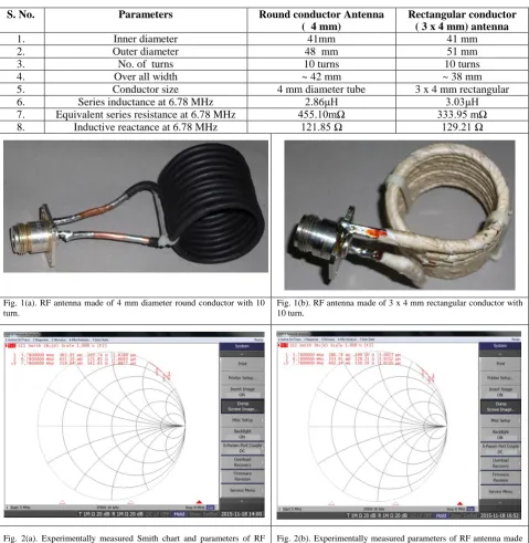
Two types of RF antenna of different shape conductors, each with 10 turns in single layer was developed and their electrical parameters were measured using VNA. The measured parameters are given in table-I. The RF antenna with3x 4 mm copper conductor was selected for simulation and experimental prototype. L-type impedance matching network was chosen and design procedure was carried out using ELSIE simulation package [16], and selected a series capacitor (CS) in series with RF antenna and parallel capacitor (CP) across the RF source. These selected capacitors were used in
II. RELATED WORK
The design and results of computational modelling of a high-power RF based H- ion source featuring an aluminum nitride plasma chamber is discussed in [1]. The paper [2] describes negative hydrogen ion source used worldwide for accelerators and their ignition system, along with the physics of surface and volume H- production. The article [3] describes a RF ion source with a back-streaming electron dump. The book [4] describes various ways to produce hydrogen plasma and the negative hydrogen ion production. The paper [5] describes the RF based negative ion source operating in continuous mode, with RF frequency 11 to 27.12 MHz for RF power of maximum 1400 W with planer spiral antenna. The article [6] describes RF driven external antenna multicusp ion source with plasma ignition system, using a separate 13 MHz antenna. The paper [7] describes an RF driven multicusp source, operated in both CW and pulsed mode to generate H- and various types of positive ion beams and production of metal ion beams, as an alternative to the arc-discharge sources. The paper [8] describes the RF based negative ion for H- production. In order to make clear the condition for the discharge initiation of the RF source, they developed a numerical model using the finite difference time domain Monte Carlo method to analyze the electron energy distribution function in RF field. The article [9] describes the various types of principle of RF coupling, power absorption, skin effect, discharge, electron temperature, energy loss. The paper [10] describes design and implementation of highly efficient, low cost 13.56 MHz, 1.5 kW RF source for inductively coupled plasma, for atomic emission spectroscopy. In paper, [11] an inductively coupled pulsed plasma source with an operating frequency of 29 kHz was described. The paper [12] describes, in detailed the inductively coupled plasma generation and their application for spectroscopy and their applications. The thesis [13] is written on the diagnostics and modelling of an inductively coupled RF discharge in hydrogen. The presentation [14] explains a different type of ion sources and the capacitive and inductively coupled RF plasma generation along with simulation and development of inductively coupled RF plasma ion source for different applications. The presentation [15] is on low pressure RF plasma sources for industrial applications, simulation and experimental results. The [16] is simulation software for RF network/circuit to generate Smith chart, input/output impedance, real and imaginary plot etc. for different frequency. The [17] is general purpose P-spice type simulation software for circuit analysis. The [18] paper is on the automatic frequency controller for power amplifiers used in bio-implanted applications. The patent [19] describes a compact matching network couples an RF power supply to an RF antenna in a plasma generator. The [20] paper explores some unique techniques and models for simulating amplifiers running in class C operation. The paper [21] gives the details of a new matching network with two tunable capacitors has been built and tested. The paper [22] gives the details on a FEM model was built to estimate the equivalent circuit parameters of the exciter. The chapter in [23] describes the three types of plasma generation for semiconductor industry (1) capacitive coupled plasmas (2) inductively coupled plasmas and (3) helicon wave sources. The thesis [24] is written on plasma thrusters and the performance characteristics of a compact electric thruster utilizing helicon plasma source is investigated. The book [25] incorporates a cutting-edge perspective on RF plasmas. It also covers basic plasma physics, including transport in bounded plasmas and electrical diagnostics.
III. RF ANTENNA DEVELOPMENT AND PARAMETER MEASUREMENTS.
TABLE: I
RF ANTENNA PARAMETERS
S. No. Parameters Round conductor Antenna
( 4 mm)
Rectangular conductor ( 3 x 4 mm) antenna
1. Inner diameter 41mm 41 mm
2. Outer diameter 48 mm 51 mm
3. No. of turns 10 turns 10 turns
4. Over all width ~ 42 mm ~ 38 mm
5. Conductor size 4 mm diameter tube 3 x 4 mm rectangular
6. Series inductance at 6.78 MHz 2.86μH 3.03μH
7. Equivalent series resistance at 6.78 MHz 455.10mΩ 333.95 mΩ 8. Inductive reactance at 6.78 MHz 121.85 Ω 129.21 Ω
Fig. 1(a). RF antenna made of 4 mm diameter round conductor with 10 turn.
Fig. 1(b). RF antenna made of 3 x 4 mm rectangular conductor with 10 turn.
Fig. 2(a). Experimentally measured Smith chart and parameters of RF antenna made of 4 mm diameter round conductor with 10 turn, using VNA.
Fig. 3(a) Model for impedance (50 Ω) matching network with CCL for 3 x 4 mm rectangular conductor, 10 turn RF antenna using ELSIE simulator.
Fig. 3(b) Model for impedance (50 Ω) matching network with LCL for 3 x 4 mm rectangular conductor, 10 turn RF antenna using ELSIE simulator.
IV. SIMULATION RESULTS OF IMPEDANCE MATCHIGN NETWORK USING ELSIE
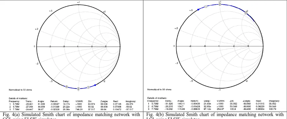
A simulation model of L-type impedance matching network for a RF antenna (0.33395 Ω and inductance 3.03μH) is shown in figure 3(a). CP (295 pF) parallel capacitor to the source is greater than CS (89 pF) a series capacitor to the
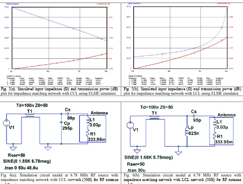
antenna, the simulated impedance of the network is ~ 50 Ω capacitive at 6.78 MHz. Figure 4(a) shows the simulated Smith chart of matching network impedance of circuit along with RF antenna. Impedance of the network is 63.574 Ω capacitive at 5.78 MHz, and drops to 37.517 Ω capacitive at 7.78 MHz. The phase angle of network impedance is ~ 89.90 degree at 6.78 MHz, is remain nearly constant from 5.78 to 7.78 MHz. The impedance of network drops and transmission power increases as source frequency increases, it is -27.354 db at 6.78 MHz is shown in figure 5(a). The VSWR of network is more than 1000 for 6.78 MHz operating source frequency.
Fig. 4(a) Simulated Smith chart of impedance matching network with CCL using ELSIE simulator.
Fig. 4(b) Simulated Smith chart of impedance matching network with LCL using ELSIE simulator.
V. STEADY STATE SIMULATION OF IMPEDANCE MATCHING NETWORK FOR RF ANTENNA USING
LT-SPICE.
Fig. 5(a). Simulated input impedance (Ω) and transmission power (dB) plot for impedance matching network with CCL using ELSIE simulator.
Fig. 5(b). Simulated input impedance (Ω) and transmission power (dB) plot for impedance matching network with LCL using ELSIE simulator.
Fig. 6(a). Simulation circuit model at 6.78 MHz RF source with impedance matching network with CCL network (50Ω) for RF antenna in LT-spice.
Fig. 6(b). Simulation circuit model at 6.78 MHz RF source with impedance matching network with LCL network (50Ω) for RF antenna in LT-spice.
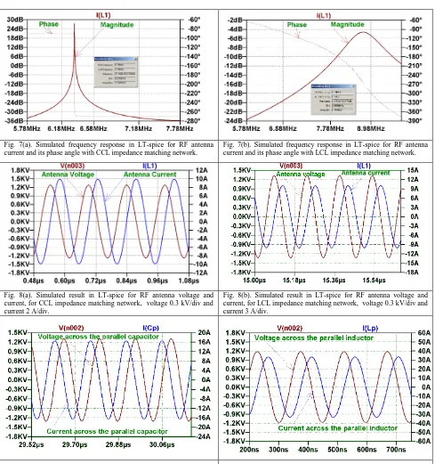
Fig. 7(a). Simulated frequency response in LT-spice for RF antenna current and its phase angle with CCL impedance matching network.
Fig. 7(b). Simulated frequency response in LT-spice for RF antenna current and its phase angle with LCL impedance matching network.
Fig. 8(a). Simulated result in LT-spice for RF antenna voltage and current, for CCL impedance matching network, voltage 0.3 kV/div and current 2 A/div.
Fig. 8(b). Simulated result in LT-spice for RF antenna voltage and current, for LCL impedance matching network, voltage 0.3 kV/div and current 3 A/div.
Fig. 9(a). Simulated result in LT-spice for voltage and current across the parallel capacitor (CP), for CCL impedance matching network, voltage
0.3 kV/div and current 4 A/div.
Fig. 9(b). Simulated result in LT-spice for voltage and current across the parallel inductor (LP), for LCL impedance matching network,
Fig. 10(a). Simulated result in LT-spice for source voltage and current, for CCL impedance matching network, voltage 0.2 kV/div and current 20 A/div.
Fig. 10(b). Simulated result in LT-spice for source voltage and current, for LCL impedance matching network, voltage 0.3 kV/div and current 2 A/div.
VI. EXPERIMENTAL PROTOTYPE TEST RESULTS
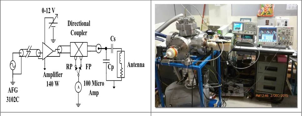
An experimental prototype test setup block diagram is shown in figure 11. It consists of main components, RF source, amplifier, directional coupler for power measurement and CCL impedance matching L-type network for RF antenna. The main components of these are given in Table-II. The 6.78 MHz RF signal is generated using Arbitrary Function Generator (AFG). This RF signal amplified by 140 W RF amplifiers (AN762-140). The output power of RF amplifier was adjusted by varying AFG signal amplitude. The experimental test setup of ICP generator ignition system is shown in figure 12. The antenna voltage measured using P5100A voltage probe and the current measured using P6021 current probe. Figure 13 shows the typical RF antenna voltage and current through it at 6.78 MHz, recorded at deposited RF power of 51.67 W. The peak voltage and current through it is~ 187 V and the peak is ~ 5.14 A respectively. These results closely match with the simulation results for a RF power of 50 W. The RF power coupled to antenna measured using Oscilloscope power analyzer, is shown in figure 14. The typical deposited power is 51.67 W. The hydrogen plasma ignites at coupled RF power of ~140 W, and once ignited the plasma is able to maintain at minimum RF power of 10 W.
AFG
3102C
Amplifier
140 W
Directional
Coupler
0-12 V
Cp
Cs
RP
FP
100 Micro
Amp
Antenna
A
Fig. 11. Schematic block diagram of experimental prototype test setup for a RF frequency of 6.78 MHz.
Fig. 13. Experimentally recoded RF antenna voltage 100V/div. and current through 2A/div.
Fig. 14. Experimentally measured RF power coupled by antenna to plasma chamber using Oscilloscope power analyzer, antenna voltage 100 V/div., current through it 2 A/div. and power 200 W/div.
TABLE.II
EXPERIMENTAL PROTOTYPE SETUP MAIN RF COMPONENTS LIST
Serial No. Component Value
1. Function generator (AFG) Tektronix AFG3102C 2. 2-30 MHz, 140 W RF amplifier Communication concept, AN762-140 3. Directional coupler Bird electronics, DPS 5010B, 100 µA
4. Series capacitor 85pF
5. Shunt capacitor 290pF
6. Connecting cable and connector RG-58, BNC type connectors 7. Voltage(V) and current (I) probe
( Make : Tektronix)
Voltage probe-P5100A Current probe- P6021
VII. CONCLUSION AND FUTURE WORK
[2] Douglas P. Moehs, Jens Peters and Joseph Sherman, “Negative Hydrogen Ion source for Accelerators”, IEEE Transactions on Plasma Science, vol. 33, no. 6, December 2005.
[3] Q.Ji, A.Sy and J.W.Kwan, “Radio frequency-driven proton source with a back-streaming electron dump”,Review of Scientific Instruments 81,02B312, 2010.
[4] Roy Middleton,” A Negative Ion CookBook” Department of Physics, University of Pennsylvania Philadelphia, October 1989.
[5] Bong -ki Jung, Y.H.An, W.H.Cho,J.J.Dang, “CW RF Cesium- free negative ion source development at SNU”, Department of Nuclear Engineering, Seoul National University, Seoul, Korea, 29 Jan 2013.
[6] Y.W.Kang, R. Fuja, T. Hardek, S-W. Lee, M.P. McCarthy, M.C. Piller, K. Shin, M.P. Stockli, A. Vassioutchenko, R.F. welton, “Development for performance improvement of SNS H-Ion Source RF systems,” in Proc. of Linear Accelerator Conference LINAC2010, Tsukuba, Japan, pp. 1019-1021.
[7] K.N. Leung, D.A. Bachman, P.R.Herz and D.S.McDonald, “RF driven ion source for pulsed or steady- state ion”, Nuclear Instruments and Methods in Physics Research, pp.291-294.
[8] S. Yoshinari, T. Hayami, R. Terasaki, A. Hatayama and A. Fukano, “Modelling of the RF discharge initiation in a negative ion source”, presented on 22 September 2009.
[9] W.Kraus, “RF Ion Sources”,Cern Ion School, June 2012.
[10] Anita Gupta,Yogesh Arondekar, S.V.G. Ravindranath, H. Krishnaswamy and B.N.Jagatap, “A 13.56MHz High Power and High Efficiency RF source”, 2013.
[11] Christian James Teske and Joachim Jacoby, “Pulsed low frequency inductively coupled plasma generator and applications”, IEEE Transaction on Plasma Science, vol. 36, no. 4, August 2008.
[12] Steve J.Hill,”Inductively Coupled Plasma Spectrometry and its applications”, Blackwell Publishing Ltd, second Edition, 2007.
[13] Victor Kadetov,” Diagnostics and modeling of an inductively coupled radio frequency discharge in hydrogen”, Ruhr –University Bochum, 2004.
[14] P Y Nabhiraj, “RF ion source and applications”, Accelerator Physics Group,2009.
[15] Valery Godyak, “Low Pressure RF Plasma Sources for Industrial Applications(ICP Versus CCP)”, Workshop on Radio Frequency Discharge, Dublin City University, Dublin, Ireland, 26-27 August 2011.
[16] James L.Tonee “ELSIE Software” Internet: http://elsie.software.informer.com,May 31,2015.
[17] “Linear Technology LTSpice IV Software” Internet: http://www.linear.com/designtools/software/#LTspice, Oct 21,2015
[18] Mahammad A.Hannan,Hussein A. Hussein, Saad Mutashar , “Automatic Frequency controller for power amplifiers used in Bio- Implanted Applications: Issues and Challenges,Sensors”,pp. 23843-23870, 2014.
[19] Daniel S. Pickard, Palo Alto, CA (US);Ka-Ngo Leung, Hercules, CA (US), U.S.Patent US 7298091, 2007.
[20] AmenahI.Kanaan, “Impedance matching network design for Class C power Amplifier”, Journal of Engineering and Development, vol.15, no.2,pp. 45-62, June 2011.
[21] Ki R.Shin, Yoon W.Kang, Maurice Piller and Alv E. Fathy, “Broadband Antenna Matching network design and application for RF plasma ion source”, in Proc. of 2011 Particle Accelerator Conference, New York, NY, USA, pp. 1990-1992.
[22] H.K.Yue, D.Li, D.Z.Chen,K.F.Liu,J.Huang, X.F.Li, C.Zhou, C.R.Wang and M.W.Fan, “Analysis and design of the matching unit for an RF driven plasma source for fusion purpose”, in Proc. of IPAC2013, Shanghai, China, pp. 389-391,2013.
[23] Francis F.Chen,“RF Plasma source for semiconductorprocessing”,May, 2005.
[24] N. Sinenian,”Propulsion Mechanisms in a Helicon Plasma Thruster” Plasma Science and Fusion center Massachusetts Institute of Technology Cambridge USA,
[25] Pascal Chabert and Nicholas Braithwaite,” Physics of radio frequency plasmas”, Cambridge University Press, New York, 2011.
BIOGRAPHY
Dharmraj V. Ghodke: was born in India, on October, 1968. He received his bachelor degree in Electrical Engineering from Shivaji University Kolhapur, Maharashtra, in 1991. He joined 35th batch BARC training school in 1991. After one year training in nuclear engineering and science, he joined Raja Ramanna Centre for Advanced Technology (RRCAT), in the department of atomic energy, since then working as a scientific officer. He received his Ph.D. degree from IITB Mumbai in 2008, from Electrical Engineering. He is currently working in RRCAT Ion Source Laboratory of Proton Linac and Superconducting cavities division. His current research interest includes electrical power sources for hydrogen ion sources, in DC, pulsed and RF for Proton Accelerators.
Rashmi Patel: was born in Jabalpur, India, on September, 1990. She received B.E. degree in Electronics and Communication Engineering from SRIST College Jabalpur, RGPV University, Bhopal, in 2012. She is currently studying toward the M. Tech. degree in Digital communication. Her research interests are wireless communication, antenna and RF.
Technology and Heading the Ion Source Laboratory of Proton Linac and Superconducting cavities division. He has served as TWAS-UNESCO Visiting Associate during 2003-2010. He did his postdoctoral fellowship at High Energy Accelerator and Research Organization, KEK, Japan. Currently serving as Professor of Homi Bhabha National Institute (HBNI) a deemed university of DAE at BARC Training School, RRCAT Indore. His research interest includes Ion Source design and development for Proton Accelerators, Spallation Neutron Source, Laser and Charged Particle Interactions with matter and their transport using Monte Carlo simulations.
Papiya Dutta: was born in India, on April, 1978. She received B.E. degree in Electronics and Communication Engineering from Hitkarini Engineering College Jabalpur, RGPV University, Bhopal, in 2001. She received M. Tech degree in Digital communication from NRI Institute of Information Science and Technology College Bhopal, RGPV University Bhopal in 2008. She has completed the course work in Ph.D., RDC on December 21, 2013 in Electronics and Communication Engineering from AISECT University. She is currently working in GGCT Jabalpur as Head of Department and Associate Professor of Electronics and Communication Engineering Department. She is an IEEE Member and Regional co-ordinator of IEEE MP Sub-section. Her research interest includes computer network, optical instruments and measurements and optical network.
Ranjan Kumar: was born in Nawada, Bihar (India) on Aug. 1989. He received the diploma in electronics engineering from Govt. Polytechnic Saharsa, Bihar (India) in 2011. He is currently working in Raja Ramanna Center for Advanced Techanology, Indore (India) as scientific assistant.
Bharat Kumar: Arya was born in Almora, Uttranchal (India) on Feb. 1972. He received the certificate of Industrial Training Institute, from Gandhi ITI Meerut (UP) in 1992. He initially worked in BM Elect India, Meerut for two years. He Joined RRCAT in 1994, Department of Atomic Energy, since then he is working as a technician. Currently he is working as foreman in the Ion Source Laboratory of Proton Linac and Superconducting cavities division.