International Journal of Research in Advent Technology (E-ISSN: 2321-9637) Special Issue
International Conference on Technological Advancements in Structures and Construction
“TASC- 15”, 10-11 June 2015
155
3. DETERMINATION OF EQUIVALENT STRUT WIDTH
Equivalent diagonal strut method is applicable to existing masonry infill and new panel added to an existing frame. Strut has the same properties as the infill panel it represents. Various expressions proposed by researchers/codes for equivalent strut width are given in the table 1.Based on validation, FEMA-356, Moghaddam and Dowlingand Euro code expressions are selected for single strut, double strut and three strut models respectively for the study.
Table 1. Expressions for equivalent strut width
Researchers/Code Equivalent Strut Width (W)
Holmes W = dz/3
Mainstone W = 0.175(λh)
0.4
λh =H[Emtsin2θ/4EcIcHm)]
Hendry
W = 0.5[αh + αL]½
αh= [EcIcHm/2Emsin2θ]¼
αL= [EbIbL/2Emsin2θ]¼
Liaw & Kwan W = [0.95HmCos θ/√λh]
Pauley&Priestly W =0.25 dz
Moghadom
&Dowling (1988) W=dz/6
Smith &
Carter W = π/2 λh
Eurocode 8 W=0.15 dz
FEMA 356 W=0.175[λh H]-0.4Hm
Durrani and Luo (1994)
W = dz [ γ sin 2θ] ¼ γ = [0.32√sin2θ(H4Eit/mEcIcb)
-0.1
] m= 6[1+[6αtan(EbIbH/EcIcL)/π]]
Cavaleria &Papia (2003)
W=d[c/z[1/(λ*
)β]] λ*
=(Ed th'/ Ef Ac) [h '2
/l'2+Acl'/4Abh']
c=0.249-0.0116υ+0.567υ2 β=0.146+0.0073υ+0.126υ2 P100/1-2006 W = dz /10
MSJC ( 2007) W= 0.3/ λh cos θ
Where,
dz= Diagonal length
H= Height of frame
Hm= Height of masonry infill
Em= Elastic modulus of infill
αh= Ratio of column contact length to height
ofcolumn.
αL = Ratio of beam contact length to span of
thebeam.
4. DESCRIPTION OF THE MODELS
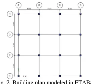
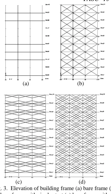
The theoretical approach given by equivalent diagonal strut model is applied to buildings having 5, 10, 15, 20 stories. All the buildings have a symmetrical layout with typical story height of 3.2m and basement height 1.5m. Building plan chosen for the study is shown in fig. 2. The bay length along both directions is taken as 5m. Column sizes are 0.4m x 0.4m, 0.46m x 0.46m, 0.51m x 0.51m, 0.53m x 0.53m for 5, 10, 15 and 20 storied buildings respectively. Beams are 0.3m x 0.5m in size. Thickness of floor slab, roof slab and infill masonry wall are 150mm, 120mm and 200mm respectively for all the models. Young’s modulus for infill panels are taken as 2300 N/mm2. Strut dimensions are determined according to the methods described in table 1. Figure 3 shows elevation of 10 storeyed building frame modeled as bare frame (BF), bare frame with single strut (BFSS), bare frame with double strut(BFDS) and bare frame with triple strut (BFTS).
Fig. 2. Building plan modeled in ETABS
5. ANALYSIS METHOD
(a)
(c)
Fig. 3. Elevation of building frame (a) bare frame (b) bare frame with single strut (c) bare frame with
double strut (d) bare frame with triple
6. RESULTS AND DISCUSSION
Study on effect of masonry infill walls on behaviour of reinforce concrete frame buildings under seismic force was studied using different
models. The infill walls were usually considered as non-structural elements and were not included in analysis and design. However, the fact is far from
Fig. 4. Ground motion data of Bhuj -1
-0.5 0 0.5 1 1.5
0 5
A
cc
el
er
at
io
n
(
g
)
(b)
(d)
. Elevation of building frame (a) bare frame (b) bare frame with ) bare frame with triple strut
RESULTS AND DISCUSSION
tudy on effect of masonry infill walls on behaviour of reinforce concrete frame buildings under seismic force was studied using different equivalent strut . The infill walls were usually considered as structural elements and were not included in the analysis and design. However, the fact is far from
reality as the infill walls would definitely interact with the enclosing frame especially under seismic forces.
6.1. Effect of strut models
A comparative study, based on the models proposed was carried out to assess a suitable model for masonry infills in RC frames. The effect of infill on the member forces in beams and columns were
This is one of the most important parameter in the design of any building structure
with an increase in number of struts
observed in the structural responses such as period, maximum storey displacement, maximum beam moment, and maximum column axial force 6.1.1. Time period
Modal analyses were carried out to obtain the time period for bare frame and infilled frame models. sources of mass were from the dead load of infill walls and the frame elements. The dead load from the infill walls were applied as the uniformly distri load along the beams. The equivalent diagonal strut's mass is not included but its stiffness was included in the analysis since the models were studied under the in-plane loads. Variation of fundamental period with no. of storey is shown in fig. 6.
of time period with respect to mode
building. Similar trend was also observed for and 20 storeyed models. It is observed
BFTS model shows similar trend is different from the other two.
obtained using empirical equation in IS 1893:2002 is higher compared to BFSS and BFTS models
6.1.2. Maximum storey displacement
Maximum storey displacement models is shown in figure 7. Fig. 4. Ground motion data of Bhuj, Northridge and Kobe earthquake
10 15 20
Time (sec)
156 reality as the infill walls would definitely interact with the enclosing frame especially under seismic forces.
A comparative study, based on the models proposed carried out to assess a suitable model for masonry The effect of infill on the member forces in beams and columns were studied. This is one of the most important parameter in the structure. Its observed that h an increase in number of struts, variation is observed in the structural responses such as time y displacement, maximum beam moment, and maximum column axial force.
Modal analyses were carried out to obtain the time period for bare frame and infilled frame models. The sources of mass were from the dead load of infill walls and the frame elements. The dead load from the infill walls were applied as the uniformly distributed load along the beams. The equivalent diagonal strut's mass is not included but its stiffness was included in the analysis since the models were studied under the f fundamental period with y is shown in fig. 6. Fig. 7 shows variation of time period with respect to mode for 10 storied building. Similar trend was also observed for 5, 15 It is observed that BFSS and similar trend, while BFDS model
The time period
obtained using empirical equation in IS 1893:2002 is higher compared to BFSS and BFTS models
Maximum storey displacement
y displacement for different strut . The graph shows that earthquake
25 30
International Journal of Research in Advent Technology (E-ISSN: 2321-9637) Special Issue
International Conference on Technological Advancements in Structures and Construction
“TASC- 15”, 10-11 June 2015
157 under all earthquake BFSS and BFTS with5, 10
stories have less maximum story displacement compared to BF and BFDS models. Here it is observed that both BFSS and BFTS show reasonable value of storey displacements.
6.1.3. Maximum column axial force
Column axial forces are observed to be maximum in bottom stories. In fig. 8 it shows that that is a drastic increase in maximum column axial force due to the presence of infill under Kobe and Northridge earthquakes. It is also observed that for all the models
0 5 10 15 20 25
0 100 200 300 400 500 600
N
o
.
o
f
S
to
re
y
Maximum Storey Displacement (mm)
Northridge_BF Northridge_BFSS Northridge_BFDS Northridge_BFTS Bhuj_BF Bhuj_BFSS Bhuj_BFDS Bhuj_BFTS Kobe_BF Kobe_BFSS Kobe_BFTS Kobe_BFDS
Fig. 7. Maximum storey displacement vs. number of storey 0
0.2 0.4 0.6 0.8 1 1.2 1.4
0 1 2 3 4 5 6 7 8 9 10 11 12
T
im
e
P
er
io
d
(
se
c)
Mode
BF BFSS BFDS BFTS
Fig. 6.Variation of time period with mode
0 5 10 15 20 25
0 2500 5000 7500 10000 12500 15000
N
o
.
o
f
S
to
re
y
Maximum Column Axial Force (kN)
Northridge_BF Northridge_BFSS Northridge_BFDS Northridge_BFTS Bhuj_BF Bhuj_BFSS Bhuj_BFDS Bhuj_BFTS Kobe_BF Kobe_BFSS Kobe_BFDS Kobe_BFTS
0 5 10 15 20 25
0 0.5 1 1.5 2 2.5 3
N
o
.
o
f
S
to
ry
Time Period (sec)
BF
BFSS
BFDS
BFTS
IS 1893:2002
158 due to presence of infill, 15 storied building has
maximum column axial force. This increase in axial load will result in the failure of columns. This may also result in yielding of columns prior to yielding of beams. The change in behaviour was due to change in load transfer mechanism of the building models from frame action to truss action, due to presence of masonry infill walls.
6.1.3. Maximum beam moment
Variation of maximum beam moment due to presence of infill is shown in fig. 9. It is observed the maximum beam moment reduces due to presence of infill walls. It is seen that beam moment is maximum for 10 storied buildings for Bhuj and Kobe earthquakes. For Northridge earthquake it is maximum for 5 storied building.
6.2. Effect of infill thickness
To study the effect of infill wall thickness on building models, 100mm, 200mm and 300mm thickness were adopted. Structural response is examined in terms of story displacement and story shear. When the thickness of the infill wall was increased, the stiffness and strength of the building models increased.
6.2.2. Storey Displacement
Plot of story displacement with height of building is shown in fig. 10.It is observed that for all models under all the three earthquakes, storey displacement decreases with increase in thickness. As the thickness increases buildings becomes stiffer and attract more forces there by reducing storey displacement.
6.2.2. Story Shear
Story shear experienced for three different infill thickness are sketched in fig. 11. Results show that storey shear increases with increase in infill wall
thickness. For all the models, shear is found to be maximum at bottom storey. Base shear is found to be maximum for building with 300mm infill thickness under Kobe earthquake.
6.3. Effect of elastic modulus of infill
To study the effect of elastic modulus of infill wall, three types of infills are considered namely – weak infill, intermediate infill and strong infill, which has a Young’s modulus of 2300 MPa, 3800 MPa and 4200 MPa respectively. The values of Young’s modulus are taken from previous literature (Hemant B. K., et al, 2007). The effect of infill on inter-story drift and column axial load were studied.
6.3.1 Inter-story Drift
The drift value has a particular importance of serviceability requirement. In general, the effect of infill panel is to reduce the seismic demand of a building structure both in terms of lateral displacement as well as inter story drift. As expected, the infill has a better response during earthquake excitation. It is observed that is a considerable reduction in inter-storey due to presence of strong infill walls. In fig. 12, it shows that inter-storey drift is maximum for lower stories for all the models.
0 5 10 15 20 25
0 200 400 600 800 1000 1200
N
o
.
o
f
S
to
re
y
Maximum Beam Moment (kNm)
Northridge_BF Northridge_BFSS Northridge_BFDS Northridge_BFTS Bhuj_BF Bhuj_BFSS Bhuj_BFDS Bhuj_BFTS Kobe_BF Kobe_BFSS Kobe_BFDS Kobe_BFTS
International Journal of Research in Advent Technology (E-ISSN: 2321-9637) Special Issue
International Conference on Technological Advancements in Structures and Construction
“TASC- 15”, 10-11 June 2015
159 6.3.2.Column axial load
Figure 13 represents variation of column axial load with respect to building height. It is observed that there is not much effect on column axial load, when building models are subjected to Bhuj and Kobe earthquakes. But for Northridge earthquake, there is a drastic increase in column axial load due to the presence of strong infill.
Fig. 10. Variation of storey displacement with building height
0 5 10 15 20 25 30 35
0 10000 20000 30000 40000 50000
H
ei
g
h
t
(m
)
Storey Shear (kN)
Bhuj_100 Bhuj_200 Bhuj_300 Northridge_100 Northridge_200 Northridge_300 Kobe_100 Kobe_200 Kobe_300
Fig. 11. Variation of storey shear with building height 0
5 10 15 20 25 30 35
0 50 100 150 200 250 300 350 400
H
ei
g
h
t
(m
)
Storey Displacement (mm)
Bhuj_100
Bhuj_200
Bhuj_300
Northridge_100
Northridge_200
Northridge_300
Kobe_100
Kobe_200
Kobe_300
0 5 10 15 20 25 30 35
0 0.005 0.01 0.015 0.02
H
ei
g
h
t
(m
)
Inter Storey Drift
Bhuj_weak
Bhuj_intermediate
Bhuj_weak
Northridge_weak
Northridge_intermediate
Northridge_strong
Kobe_weak
Kobe_intermediate
Kobe_strong
0 5 10 15 20 25 30 35
0 2000 4000 6000 8000 10000
H
ei
g
h
t
(m
)
Column Axial Load (kN)
Bhuj_weak
Bhuj_intermediate
Bhuj_strong
Northridge_weak
Northridge_intermediate
Northridge_strong
Kobe_weak
Kobe_intermediate
Kobe_strong
160
7. SUMMARY AND CONCLUSION
A study on effect of masonry infill walls on behaviour of reinforced concrete frame buildings under seismic force was studied using different infill models. The infill walls were usually considered as non-structural elements and were not included in the analysis and design. However, the fact is far from reality as the infill walls would definitely interact with the enclosing frame especially under seismic forces. The effect of masonry infills on seismic behaviour of RC frame buildings with different heights was studied by linear time history analysis. The infill walls were modeled as compressive equivalent diagonal strut using single, double and triple strut model. The parametric study on thickness of infill, fundamental period and elastic modulus of infill walls were also done.
The results obtained shows that calculation of earthquake forces by treating RC frames as bare frames without regards to masonry infill leads to under estimation of base shear and column axial force. The results from the different models on fundamental periods shows that masonry infill walls had significant effect (decreases the time period) on the dynamic characteristics like fundamental period of the buildings. The fundamental periods were dependent on the area of infill walls. The results of analysis demonstrated that masonry infill walls highly increased the stiffness and strength of a structure.
The other parametric study that was done was infill wall thickness. The results indicated that the structural responses were affected with infill thickness. The increased in infill thickness decreased the fundamental period and roof displacement. With the increase in thickness, story shear and column axial load increases.
Young’s modulus is found to be very significant in seismic analysis. Single strut model is better to be used in analysis regarding the general behavior of infill frames. Three strut model is the appropriate approach for determining the local effects of frame infill interaction. Strong infill panel gives better seismic performance i.e. strength and stiffness is higher compared to weak and intermediate infills.
REFERENCES
[1] Moghaddam, H. A., and Dowling, P. J. (1987). “The state of the art in infilled frames.” ESEE Research Rep. No. 87-2, Imperial College ofScience and Technology, Civil Engineering Dept., London, UK.
[2] Mainstone, R. J. (1974). Supplementary note on the stiffness and strengths of infilled frames, Building Research Station, Garston, UK. Smith, B. S. (1967). “Methods for predicting the lateral stiffness and strength of multi-storey infilled frames.” Build. Sci., 2(3), 247–257.
[3] FEMA 356, prestandard and commentary rehabiltation of buildings. “American Society Of Civil Engineers For The Federal Emergancy Management Agency, Washington.”
[4] Saneinejad, A., and Hobbs, B. (1995). “Inelastic design of infilled frames.”ASCE., 121(4), 634– 650.
[5] Asteris, P. G. (2005). “Closure to ‘Lateral stiffness of brick masonry infilled plane frames’ by P. G. Asteris.” ASCE., 131(3), 523–524 [6] Liauw T.C., and Kwan K., “Non-linear behavior
of non-Integral infilled frames”, Computers and Structures, Vol.18, No.3, pp.551-560, 1984. [7] Indian Standard, Criteria for earthquake resistant
design of structures, IS 1893(Part 1): 2002, Bureau of Indian Standards, New Delhi, India. [8] Murty, C.V.R., and Jain, S.K., 2000. Beneficial
influences of masonry infills on seismic performance of RC frame buildings, Proceedings, 12th World Conference on Earthquake Engineering, New Zealand, Paper No.1790. [9] Stafford, S. B. (1966). Behaviour of squared
infilled frames. ASCE Journal of Structural Division 92(ST1), 381–403.
[10]Crisafulli, F. G. (1997). “Seismic behaviour of reinforced concrete structures with masonry infills.” Ph.D. thesis, Univ. of Canterbury, Christchurch, New Zealand.
[11]Crisafulli, F. J., Carr, A. J., and Park, R. (2000). “Analytical modelling of infilled frame structures—A general review.” Bull. New Zealand Soc. Earthquake Eng., 33(1), 30–47. [12]Diptesh Das and C.V.R. Murty, Brick masonry
infills in seismic design of RC framed building, The Indian Concrete Journal, July 2004
[13]Mulghand, G.; Kulkarni, A..; (2011): Seismic assessment of RC frame buildings with brick masonry infills, International journal of advanced engineering sciences and technologies, 30(1–7), pp. 140–147
[14]Mallik, R.; Polyakov, A.; (1967): The behavior of infilled frames under static loading, University of California Berkley, 38, pp. 639-656. S5.
[15]Liauw, T. C., and Kwan, K. H. (1984). “Nonlinear behaviour of non integral infilled frames.” Comput. Struct., 18, 551–560.
[16]Holmes, M. (1961). “Steel frames with brickwork and concrete infilling.”ICE Proc., 19(4), 473– 478.
[17]Durrani, A. J., and Luo, Y. H. (1994). “Seismic retrofit of flat-slab buildings with masonry infills.” Proc., NCEER Workshop on Seismic Response of Masonry Infills, National Center for Earthquake Engineering Research(NCEER), Buffalo, NY.