Intelligent Lighting Network Applications Using Can Bus
S.Ramakrishnan1, T. Muni Prakash2
1Asst. Prof. EEE Department New Horizon College of Engg., Banglore, Karnataka, India
2Sr.Asst. Prof. EEE Depaartment New Horizon College of Engg., Banglore, Karnataka, India
ABSTRACT
:
In this paper describes a new embedded system based on CAN bus protocol for remote monitoring and controlling of lighting networks, where the network nodes are lighting lamps and environment sensors. The applications such as: light dimming control of a single lamp, or a group one, through one lighting network node having an environment sensor. The embedded system was implemented in a small prototype lighting network based on CAN 2.0B with three 28 Watts fluorescent T5 lamps, one 13.86 Watts HBLED lamp composed of six LEDs, and two environment sensors. The proposal can be expanded to more than 2048 nodes and other kind of lighting lamps can be used. Individual and group control for dimming and turning on/off, fault detection condition of lamp tubes and environment sensors monitoring. The main characteristic of the embedded system is its non-master capability, allowing implementation of a novel fully functional CAN bus lighting network with a reliable two wire remote control. Applications for this CAN bus lighting network include building management or studio lighting where it is desired to control lamps for saving energy consumption, performing lamp maintenance or creating precision lighting effects.
I. INTRODUCTION
The term ”intelligent lighting system” refers to a system where multiple lighting fixtures are connected to a network, The intelligent lighting system providing the necessary light dimming and on/off to desired location actually construct a fundamental experiment system based on that concept; and verify the effectiveness of the newly developed control method. . The use of electronic embedded systems for driving fluorescent lamps has been notably increased in last years, the main reason is their extensive advantages compared with electromagnetic ballasts. The design goal has been extended to provide the right light using more efficient systems with design issues like: low harmonic distortion, high power factor, light dimming and maintenance-oriented features, reducing in this way lighting energy consumption and maintenance time response. One important lighting feature is the lamp remote controllability, which requires lamp capability to send and receive useful information, using some reliable communication protocol through a network, and allowing a complete remote control of a lighting environment.
configuration is implemented with CAN nodes composed of: microcontroller, CAN controller and CAN transceiver, an N nodes network is shown in Figure 1.
Fig1. General Can Bus Standard Configuration
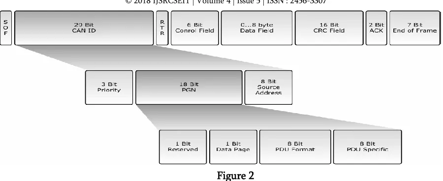
The identifier field length of CAN 2.0B protocol is 29 bits. Data frames are used to transmit up to 8 bytes of information from one specific CAN node to one or several CAN nodes. An 29 bits identifier field length allows more than 2048 available identifiers or logical addresses, where each one can be assigned as one specific functional node. J1939 provides a communication protocol over a CAN network. The CAN network is comprised of two or more interconnected Electronic Control Units (ECUs).As per the SAE J1939-11 specification. The ECUs are connected using linear shielded twisted pair wiring, with a data rate of 250 Kbits/second.
II.BASIC CONCEPTS OF CAN
CAN has the following properties
Prioritization of messages
Guarantee of latency times
Configuration flexibility
Multicast reception
Multimaster
Error detection and signaling
Figure 2
III.FUNCTION OF LIGHTING NETWORK
Block diagram of lighting network using CAN bus
Block diagram of embedded system
and data field includes one byte instruction code. In the same way two phases are done in a node-PC communication where a specific node message is received by the PC, such as lamp fault condition or sensor monitoring. In first phase a CAN data frame is sent by the specific node to the CAN node 0, including its 11 bits identifier and a fault message code. In second phase CAN node 0 sends the received message code and node identifier, through the serial port, to the PC in a 5 byte format.
Circuit of microcontroller connected to fluorescent lamp & fault detection
Fluorescent lighting lamp at 100%, 50%, 10%.
IV.CONCULSION
The embedded system based on CAN bus protocol for two wire remote monitoring and controlling of lighting networks is presented. The embedded system was implemented in a small prototype lighting network with three fluorescent lamps, one HBLED lamp, and two environment sensors namely occupancy and daylight sensor were used. According to obtained results the proposed system performed established network functions successfully, allowing the implementation of a novel fully functional CAN bus lighting network with a reliable remote control. The non master-slave scheme characteristic of CAN bus protocol allows the addition of intelligent lighting network features.
V.REFERENCES
[1] T. Marchesan, G. Dernardin, R. Silveira, A. Campos, and R. Prado, “Development of a control fieldbus for HPS electronic ballasts using power lines,” Proc. of 35th Annual IEEE Power Electronics Specialist Conference, Aachen, Germany, pp. 3593-2596, 2004.
[2] K. Kutluay, I. Cadirci, A. Yafavi, and Y. Cadirci, “Dual 8b microcontrollers–digital control of universal telecommunication power supplies,” IEEE Ind. Appl. Magazine, vol. 12, no. 1, pp. 59-67 Jan/Feb 2006. [3] C. Contenti and T. Ribarich, “Digitally Addressable DALI Dimming Ballast,” Proc. Applied Power Electronics Conference and Exposition, Dallas Texas, USA, pp. 936-942, 2002.
[4] J. M. Alonso, J. Ribas, J. J. del Coz, A. J. Calleja, E. L. Corominas, and M. Rico-Secades, “Development of a distributive control scheme for fluorescent lighting based on LonWorks technology,” IEEE Trans. On Industrial Electronics, vol. 47, no. 6, pp. 1253-1262, Dec. 2000.
[5] M. Miki, T. Hiroyasu, and K. Imazato. “Proposal for an intelligent lighting system, and verification of control method effectiveness,” Proc. on IEEE Conference on Cybernetics and Intelligent Systems, pp. 520-525, ingapore, 2004.
[6] ALONSO J M, RIBAS J, DEL COZ J J, CALLEJA A J, LOPEZ E, RICO-SECADES M Intellignt Control System for Fluorescent Lighting Based on LonWorks Technology. Proc IEEE IECON, Vol.1998, No.Vol.1, Page92-97, (1998)
[7] 1. A Comprehensible Guide to Controller Area Network by Wilfried Voss [8] J1939-based application profiles by Holger Zeltwanger – CiA.