Theft Detection and Alert System
Kaustubh Bawdekar
1, Rajkrishna Das
2B.E. ENTC, Dept. of Electronics and Telecommunication MIT COE, Pune, India
B.E. ENTC, Dept. of Electronics and Telecommunication, MIT COE, Pune, India
ABSTRACT: In our project we aim to detect any attempt to steal the inventory from an agricultural land. We have used an RFID Reader and Tag, Arduino Uno Microcontroller, a GPS and a GSM module. Additionally, we have also developed an Android application that lets the user track the whereabouts of his inventory, in the event of it being stolen. In the app a message will be sent at a fixed interval, the message contains GPS Co-ordinates of the missing Inventory and an Alert message.
KEYWORDS: Theft, Detection, Alert
.
I.INTRODUCTION
RFID (Radio Frequency Identification) is an extremely fast growing technology that employs electromagnetic fields to transfer data. Mostly this data transfer consists of identification and/or tracking of target object wirelessly through ‘tags’. These tags have electronically imprinted data which maybe read using a variety of
different methods, depending upon which the tags may be classified as active, passive or battery assisted. The data is read using two-way radio transmitter- receiver. RFID technology is used in many applications such as tracking of shipment, animals, vehicles and more recently even humans. Unlike the barcode, RFID doesn’t require a clear line of sight between the tag and the reader. The RFID market is expected to grow to over 20 billion USD by 2014.Our main aim would be to employ low power, long range RFID smart tags to track mechanized farming equipment, other farm inventory and to develop a Smartphone application for the same. Traditional means of monitoring may prove to be too cumbersome and have many loopholes which may be exploited. The Smartphone application will provide real time monitoring of the inventory as well as generate an anti-theft alarm should the need be. In this project we try to minimize the cost of the monitoring system. Main objective is to design a system that can be easily installed and to provide platform for further enhancement.
II. RELATED WORK
Our project requires equipment that can communicate with the user in a duplex way. So that when the alert message has been tackled by the user, the user can send a simple message and can turn off the alert system. So we decided to choose the following components.
An RFID READER AND CARD (EM 18)
A GSM module (SIM 900A)
A GPS module
Arduino Uno ATMEGA 328.
Each component has the following features
Three timers/counters
GSM MODULE SIM900A
Built in RS232 to TTL or vice versa logic converter (MAX232) Configurable Baud Rate
Audio Interface connectors (in and out) Input Voltage 5V to 12V DC
GPS MODULE
165dBm tracking Sensitivity Full ESD protection in all pins
Embedded with one 4 MBits flash memory USB 2.0 Full speed compliant interface
RFID READER AND CARD EM18 Serial TTL Output
Along with two RFID cards
Excellent read performance without any external circuit. Compact Size, Cost Effective.
Because of all the above features of the components, the system has optimal performance and can send alert messages to the user at a predefined interval of time.
III. BLOCK DIAGRAM OF THE SYSTEM AND ITS DESCRIPTION
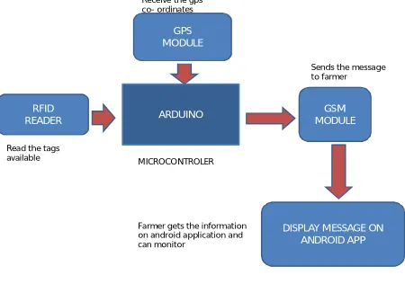
A detailed block diagram of our system has been shown below in fig.1 the block diagram describes the order in which the detection takes place. It also cites in all the Components that we have used in the System. The logical flow of events can also be pointed out using the block diagram.
Fig. 1 Block Diagram
As seen in the block diagram we have interfaced a microcontroller (ARDUINO) with the RFID tags and a GPS module.
When the agricultural instrument is attempted to be stolen the RFID tags come into play and the equipment which is been stolen gets activated.
ARDUINO GSM
MODULE RFID
READER
DISPLAY MESSAGE ON ANDROID APP GPS
MODULE
Read the tags available
Receive the gps co- ordinates
MICROCONTROLER
Sends the message to farmer
By using the GPS (GLOBAL POSITIONING SYSTEM) we get the co-ordinates i.e. the latitude and longitude .Now by using GSM (GLOBAL SYSTEM FOR MOBILE COMMUNICATION) we are sending message to the farmer.
The farmer receives the message on the android application and is informed that his instrument is being stolen.
Due to the GPS the user is able to track the whereabouts of his instruments, thus enabling the perpetrators of crime to be caught.
IV. SYSTEM DESIGN
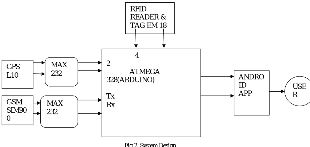
The system design that is proposed below, gives a detailed view of the elements in this system, and the interconnections between them. It gives the details about the various GPIO Pins used in Arduino Microcontroller as well as the various components used.
Fig 2. System Design
As seen from the System Design Block Diagram, the GSM module SIM 900 Communicates with the ATMEGA 328, using the RS232 protocol, so we use MAX 232 line converter.
Similarly the GPS module communicates with the ATMEGA 328 using the MAX 232 line converter. We use MAX 232 to convert RS232 signals to TTL compatible Voltage levels.
So it eases the communication.
Similarly the RFID reader module sends signal to ATMEGA 328 When it sends the signal that the RFID card is read, it triggers the GPS module, when the co-ordinates are obtained , an SMS is sent along with the coordinates to the Android application, which the user can use.
RFID
READER &
TAG EM 18
GPS
L10
MAX
232
4
2
ATMEGA
328(ARDUINO)
Tx
Rx
ANDRO
ID
APP
USE
R
MAX
232
GSM
V. IMPLEMENTATION OF THE SYSTEM.
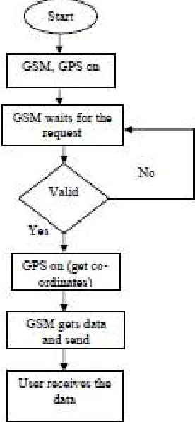
This project mainly consists of four units: A GPS Module, A GSM Module, RFID READER and Arduino microcontroller. When the equipment is being stolen the RFID tag gets triggered. Once it gets activated the GPS and GSM starts. GPS is one of the technologies that are used in a huge number of applications today. One of the applications is tracking your vehicle and keeps regular monitoring on them. This tracking system can inform you the location and route travelled by thief, and that information can be observed from any other remote location. It also includes the web application that provides you exact location of target. This system enables us to track target in any weather conditions. This system uses GPS and GSM technologies.
Fig 3: GPS AND GSM WORKING
The farmer now receives the message on his cell phone. The message will be displayed on his android app. Since this message is of higher priority the android app will beep and alert the farmer.
The farmer will now be able to know the position of his item and will be able to monitor it on his android app. The android application will constantly update the farmer about his item.
The farmer will also be able to track the path followed and know where the thief is actually taking the equipments
VI. RESULTS
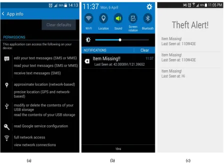
Here is a Screenshot of the App Interface with the Alert Message and Google maps co-ordinates of the stolen Inventory.
(a) (b) (c)
Fig 4 The Application Interface (a) the permissions required while installation (b) the toggle bar notification generated by the application (c) the application interface with alerts messages.
VII. CONCLUSION
In this project, we focused on the ability of the GPS and GSM module to detect the range of objects on the farm. The experiments indicate that the low cost GPS and GSM module are able to give reliable information
to the farmer. The results obtained show satisfactory results. Tracking system is becoming increasingly important in large cities and it is more secured than other systems. It is completely integrated so that once it
is implemented in all tractors, water-pumps, farming equipments then it is possible to track anytime from anywhere. It has real-time capability. This system has many advantages such as large capability, wide areas
Range, low operation costs, effective, Strong expandability and Easy to use in vehicle traffic administration. Upgrading this setup is very easy which makes it open to future a requirement which also makes it more efficient
VIII. ACKNOWLEDGEMENT
helping hand in all possible ways. We are also deeply indebted to all the teaching and non-teaching staff for the facility provided and their critical advice and guidance.
REFERENCES
[1] Hu Jian-ming; Li Jie; Li Guang-Hui, "Automobile Anti-theft System Based on GSM and GPS Module," Intelligent Networks and Intelligent Systems (ICINIS), 2012 Fifth International Conference on , vol., no., pp.199,201, 1-3 Nov. 2012
[2] Nagaraja, B. G.; Rayappa, R.; Mahesh, M.; Patil, C.M.; Manjunath, T. C., "Design & Development of a GSM Based Vehicle Theft Control System," Advanced Computer Control, 2009. ICACC '09. International Conference on , vol., no., pp.148,152, 22-24 Jan. 2009
[3] Fleischer, P.B.; Nelson, A.Y.; Sowah, R.A.; Bremang, A., "Design and development of GPS/GSM based vehicle tracking and alert system for commercial inter-city buses," Adaptive Science &Technology (ICAST), 2012 IEEE 4th International Conference on , vol., no., pp.1,6, 25-27 Oct. 2012
[4] Iman M. Almomani, Nour Y. Alkhalil, Enas M. Ahmad, Rania M. Jodeh “Ubiquitous GPS Vehicle Tracking and Management System”, IEEE Jordan Conference on Applied Electrical Engineering and Computing Technologies (AEECT) 2011
[5] http://www.microchip.com [6] http://en.wikipedia.org/wiki/gps [7] www.engineersgarage.com
[8] http://www.adafruit.com/products/164
[9] http://www.makershed.com/product_p/mkad15.htm [10] https://www.sparkfun.com/products/255