ABSTRACT
YANG, CHEN. Preform Design for Forging and Tube Hydroforming Processes. (Under the direction of Dr. Gracious Ngaile.)
In the metal forming process, preforming is widely used to deform the work piece into a
suitable shape that can form the required product successfully without forming defects
and excessive waste of material in the final process. A proper preforming stage can
improve the product quality, reduce forming stages and minimize manufacturing cost.
Preform design problems are encountered in various metal forming processes. However,
this research focuses on the preforming problems in the forging process and Tube
Hydroforming process.
Preform Design in Forging Process: Preform design is critical for multi-stage forging
processes to ensure the production of defect-free parts. Moreover due to the geometry
and material flow complexities in forging processes, finding the optimal preform shapes
could be difficult and time consuming.
An efficient design methodology based on geometrical resemblance is proposed for the
preform design in forging process. The premise of this methodology is such that the
initial and subsequent simulations are carried out by constructing a slightly larger part
which geometrically resembles the desired part. Initial FEA simulation of the larger part
is performed with reasonably guessed preform shape which may allow the occurrence of
forming defects or flash formation. Then a series of intermediate resembling parts
between the largest part and the desired part are constructed. The undeformed shape
corresponding to the intermediate part could be obtained by backward tracing of material
flow from the simulation results of the larger part. This undeformed shape is then taken
forging and extrusion processes have been carried out. The methodology has been proven
to be computationally efficient since it requires fewer numbers of iterations.
Preform Design in Tube Hydroforming Processes: In the last decade, the tube
hydroforming process has received increased attention in the automotive and aerospace
industries owing to its advantages such as part consolidation, weight reduction, and
better part quality over stamped and welded assemblies. However, an incoming straight
tube may need to be preformed due to the shape complexity of the tubular part and
material flow limitation. One such preforming process, axial crushing, is used to
accumulate the material in the die cavity by forming axisymmetric wrinkles on the tube.
However, the knowledge of how to axially crush the tube in the tube hydroforming
process is still limited.
In this research, a two-stage preforming process based on the wrinkle formation is
developed for the Tube Hydroforming process to accumulate material in the forming
zone so that the thinning rate can be reduced and formability can be improved. In
preforming stage one, the wrinkle onset is triggered with limited axial compression. In
preforming stage two, the wrinkle grows stably and uniformly to a certain height. Then
the preformed wrinkles are flattened to conform to the die shape in the final tube
hydroforming process. An analytical model based on the bifurcation analysis and
post-buckling analysis of the elastic-plastic circular cylinder under internal pressure and
axial compression is used to study wrinkle evolution characteristics. The analytical
results offer guidance to the process design of the two-stage preforming process. To
validate this methodology, preform die sets for three axisymmetric parts were designed
and tube bulging experiments were carried out on SS 304 tubing and Al 6061 tubing.
Through this methodology, expansion rates of the bulging process are significantly
by Chen Yang
A dissertation submitted to the Graduate Faculty of North Carolina State University
in partial fulfillment of the requirements for the degree of
Doctor of Philosophy
Mechanical Engineering
Raleigh, North Carolina
2011
APPROVED BY:
_______________________________ ______________________________ Dr. Gracious Ngaile Dr. Gregory Buckner
Committee Chair
DEDICATION
Dedicated to
my wife Hua
for her endless love, encouraging and understanding
to my daughter Xu
for bringing me smiles and joys
to my parent
BIOGRAPHY
Chen Yang was born in Changzhou, Jiangsu province of China in 1976. He graduated
from Wujin high school in 1995. Then he received Bachelor degree in the Mechanical &
Electrical Engineering from Nanchang Institute of Aeronautic Technology in 1999. After
completing his undergraduate degree, he joined the graduate school of Nanjing
University of Aeronautics and Astronautics and received Master degree in the Aerospace
Manufacturing Engineering in 2003. From 2003 to 2006, he worked as a mechanical
engineer in the 14th Institute of China Electronics Technology Group Corporation. In
2007, he was a visiting scholar in North Carolina State University, where he conducted
researches on Tube Hydroforming Process. In the spring of 2008, he joined Mechanical
Engineering program of North Carolina State University to pursue PhD degree. Since
then, he has been working on the researches on metal forming process with focus on
preform design for forging and tube hydroforming processes.
ACKNOWLEDGMENTS
First and foremost, I would like to thank my advisor, Dr. Gracious Ngaile for his patent
guidance, enthusiastic encouragement and generous support throughout my study and
research at NC State University. Especially, his insight into the research and his
insistence of pursuing excellence in my research work has influenced me greatly, and
surely my future academic career will benefit much from that.
I would like to thank my committee members, Dr. Gregory D. Buckner, Dr. Jeffrey W.
Eischen, and Dr. Tiegang Fang for their generous help and suggestions in completing this
work. I would also like to express my appreciation to Dr. Jingyan Dong for accepting to
be the graduate representative for both my PhD oral exams and final defense.
I would like to acknowledge the National Science Foundation, through which this work
was funded under Project No. DMI-0448885. Any opinions, findings, and conclusions or
recommendations expressed in this material are those of the author and do not
necessarily reflect the views of the National Science Foundation
I would like to express my appreciation to all my colleagues in the Advanced Metal
Forming & Tribology Lab, especially Angshuman Ghosh, for providing me help in the
researches and experiments.
Last but not the least, my gratitude goes to my family for their endless love and
continuous encouragement. I wouldn’t have been what I am without you all.
TABLE OF CONTENTS
LIST OF FIGURES ... viii
LIST OF TABLES ... xiv
LIST OF SYMBOLS ... xvi
CHAPTER 1: INTRODUCTION ... 1
1.1 Introduction ... 1
1.2 Problem statement ... 1
1.3 Research objectives ... 9
CHAPTER 2: LITERATURE REVIEW ... 10
2.1 Preform design for forging process ... 10
2.1.1 Forging process and operations ... 10
2.1.2 Preform design and optimization... 11
2.2 Preforming for tube hydroforming process ... 15
2.2.1 Tube hydroforming system ... 15
2.2.2 Preforming for tube hydroforming process ... 18
2.2.2.1 Preforming by crushing tube in the radial direction. ... 18
2.2.2.2 Preforming by crushing tube in the axial direction. ... 21
2.2.3 Wrinkle formation theory for tube under axial compression ... 25
2.2.3.1 J2 deformation theory ... 26
2.2.3.2 J2 flow theory ... 29
2.2.3.3 Wrinkle onset ... 30
2.2.3.4 Wrinkle evolution ... 32
2.3 Concluding remarks from literature review ... 33
2.3.1 Preform design for forging process ... 33
2.3.2 Preform design for tube hydroforming process ... 34
PHASE I: PREFORM DESIGN IN FORGING PROCESS RESEARCH APPROACH AND TASKS IN PHASE I ... 36
CHAPTER 3: PREFORM DESIGN FOR FORGING AND EXTRUSION PROCESSES ... 39
3.1 Preform design based on the geometrical resemblance ... 39
3.2 Realization of the preform design methodology in 2D FEA code ... 42
3.3 Applications for 2D closed die forging processes ... 43
3.3.1 Preform design based on geometrical resemblance for 2D closed die forging ... 43
3.4 Applications for 2D extrusion and upsetting processes ... 52
3.4.1 Preform design for cold heading of a stud... 52
3.4.2 Preform design for 2D upsetting process ... 57
3.5 Experiment verification of the preform shape from geometrical resemblance method61 3.6 Conclusions ... 64
PHASE II: PREFORM DESIGN IN TUBE HYDROFORMING PROCESS RESEARCH APPROACH AND TASKS IN PHASE II ... 66
CHAPTER 4: MATERIAL MODEL ... 72
4.1 Material model and their limitations ... 72
4.2 Triple piecewise material model ... 72
4.3 Conclusions ... 77
CHAPTER 5: PREFORM DESIGN BASED ON WRINKLE FORMATION FOR THF PROCESS ... 78
5.1 Analytical modeling of the wrinkle evolution ... 78
5.2 The effect of the pressure on the wrinkle evolution characteristics ... 83
5.3 Preforming based on the wrinkle formation in THF process ... 89
5.3.1 Process design for the preforming stage I ... 92
5.3.2 Process design for the preforming stage II ... 95
5.3.3 Process design of the final THF process. ... 96
5.3.4 Conclusions ... 96
CHAPTER 6: EFFECTS OF THE MATERIAL PROPERTIES AND GEOMETRICAL SIZES ON FORMABILITY DURING THF PREFORMING ... 98
6.1 Investigation of the effect of material hardening exponent on the formability during THF preforming ... 100
6.1.1 The effect of strain hardening exponent n on the wrinkle characteristics ... 100
6.1.2 The effect of the strain hardening exponent n on the formability during THF preforming ... 103
6.1.2.1 Preforming and bulging process of the SS 304 tube ... 103
6.1.2.2 Preforming and bulging process of the Al 6061 tube ... 110
6.1.3 Formability comparison between SS 304 and Al 6061 ... 115
6.2 The effect of the tube thickness on formability during THF preforming ... 115
6.2.1 The effect of the tube thickness on the wrinkle formation characteristics ... 115
6.2.2 The effect of tube thickness on formability of tube bulging process. ... 117
6.3 The effect of the die cavity length on formability of the tube bulging process ... 122
6.4 Preforming of the SS 304 tubular part with varying cross section ... 124
6.5 The effect of mesh size on the FEA simulation of wrinkle onset ... 126
6.6 Conclusions ... 129
7.1 Experimental setup ... 131
7.2 Bulging of SS 304 tubing ... 132
7.3 THF of SS 304 tubular part with varying cross section ... 135
7.4 Bulging of Al 6061 tubing ... 138
7.4.1 Heat treatment and flow stress measurement for AL 6061 tubing ... 138
7.4.2 Bulging of Al 6061 tubing. ... 142
7.5 Conclusions ... 144
CHAPTER 8: CONCLUDING REMARKS AND FUTURE WORK... 146
8.1 Concluding remarks for preform design for forging and extrusion processes ... 146
8.2 Concluding remarks for the preform design for tube hydroforming process ... 147
8.3 Future work ... 148
8.3.1 Preform design for forging process based on geometrical resemblance ... 148
8.3.2 Preform design for tube hydroforming process based on wrinkle formation ... 148
REFERENCES ... 150
APPENDICES ... 157
APPENDIX A: ANALYTICAL MODEL FOR PREDICTING TUBE WRINKLES158 1. Kinematics ... 158
2. Equilibrium equation ... 159
3. Constitutive equations ... 160
4. The onset of plastic buckling ... 160
5. Wrinkling evolution and collapse ... 161
APPENDIX B: SOFTWARE MODULE FOR WRINKLE EVOLUTION PREDICTION IN THF PROCESS ... 164
1. Introduction of the program function, menu and user interface ... 164
2. Input and output description of the program ... 165
3. The procedures of how to run the program ... 168
4. How to process the output data ... 168
LIST OF FIGURES
Fig.1- 1 Under fill in forging process and preform ... 3
Fig.1- 2 Folding defect ... 4
Fig.1- 3 Piping defect in the rib-web part forging ... 5
Fig.1- 4 Three types of flow patterns in the extrusion process ... 6
Fig.1- 5 THF process and preform ... 7
Fig.2- 1 Complex physics and forming sequence of the forging process ... 11
Fig.2- 2 Typical tube hydroforming process ... 16
Fig.2- 3 Radial crushing operation for the cross section Hydroforming ... 19
Fig.2- 4 Pinching of the tube during die closing ... 19
Fig.2- 5 Process fusion of the crushing and THF to form the square cross section.[45] ... 20
Fig.2- 6 Multip-stage tube hydroforming process [46] ... 21
Fig.2- 7 Axial crushing and expanded forming window ... 22
Fig.2- 8 The bulging process with useful wrinkle of Aluminum Alloy tube [47] ... 23
Fig.2- 9 Formability improvement of tubular part by pressure pulsating in THF[51] 24 Fig.2- 10 Deformation process of the bulged tube with minor wrinkles [52] ... 24
Fig.2- 11 (a) Automotive component (b) Loading path with pressure pulsation [53] 25 Fig.2- 12 Wrinkled tube and it’s size ... 31
Fig.2- 13 Axial response of the circular tube during wrinkle onset and evolution [59]33 Fig.I- 1 Flow chart of the research in Phase I ... 37
Fig.3- 1 Forging of part Xb... 40
Fig.3- 2 Forging of part Xa ... 40
Fig.3- 4 Flow chart of preform design ... 42
Fig.3- 5 Track point function in Deform 2D ... 43
Fig.3- 6 Axisymmetric H-shape with H/B=2.0 ... 44
Fig.3- 7 Xd and guessed Pd ... 44
Fig.3- 8 Preform design of Xa by tracing backward method ... 46
Fig.3- 9 Effective strain distribution of Xa ... 47
Fig.3- 10 Die load of preforming and finish forging ... 47
Fig.3-11 (a) Axisymmetric part with multiple ribs, (b) Forging process without preform, (c) Defect in forging process ... 48
Fig.3- 12 Constructed Xc and guessed preform shape Pc ... 49
Fig.3- 13 Preform design of Xa by tracing backward method ... 50
Fig.3- 14 Effective strain distribution ... 51
Fig.3- 15 Die load of perform and finish forging ... 51
Fig.3- 16 Forming sequences of the stud ... 52
Fig.3- 17 (a) Preform shape (b) Forming defect of the stud in the heading pass ... 53
Fig.3- 18 Construction of a series of parts resembling the stud ... 54
Fig.3- 19 Preform shape design of stud Xa ... 54
Fig.3- 20 FE simulation of three passes of stud forming ... 55
Fig.3- 21 Forming loads and effective strain distribution for three passes of stud forming ... 56
Fig.3- 22 Effective strain distribution ... 56
Fig.3- 23 (a) Improper preform shape (b) Forming defects ... 57
Fig.3- 24 (a) Half geometrical model of shaft, (b) A series of parts constructed to resemble the shaft ... 58
Fig.3- 25 Guessed preform shape Pd of shape Xd ... 58
Fig.3- 26 Preform design of shaft upsetting process ... 59
Fig.3- 28 Effective strain distribution of shaft ... 60
Fig.3- 29 Forming load of shaft upsetting process ... 60
Fig.3- 30 Drawing of upper and lower preform dies ... 62
Fig.3- 31 Fabricated preforming dies and final forging dies ... 62
Fig.3- 32 Underfill and flash formation ... 63
Fig.3- 33 Preform and final geometry ... 63
Fig.3- 34 (a) Preform load and (b) Final forming load ... 64
Fig.II- 1 Research approach in Phase II ... 67
Fig.II- 2 Part profile allowing wrinkle growing fully in the forming zone ... 69
Fig.II- 3 Part profile allowing wrinkle growing in the local forming zone. ... 69
Fig.4- 1 Stress-strain curve of SS 304 ... 73
Fig.4- 2 Family curves ... 76
Fig.5- 1 Wrinkled tube ... 78
Fig.5- 2 Flow chart for computing state variables for the wrinkle evolution process 81 Fig.5- 3 Wrinkle evolution stage ... 82
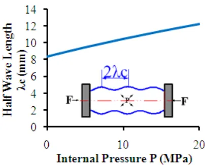
Fig.5- 4 Half wave length from analytical model ... 84
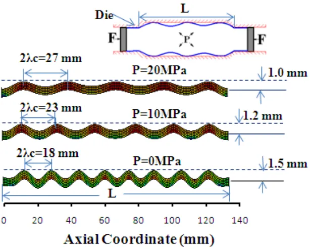
Fig.5- 5 Half wave length from FEA ... 85
Fig.5- 6 Critical strain Vs internal pressure (constant pressure profile) ... 85
Fig.5- 7 Wrinkle development with die constrains ... 86
Fig.5- 8 Wrinkle height from analytical model ... 87
Fig.5- 9 Wrinkle height at 20% compression from FEA ... 88
Fig.5- 10 Wrinkle growth height Vs axial strain at different pressure profile ... 88
Fig.5- 11 Axial stress Vs axial compression under different pressure ... 89
Fig.5- 12 Axial stress Vs axial compression under different pressure ... 89
Fig.5- 13 (a) Non-axisymmetric wrinkle (b) Localized wrinkle [16] ... 90
Fig.5- 15 Two-stage preforming to generate uniform wrinkle ... 92
Fig.5- 16 The end bulge and preforming stage 1 ... 93
Fig.5- 17 Scheme of the process design in the preforming stage and final THF process ... 97
Fig.6- 1 Tube bulging process ... 99
Fig.6- 2 Half wave length λc Vs strain hardening exponent n ... 101
Fig.6- 3 Critical axial strain Vs strain hardening exponent n ... 101
Fig.6- 4 Wrinkle growth height Vs axial compression with different strain hardening exponent n ... 102
Fig.6- 5 Axial response Vs axial compression ... 102
Fig.6- 6 Bulged shape ... 103
Fig.6- 7 Prefoming die and bulging die ... 104
Fig.6- 8 The formed wrinkle during the preforming stage 1 ... 105
Fig.6- 9 Wrinkle growth Vs axial compression at different pressure profile ... 106
Fig.6- 10 Axial stress response at different linear pressure profile ... 106
Fig.6- 11 Wrinkle growing in the preforming stage 2 ... 107
Fig.6- 12 Wrinkle removal and formed part ... 108
Fig.6- 13 Thinning distribution of the bulged part ... 109
Fig.6- 14 Die for direct THF forming ... 109
Fig.6- 15 Directly hydroformed part ... 109
Fig.6- 16 Thinning rate and expansion rate comparison ... 110
Fig.6- 17 Half wave length Vs internal pressure of Al 6061 tube. ... 111
Fig.6- 18 Wrinkle height Hb Vs axial compression at different pressure . ... 111
Fig.6- 19 Axial stress Vs axial compression at different pressure ... 112
Fig.6- 20 Wrinkle evolution and formed part ... 113
Fig.6- 22 Die for direct THF forming ... 114
Fig.6- 23 Directly hydroformed part ... 114
Fig.6- 24 Thinning rate and expansion rate comparison ... 114
Fig.6- 25 Half wave length Vs tube thickness t ... 116
Fig.6- 26 Wrinkle growth height Hb Vs axial compression at different thickness t.. 117
Fig.6- 27 Axial stress Vs axial compression at different thickness ... 117
Fig.6- 28 Half wave length Vs internal pressure ... 118
Fig.6- 29 Wrinkle growth height Vs axial compression under different pressure .... 119
Fig.6- 30 Axial stress Vs axial compression under different pressure ... 119
Fig.6- 31 Wrinkle evolution and formed part ... 120
Fig.6- 32 Thinning rate and expansion rate distribution ... 121
Fig.6- 33 The thinning distribution comparison at different thickness ... 121
Fig.6- 34 (a) Die of preforming 1 (b) Die of preforming 2 (c) Die of final THf process ... 122
Fig.6- 35 Wrinkle evolution and formed part ... 123
Fig.6- 36 Thinning rate and expansion rate distribution ... 124
Fig.6- 37 Preforming and bulging die ... 125
Fig.6- 38 Wrinkle evolution and formed part ... 125
Fig.6- 39 Thinning rate distribution ... 126
Fig.6- 40 Tube used to study the effect of mesh size ... 127
Fig.6- 41 Wrinkle onset with different number of elements in one wave length ... 128
Fig.6- 42 Thinning distribution for different mesh size in one wave length... 129
Fig.7- 1 (a)150-ton hydroforming press (b) Forming die ... 132
Fig.7- 2 Loading path for hydroforming bulge part ... 133
Fig.7- 3 (a) Wrinkle formation in preforming stage (b) Bulged part ... 134
Fig.7- 5 Loading path for hydroforming the part with varying cross section ... 136
Fig.7- 6 (a) Wrinkle formation in preforming stage (b) Formed part ... 137
Fig.7- 7 Sybron thernolyne furnace ... 138
Fig.7- 8 Compressed samples for the flow stress measurement ... 140
Fig.7- 9 Flow stress of annealed Al 6061 ... 141
Fig.7- 10 Loading path of hydroforming the bulge ... 143
Fig.7- 11 (a) Wrinkle formation in preforming stage (b) Bulged part ... 144
Fig.A- 1 Wrinkled tube and it’s size ... 158
Fig.B- 1 Program menu ... 164
Fig.B- 2 Process variables dialogue ... 165
Fig.B- 3 Solution setting dialogue box ... 167
Fig.B- 4 Wrinkle height curve ... 169
Fig.B- 5 Tube axial rigidity curve ... 170
Fig.B- 6 Half wave length at three pressure levels ... 171
Fig.B- 7 Wrinkle number at three pressure levels ... 172
Fig.B- 8 Wrinkle height at three pressure levels ... 172
LIST OF TABLES
Tab.1- 1 Forming problem and solution in the metal forming processes ... 8
Tab.II- 1 Tubular part classification ... 68
Tab.4- 1 Fitted material parameters of SS 304 and Al 6061 ... 74
Tab.5- 1 Geometrical sizes of the SS 304 tube ... 83
Tab.6- 1 Matrix to study the effect of the strain hardening exponent n ... 99
Tab.6- 2 Matrix to study the effect of the tube thickness t ... 99
Tab.6- 3 Matrix to study the effect of the die span length Ls ... 100
Tab.6- 4 Process variables in the preforming stages and final THF process for material SS 304 ... 108
Tab.6- 5 Process variables of preforming and final THF process of Al 6061 tube ... 112
Tab.6- 6 Comparison of the formability of different n ... 115
Tab.6- 7 Process variables of preforming and final THF process for SS 304 tube of thickness 0.8 ... 120
Tab.6- 8 Formability comparison between different SS 304 tube thickness t ... 121
Tab.6- 9 Process variables of preforming and final THF process for Al 6061 tube with die span of 150 mm ... 123
Tab.6- 10 Formability comparison at different die span ... 124
Tab.6- 11 Process parameters of preforming and final THF for varying cross section tube ... 126
Tab.6- 12 Matrix of the tube mesh size ... 127
Tab.7- 1 Experimental data for tube compression test at low strain range ... 139
Tab.7- 3 Material properties of annealed Al 6061tubing based on triple piecewise
LIST OF SYMBOLS
e ,
: effective stress
e ,
: effective strain
Pi (i=a, b, c, d……): preform shape of billet
Xi (i= a, b, c, d……) : deformed shape of the billet
Ls: longitudinal span of the tube hydroforming die cavity
R, t, L: tube radius, tube thickness and tube length
E: Young’s modulus
V: Poisson ratio
σy: yielding stress
n*: plastic hardening parameter
K: strength coefficient
n: strain hardening exponent
σc: critical axial stress of wrinkle onset εc: critical strain
λc: half wave length of wrinkle onset
Δ: axial compression rate
σθ: hoop stress
Nx: axial stress resultant
Nθ: hoop stress resultant
Cij ( i,j=1,2): constitutive matrix element
W0: imperfection factor
w: geometrical imperfection
W: radial displacement
Hb : wrinkle height
p, p1,p2 : internal pressure
f1, f2 : axial feeding
ER: expansion rate
TR: thinning rate
N: wrinkle number
CHAPTER 1: INTRODUCTION
1.1 Introduction
Metal forming is a manufacturing process in which the shape of the desired part is
obtained through the plastic deformation from an initial work piece of simple shape. The
processes involved with the metal forming include rolling, forging, extrusion, drawing,
sheet metal forming, tube hydroforming etc. During the metal forming process, the work
piece experiences severe plastic deformation under the action of the tools and very less or
no material is removed. The parts made from the metal forming process commonly have
better mechanical properties than parts made from casting or machining due to the
change in properties caused by severe plastic deformation.
1.2 Problem statement
In the metal forming process, material flow pattern can be affected by a number of
process variables such as: geometrical complexity, friction conditions, temperature
distributions, stress/strain, velocity gradient and material properties. Improper material
flow pattern can result in forming defects. Therefore, the forming sequence needs to be
carefully designed. Material flow characteristics and the associated forming defects will
be highlighted in the next section for forging, extrusion and tube hydroforming.
Material flow in forging process. During the forging process, the material flow will take
a path of least resistance. It is critical that die and preform shapes are designed in such a
way that they create material flow paths which do not result in defective part. The
Normally, under fill is caused by insufficient starting mass, poor lubrication or improper
material fill patterns. Fig.1-1.b, c and d show the formation of the under-fill defect due to
improper material flow pattern. When a billet is deformed by the finisher die without
preforming, the upsetting-type material flow where material velocity is in the lateral
direction is dominant under the compression stress σn and friction stress τf of the dies.
Under this scenario, once the lateral material flow hits the die corner, the material flow is
split into two, one becomes extrusion-type material flow which has a velocity field V1
toward the rib top, and another keeps the original direction and has a velocity field V2.
Because of the excessive amount of material flow in the lateral direction, considerable
amount of flash is formed, while insufficient material fill in the rib part results in the
under-fill defect as shown in Fig.1-1d. The ideal flow pattern for avoiding under fill is
the dominant extrusion-type material flow in the rib region, which can be realized by
introducing a preformed billet shape (Fig.1-1e) to promote the material flow in the rib
Fig.1- 1 Under fill in forging process and preform
Lap is material folding over a metal surface and is not metallurgically bonded together
due to an oxide layer. Lap defects are usually formed due to improper progression of
material flow in the die cavity. Fig.1-2 a,b shows a typical process of the lap formation.
Due to the filling velocity gradient from the left side to the right side of the die cavity,
the left side of the die cavity accumulates more material. Therefore, the left-side material
hits the top of the cavity first and then bounces backwards to form a material flow (V2)
reversal to the right filling material (V1). Because of the reversal material movement,
material is folding over the metal surface and forms the lap as shown in Fig.1-2.b. The
ideal material flow pattern for avoiding the lap formation is the proper progression of the
material fill in the die cavity as shown in the Fig.1-2.c, which can be realized by a good
Fig.1- 2 Folding defect
In the forging of the web-rib (Fig.1-3a) part, the piping defect is also associated with the
material flow pattern. When the upper die moves downwards, the material on the web
region is compressed and flows into the rib region, which forms an extrusion-type
material flow. During the advancing, both sides of the material flow are subject to the
contact pressure σn and friction stress τf , resulting in a center-to-surface velocity
gradient (V0 to V1 in Fig.1-3b) which draws more material from the web center to form a
dimple on the opposite face. The piping defect can be eliminated by increasing the web
thickness t or changing the aspect ratio (H/B). If both methods could not be done, a
preformed protrusion shown in Fig.1-3.c can be used to counteract the extra material fill
Fig.1- 3 Piping defect in the rib-web part forging
Other than the material flow associated defects, fracture may occur when the material
experiences high effective strain and work hardening conditions. Under this circumstance,
annealing is needed to remove the work hardening.
Material flow in extrusion process. In the extrusion process, the billet is pushed by the
ram to pass through a die opening to realize section changing (Fig.1-4.a). When the
material flows through the die opening, a dead zone of stagnant material flow will build
up at the die corner due to friction force from the die. The dead zone acts as a rigid die
surface and the material undergoes shear deformation along the interface of the dead
zone. The size of the dead zone can be affected by the temperature gradient, punch speed,
friction condition and extrusion ratio. Fig.1-4.b,c,d show three different material flow
patterns at different friction conditions and temperature gradient. An ideal pattern
without dead zone (Fig.1-4 b) can be observed with frictionless conditions at the
container and die. The material properties of the extruded part are uniform in the
longitudinal direction and transverse direction. When friction force is presented on the
die and container surface, flow pattern with dead zone (Fig.1-4 c) can be found near the
die surface. The material near the dead zone surface moves diagonally to the exit at
slower velocity than the material at the center, forming the outer shell of the extruded
When the temperature gradient or inhomogeneous material properties is presented on the
billet from center to surface, a flow pattern with more severe shear deformation and
extended dead zone will develop as shown in Fig.1-4.d. This flow pattern will result in
unacceptable gradient of the material properties on the extruded part. Normally, extra
preforming stage or heat treatment is required to overcome these forming defects.
Fig.1- 4 Three types of flow patterns in the extrusion process
Material flow in the tube hydroforming process. Tube Hydroforming (THF) is the metal
forming process that uses a pressurized fluid in place of a hard tooling to plastically
deform a tube into a desired part, which offers advantages such as: part consolidation,
stiffness over parts made by conventional stamping-weld technology. In the THF process,
accurate material feed and internal pressure profile known as loading path is critical to
avoid forming defects, such as buckling and fracture.
During the expansion of the tube, the material is subject to severe interface friction
(Fig.1-5.b) due to high internal pressure. The interface friction hinders material from
flowing into the die cavity and reduces the uniformness of the thinning distribution.
When material is pushed to die cavity under internal pressure, the tube is subject to
biaxial-tensile stress, which tends to make the tube thin out and burst. If the tube has
axial compressive stress and circumferential tensile stress (Fig.1-5.c), the thinning due to
hoop tensile stress can be compensated by axial compression deformation and higher
expansion can be achieved.
Fig.1- 5 THF process and preform
Depending on the shape complexity and formability of the material, the incoming
straight tube may need to be preformed, such as pre-bending, crushing prior to the final
Tube Hydroforming process. The pre-bending process is mostly used to bend the straight
often used to deform the tubes in such a way that a certain amount of material can be
accumulated in the large expansion zone of the final THF process to avoid excessive
thinning and bursting. However, how to preform the tube to accumulate material in the
forming zone is still a very challenging task.
From the above discussions, the forming defects associated with material flow and it’s
possible solutions are identified in three metal forming processes. They are summarized
and listed in the Tab.1-1 below.
Tab.1- 1 Forming problem and solution in the metal forming processes
Forming problems Metal forming process
Solutions
1 Under fill Forging Proper material fill sequence Or preform shape design
2 Laps Forging Proper progression of material flow
or preform shape design
3 Piping Forging Optimization of the rib parameter
or add preforming step
4 Fracture/Excessive work hardening
Forging Heat treatment
5 Dead zone Extrusion Minimize the friction or reduce the temperature gradient
6 Inhomogeneous material properties
Extrusion Minimize the friction or reduce the temperature gradient
7 Severe friction
condition
Tube Hydroforming Developing better lubricant
8 Thinning/Fracture Tube Hydroforming Proper preforming design
1.3 Research objectives
The main goal of this research is to develop a preform design methodology or preforming
process to avoid the forming defects associated with the material flow and improve the
formability of the forging and tube hydroforming processes.
The specific objectives pertaining to forging are:
a) Develop a preforming design methodology for the forging and extrusion processes
b) Verify the developed method by carrying out the FEA simulations for several cases.
c) Verify the developed method experimentally.
The specific objectives pertaining to tube hydroforming are
a) Model wrinkle formation in the Tube Hydroforming process
b) Develop preform design methodology for THF based on wrinkle generation
c) Study the effects of process variables on formability for THF with wrinkle based
preforming.
CHAPTER 2: LITERATURE REVIEW
2.1 Preform design for forging process
2.1.1 Forging process and operations
Various forging parts usually have complex geometrical shapes which need intermediate
passes to forge a sound part due to material flow limitation. In a common multistage
process, a set of blocking dies are used to sequentially preform the initial billet into a
proper shape suitable for the finisher forging. If the material of the billet could not be
distributed properly in the blocking stage, forming defects such as under fill, laps and
folding would occur in the final forging stage.
Normally, the forging-sequence design is carried out in a backward direction (Fig.2-1),
which starts with the finished-part geometry and ends up with the preform shape design,
die design and process parameters determination. During each phase of the process
design, all the physics involved in the metal forming process such as plastic deformation,
heat transfer, lubricant& interface friction, and microstructure evolutions need to be fully
considered to determine the preform shape, forging equipment and die configuration. The
overall design of the forging process requires (1) prediction of the preforming numbers
(2) determination of the preform shape (3) determination and optimization of the process
Fig.2- 1 Complex physics and forming sequence of the forging process
2.1.2 Preform design and optimization
In the forging industry, design of die performs has heavily relied on tryout, accumulated
experience, and skill of the process designers. In the last few decades, expert-systems
[1–14] based preform design methods have been developed in metal forming process to
facilitate the forging process design. Most expert systems developed for determining
forging sequences for cold- and hot-forged parts make use of rules and/or known
progression sequences that can be retrieved from a database. For example, Kim and Im [5]
developed an expert system that can produce the basic process design depending on the
initial billet size, the material, or the order of upsetting and forwards extrusion. This
system was also capable of process redesign based on either reduction of number of
distribution and the level of the required forging load by controlling the forming ratios.
Bakhshi-Jooybari et al. [14] proposed an intelligent knowledge-based system for
designing dies and forging processes, whereby the system compares new forging parts
with those it had encountered previously. The comparison was based on weighting
effects of process and geometrical parameters that significantly influence the success of
the forging.
Owing to a multitude of variables involved in a forging operation, there may exist
different forging sequences to produce a sound part. This may involve changing
parameters such as the initial diameter of the billet or the intermediate forging
progression steps, e.g. upsetting, forwards extrusion, or backwards extrusion. Kim and
Im [11] proposed a search method to determine an optimal process sequence using the
controlled variables of global effective strain and required forging load at each stage. In
this expert system, the search was carried out after a tree of possible process sequences
was established.
Because the expert systems are rule-based and use plasticity theories, empirical formulae,
approximate load calculations, etc. an optimal forging sequence that will lead to a sound
part may be hard to obtain, particularly if the forged part is complicated. For this
situation, expert systems have widely been used to provide initial progression sequences
of forging, which are later refined to ensure good material flow, complete die fill, and
that other part defects associated with material flow are eliminated. Several researchers
have incorporated finite element analysis (FEA) in expert systems as a verification tool
for the established forging sequences [3, 4].
Much effort has been directed towards direct use of FEA in determining forging
sequences, particularly for parts that require few progression sequences. Park et al.
proposed a backwards tracing method in preform design of shell nosing [15]. In 1989,
design in forging processes based on rigid visco-plastic finite element methods [16]. The
preform shape can be computed by detaching boundary nodes from the die contact in an
assumed sequence or based on some criterion. The method was successfully applied to
the preform design of an axisymmetrical H-shaped forged part [17]. However, the
validity of backwards tracing highly depends on the node-detach criteria for the
deformation path. Zhao et al. [18, 19] proposed two detach criteria based on contact
history and shape complexity. The detach criteria were, however, limited to specific
forging parts. Chang and Bramley [20] proposed a methodology for detaching contact
areas from the die surface by combining the upper-bound method with the finite-element
(FE) procedure. The premise of this detach criterion was that during forwards simulation,
the contact areas between work piece and dies increase along the cavities. This
contacting sequence can thus be inverted in reverse simulation, i.e. nodes are detached
along cavities from the deepest area. Although this method was successfully employed
on a plane-strain problem, it was difficult to obtain smooth boundary shape via the FE
procedures.
Researchers have attempted to optimize forging preforms by using sensitivity analysis.
The objective function in the sensitivity analysis is to minimize under-fill, eliminate
barreling, or decrease the deviation of the state variables, whereas the design variables
are coordinates of the control points of shape edges. Badrinarayanan and Zabaras
developed a sensitivity analysis for large deformation of hyper-elastic visco-plastic solids
for optimization of extrusion die shape to achieve a more uniform distribution of the state
variables on the extruded part [21]. Fourment and Chenot suggested a shape optimization
method for the initial shape of the billet as well as the shape of preform die of a two-step
forging operation [22]. Zhao et al. optimized the die preform shape to minimize the
difference between actual forging shape and the desired final forging shape, based on
sensitivity analysis [23]. Srikanth and Zabaras optimized the shape of the initial billet to
problem [24]. Zabaras et al. developed a sensitivity method to optimize the die preform
shape for multi-stage metal-forming processes [25]. Vieilledent and Fourment proposed
that folding defects could be avoided by minimizing the sum of the effective strain rates
on the surface of the work piece [26]. Castro et al. adopted the direct differentiation
method to obtain sensitivity information in preform optimization design of a two-step
forging process [27].
Preform optimization based on sensitivity analysis is an efficient algorithm to find a
optimal preform shape, but it requires gradient information of the objective function with
respect to the design variables. Depending on the complexity of the problem, obtaining
gradient information may be difficult and several non-gradient-based preform
optimizations have been proposed to avoid using gradient information. Castro et al.
adopted a genetic algorithm to eliminate the barreling in the hot-forging process [28].
Thiyagarajan and Grandhi proposed an optimization algorithm for a three-dimensional
(3D) preform shape design based on the response surface method, in which the preform
shape was treated as a linear combination of various billet shapes called basis shapes,
where the weights for each basis shape were used as design variables [29]. Hong et al.
suggested an iterative preform design method to reduce flash formation and forging load.
The optimal preform shape was found by iteratively mapping the shape of the formed
flash of reduced size to the initial billet shape [30].
Due to various combinations of the forging processes and complexity of the plastic
deformation, most preform design methods are specifically limited to certain processes
and the prediction of the preforming number and obtaining of the preform shape is still a
difficult and time-consuming task during the forging process design, which needs further
2.2 Preforming for tube hydroforming process
2.2.1 Tube hydroforming system
In recent years, the tube hydro-forming (THF) process has received increased attention in
the automotive and aerospace industries owing to its numerous advantages over stamped
and welded assemblies. The advantages of THF include part consolidation, weight
reduction, higher part quality, fewer secondary operations, reduced dimensional
variations, and improved structural strength and stiffness. However, this process has also
some drawbacks, such as slow cycle time, expensive equipment and lack of extensive
knowledge base for process and tool design, which leads to appearance of defects in the
hydro-formed part [34].
A typical Hydroforming process is the T-shape joint forming processes as shown in
Fig.2-2. Firstly, a straight tube is properly positioned in the die which has the same shape
as the desired part (Fig.2-2.a). Then the die is closed by the ram of the press and the axial
cylinder drives the punch to contact the tube end tightly without leakage (Fig.2-2.b).
After die closing and complete sealing, the forming oil is pumped into the tube cavity
and pressurized, while the axial punch compresses the tube axially and the counter punch
retracts gradually to support the protrusion part (Fig.2-2.c). Finally, the formed T-shape
Fig.2- 2 Typical tube hydroforming process
Depending on the shape complexity of the tubular part and formability of the tubular
material, the incoming straight tube may need to be preformed, such as pre-bending,
crushing. The pre-bending process is mostly used to bend the straight tube to curved
longitudinal configuration to fit the final THF die cavity, which significantly deviates
from the straight tube. Tube crushing is used to deform the tube in advance to avoid
collision with the die during die closing, or to accumulate materials in the forming zone,
if the part has cross section of complex shape or big expansion rate. Besides the careful
determination of the process sequence, process variables such as loading path, friction
condition and material properties play a critical role in the process design of the THF
process. The influence of these process variables will be briefly discussed next.
The most concerned process variable in THF is the proper matching of the
hydro-forming pressure with axial feeding. Tube failure is evident when excessive axial
feeding results in wrinkling, whereas too much internal pressure leads to tube bursting. In
the last decade, a number of algorithms such as sensitivity analysis, response surface
development to avoid the forming failure.
The quality and properties of the tubular material can highly affect the THF process.
Fuchizawa [40-41] investigated the effect of the strain-hardening exponent and plastic
anisotropy on the THF process. The study showed that more uniform thickness
distribution, greater expansion, and less hydro-forming pressure can be achieved by
increasing the strain-hardening exponent while the plastic anisotropy can affect internal
pressure requirement or the maximum expansion of the tube. Thus the material properties
(elasticity modulus, yield stress, ultimate tensile strength, ductility, and anisotropy)
should be determined carefully for THF process to form the part with desired quality.
Currently, the tubular bulge test has been widely used to determine the properties of
tubular materials due to the similar stress conditions with the actual THF process and
greater effective strain achieved [42].
The friction control and lubrication play a key role in the THF process, because the
friction can highly influence the thinning distribution, surface integrity, forming load,
and tool wearing. In the THF process, the actual friction coefficient is a function of
contact pressure, sliding velocity, sliding distance, material properties and surface
roughness of the surfaces in contact. During the THF process, the friction condition
changes due to variation of the actual tribological variables mentioned above. Thus, the
friction coefficient is not constant with respect to the process time. Depending on the
different deformation mechanism, three friction zones are identified in THF: guiding
zone, transition zone and expansion zone. Accordingly, experimental tests [43-44] have
been developed to mimic the friction characteristics in the respective zones to evaluate
the lubricant performance in the THF process.
The influence of the process variables on the tube Hydroforming are briefly reviewed
above and the major issues need to be considered in the tube Hydroforming process
a) Tube Material properties and quality
b) Pre-forming design (bending, crushing) and post- forming (punching, trimming)
operations
c) Loading path determination and optimization
d) Design of dies and tools
e) Friction condition evaluation and lubricant development
2.2.2 Preforming for tube hydroforming process
During the hydro-forming of a long tubular part of complex cross section, the axial
feeding provides limited material flows and the pure expansion occurs at some middle
part of the tube due to the geometrical constrain or friction conditions. In this case, the
crushing operations are used to deform the tubes in advance and accumulate a certain
amount of material in the large expansion zone of the final THF process to avoid
excessive thinning. There are two types of crushing operations, one is crushing the
larger-diameter tube in the radial direction to accumulate material, and another is
crushing the tube in the axial direction to accumulate the material.
2.2.2.1 Preforming by crushing tube in the radial direction.
Normally, a radial crushing operation is needed to deform a big tube (Fig.2-3.b), having
close circumferential length with the final part, to a preformed shape to fit the final THF
die, if the tubular part has a complicated cross section shape with the aspect ratio
significantly deviating from the round shape (Fig.2-3.c). Sometimes, a lower internal
pressure is applied in the radial crushing operation to avoid folding or excessive hoop
wrinkle. If the tubular part is directly hydro-formed with a small tube (Fig.2-3.a), the
expansion rate is too high and tube will burst during the direct hydroforming. Actually,
the radial crushing operation can reserve significant amount of material in the forming
used to deform a tube to a shape to fit the final THF die and avoid the pinching (Fig.2-4)
of the tube during the die closing. In some cases, the radial crushing and final THF are
fused into a single process to reduce the process stage and save production cost. Next,
two cases of the radial crushing will be illustrated.
Fig.2- 3 Radial crushing operation for the cross section Hydroforming
Fig.2- 4 Pinching of the tube during die closing
Hwang et al,. [45] hydroformed a large-size tube into square-cross section in a process
fusion of the crushing and THF process (Fig.2-5). He found that thickness the
expansion, whereas the internal pressure and crushing force are significantly less than
that of direct expansion.
Fig.2- 5 Process fusion of the crushing and THF to form the square cross section.[45]
A lower arm of the suspension component is hydro-formed to substitute the traditional
stamp-weld part by combined processes of the prebending, crushing and THF [46]. Due
to the limited material flow in the middle part of the lower arm, a larger-diameter
tube ,which is bigger than the minimum cross section of the lower arm, is initially
prebent to fit the die(Fig.2-6.a), then it is radially crushed to reduce the cross section
size(Fig.2-6.b) and finally Hydro-formed by higher pressure and axial feeding
Fig.2- 6 Multip-stage tube hydroforming process [46]
2.2.2.2 Preforming by crushing tube in the axial direction.
Besides the radial crushing, the longitudinal crushing is also an effective measure to
accumulate the material in the form of axisymmetric wrinkle formation (Fig.2-7) in the
forming zone. Normally, the wrinkle formation due to the excessive axial feeding should
be avoided during the hydro-forming process and the forming window without wrinkle is
the zone ABCDE as shown in Fig.2-7.c. However, if the wrinkle formed during the
process can be flattened by the higher pressure at the end of the process, the forming
window ABCDE can be expanded to AB’CDE and the formability of the THF process
Fig.2- 7 Axial crushing and expanded forming window
In the conventional tube hydroforming process, the wrinkle is considered as failure and
should be avoided. Therefore, most researches are working to develop accurate loading
path to avoid wrinkle and bursting. But the research on how to use the wrinkle formation
to expand the forming window is still limited. Yuan and his colleagues [47-48] initially
investigated the effect of the wrinkle behavior in the tube bulging process and found that
the wrinkle formed in the tube bulging process can be classified into three types, i.e.
useful wrinkles, dead wrinkles and bursting wrinkles. The useful wrinkle can serve as
The expansion rate of the Aluminum-alloy A502 tube reached 34% (Fig.2-8) with useful
wrinkles compared with 10% expansion rate of the bulging process without wrinkle. A
method based on the geometrical condition [48] was developed to estimate the axial
feeding amount and thinning rate for the bulging process with useful wrinkles. Lang et
al., [49] investigated the influence of the die cavity shape of the preforming process on
wrinkle development and found that the die of 25-degree taper angle is more favorable
than the die of 45-degree tape angle to form useful wrinkles in the multiple stage bulging
process. Wang et al.,[50], hydro-formed an unsymmetric tubular part by using the useful
wrinkles to accumulate material in the forming zone.
Fig.2- 8 The bulging process with useful wrinkle of Aluminum Alloy tube [47]
From the discussions above, the wrinkle formation can improve the formability of the
THF process if the wrinkle is removable. The same observation is also found in the tube
Hydroforming process with pressure pulsation. A loading path with pressure oscillation
[51] was used to hydro-form a bugle-shape without bursting, while the one without
pressure oscillation bursts (Fig.2-9). The mechanism of the formability improvement by
the pressure pulsation is investigated by K. Mori and his colleagues,[52]. It was found
that formability improvement due to oscillating pressure is associated with repeated
small wrinkling (Fig.2-10) and the amplitude of the pressure oscillation has greater
effects on the formability improvement than the frequency. Hama et al.,[53], simulated
the hydro-forming process of the automotive component (Fig.2-11.a) with internal
and shows that the lower friction coefficient roughly has the same effects as the pressure
pulsation to improve the expansion on the automotive component. M.Loh-Mousavi et
al.,[54], simulated the Hydroforming process of the T-shape with pressure pulsation and
the same result as that in [20] was found.
Fig.2- 9 Formability improvement of tubular part by pressure pulsating in THF[51]
Fig.2- 11 (a) Automotive component (b) Loading path with pressure pulsation [53]
In summary, the removable wrinkle in the THF process can improve the formability of
the tube. In general, two types of initial loading paths can be used to form wrinkles, one
is the lower pressure with high axial feed, another is the pressure pulsation. Both types of
loading paths end up with higher pressure to remove the wrinkle or calibrate the final
shape. Yuan and his colleges initially used the wrinkle formation in the bulging process
of Aluminum alloy tubes, and a method based on geometrical condition is developed to
estimate the axial feed amount and average thinning rate of the bulged tube. However,
how the wrinkle develops and how the process variables such as material properties,
geometrical size and loading path affect the wrinkle characteristics are still not clear.
These two issues are critical for the axial crushing operations and need further research
efforts.
2.2.3 Wrinkle formation theory for tube under axial compression
As discussed previously, the formability improvement in the THF process can be
achieved by the proper material accumulation in the forming zone by radial crushing or
longitudinal crushing. The wrinkle formation characteristics in the longitudinal crushing
of the tube can be affected by the loading path (internal pressure Vs axial feed), die
understand the plastic wrinkle evolution for the better design of the axial crushing
process. In the last half century, a number of analytical models of plastic wrinkles have
been developed to understand the wrinkle evolution characteristics in the structure design.
Hills theory [55] of bifurcation analysis of elastic-plastic solids laid down the basis for
the critical condition analysis of plastic wrinkle onset. The bifurcation analysis of the
plastic wrinkle onset based on the “J2 deformation theory” [56] generally yields much
better agreement with experiment than that of “J2 flow theory” [57]. Tvergaard [58]
investigated the influence of various geometric and material parameters on the
elastic-plastic wrinkle of cylindrical shells based on “J2-flow”, “J2-deformation” and
“J2-corner” theories. He found that the general tendency is that “J2 corner theory”
predicts a buckling load higher than that of “J2 deformation theory”, but lower than that
of “J2 flow theory”.
2.2.3.1 J2 deformation theory
It was commonly known that the relationship between the stress tensor (ij) and
deviatoric stress (Sij) can be given by equation (2-1) [62].
ij ij
1
S =
-3
kk ij
(2-1)
Three invariant J1, J2 and J3 of the deviatoric stress Sij can be expressed by the following
equations.
1
2 2 2
2 1 2 2
3 1 2 3
0
1
1
(
)
2
2
1
det
3
kk ij ijij jk ki
J
S
J
S S
S
S
S
J
S
S S S
S S S
Where S1, S2 and S3 are principle stresses of deviatoric stress tensor Sij. It was postulated
by Von Mises that materials will yield once the second invariant J2 reaches a critical
value. The yielding criterion can be written in the form of equation (2-3). The criterion
leads to a circular cylindrical surface in the (σ1, σ2, σ3) space.
2 2 2 2
2 1 2 2 3 3 1
1
(
)
(
)
(
)
6
J
k
(2-3)
Assuming the yielding surface is Mises type represented by equation (2-3), the
equivalent stress can be defined as follows,
1/ 2 2 2 2
2 1 2 2 3 3 1
3
2
3 ( ) (
)
(
)
(
)
(
)
2
2
e
J s
ijS S
(2-4)
Once the material yields, the plastic deformation occurs. There were two kinds of
theories used to model the plastic deformation process. One is “J2 deformation theory”
and another is “J2 flow theory”. The “deformation theory” was developed by Henky and
Nadai to analyze the plastic deformation problem with total stress-strain relationship. In
deformation theory, the plastic strain components are proportional to the deviatoric stress
components, with the scalar function of proportionality depending strictly on J2 as
follows:
2
( )
p
ij
g J S
ij
(2-5)
The function g(J2) can be determined through the uniaxial tensile test. Furthermore, the
equation (2-5) can be transformed to equation (2-6) after the function g(J2) is calibrated
by uniaxial test.
3
1
1
[
]
2
( )
For the purpose of measuring the plastic deformation, equivalent plastic strain is defined
as equation (2-7).
1/ 2
2
(
)
3
p p p
e
(2-7)By adding the elastic strain component from Hooks law, the relationship between the
total strain and stress can be modeled as:
1
3 1
1
[
]
2
1
1
1
,
[
]
2
2
ij ij kk ij ij
s
s s s
ij ij kk ij s
v
v
S
E
E
E
E
v
v
E
v
v
E
E
E
(2-8)The rate form of the equation (2-8) is given as follows:
1
3 1
1
9 1
1
(1
)
(
)
(
)
2
4
ij ij kk ij ij ij
s t s e
s d
d
v d
vd
ds
S
E
E
E
E
E
(2-9)For the plane stress condition without in plane shearing deformation, the rate form of J2
deformation theory can be further reduced to equation (2-10).
2
2
1 (2 ) (2 )(2 )
1
(2 )(2 ) 1 (2 )
x x s x x x
s s x x x
d q v q d
d E v q q d
(2-10)
Where: 2
1 1 ( ) 2 2 1 ( 1) 4 e s e s s s e t E E v v E E q E
mathematic manipulation and the derivation of closed-form solutions for several practical
problems.
2.2.3.2 J2 flow theory
The nature of the plastic deformation is path dependent, which could not be fully
characterized by the total stress-strain relationship. Thus, the incremental relationship
between the stress and strain is required in formulation of the plastic deformation
problem. In the J2 flow theory, the components of plastic strain increment is normal to
the yielding surface and are linearly proportional to the components of stress increment
as shown in equation (2-11) [62].
1
(
)
p ij mn mn ijf
f
d
d
H
(2-11)Where f is the current yielding surface (equation (2-3)), and H is a scalar function of
stress and of the loading history. A scalar measurement of plastic strain increment is
called equivalent plastic strain increment which is defined as follows,
1/ 2
2
(
)
3
p p p
e
d
d
d
(2-12)The total equivalent plastic strain can be obtained by summing all increments of
equivalent plastic strain as equation (2-13):
p
p
e
d
e
(2-13)Substituting yielding function 2-4 into equation 2-11, incremental stress-strain
2
1
9
(
) ,
4
p
ij ij p
e e
d e
d
S d
S H
H
d
(2-14)By adding the incremental elastic strain from Hooks law, the model can be completed as:
1
(1
)
9 (
)
ij i j kk ij ij
d
v d
vd
Q s d
S
E
(2-15)
For the plane stress condition without in-plane shearing deformation, equation 2-15 can
be expressed as:
2
2
1
(2
)
(2
)(2
)
1
(2
)(2
)
1
(2
)
x x x x x
x x x
d
Q
v Q
d
d
E
v
q
Q
d
(2-16)Where: 2
1
(
1)
4
e tE
Q
E
2.2.3.3 Wrinkle onset
Considering an axially loaded circular cylindrical shell shown in Fig.2-12, the nonlinear
equilibrium equations for axisymmetric deformations of such a shell can be given as
equation 2-17.[62]
' 0
'' '' 0
xx
xx
xx R t
N
N
w
Fig.2- 12 Wrinkled tube and it’s size
Where Nxx , Mxx, Nθθ and σxx are axial stress resultant, axial bending moment, hoop
stress resultant and axial stress respectively. The kinematical equation [62] of the shell
can be expressed as:
0 0 , , x xx xx xx R
u
w
w
(2-18)The buckling mode satisfies the equilibrium equation (2-18) has the form as:
cos(
)
sin(
)
x
w a
x
u b
(2-19)By substituting (2-18), (2-19) into equilibrium equation (2-17) and using the constitutive