ABSTRACT
ARCHER, JOHN RICHARD. Multi-objective Design Optimization of a Variable Geometry Spray Fuel Injector. (Under the direction of Gregory D. Buckner.)
Multi-objective Design Optimization of a Variable Geometry Spray Fuel Injector
by
John Richard Archer
A thesis submitted to the Graduate Faculty of North Carolina State University
in partial fulfillment of the requirements for the degree of
Master of Science
Mechanical Engineering
Raleigh, North Carolina 2013
APPROVED BY:
_______________________________ ______________________________
Scott M. Ferguson Gary W. Howell
DEDICATION
BIOGRAPHY
ACKNOWLEDGMENTS A number of people provided a valuable support on this project:
My adviser, Dr. Buckner, has spent more hours on this project than anyone besides myself, and his guidance shaped it from the original concept through the final edits. I will always be grateful for the time he spent teaching me to write and present information more effectively.
The members of my committee were always generous with their time and ideas throughout this research. Each provided valuable ideas and advice in their own areas of expertise. I am grateful to the National Science Foundation for funding my work on this project through the Combustion, Fire, and Plasma Systems program.
All of the researchers in the EMRL helped in various ways throughout the process. J.P. Lien helped me get going as I picked up this project. Casey Haigh always let me bounce ideas off him and Andy Richards was a great source of information through the process. Shaphan Jernigan always helped me find what I needed in the lab.
Skip Richardson did an awesome job building the prototypes and making modifications to overcome unforeseen problems.
Priyesh Sharma of Dr. Fang’s lab was very accommodating and helpful as we shared the
same experimental setup.
I want to thank my friends, family, and especially my parents John and Lisa Archer, who provided endless moral support through the ups and downs of the research process.
TABLE OF CONTENTS
LIST OF TABLES ... vi
LIST OF FIGURES ... vii
1 INTRODUCTION... 1
1.1 Combustion Background ... 3
1.2 VGS Prototype Development ... 4
2 METHODS ... 11
2.1 Computational Fluid Dynamics ... 11
2.2 Multi-objective genetic algorithms ... 17
2.2.1 Objective functions ... 20
2.2.1.1 Actuator stroke ... 20
2.2.1.2 Spray angle sensitivity ... 21
2.2.2 Optimization Problem ... 22
2.3 Design Parameters ... 22
2.4 Parallelizing CFD Analysis ... 24
3 RESULTS ... 27
4 CONCLUSION ... 32
LIST OF TABLES
Table 1.1 Optimized design parameters and objective functions for Design 1,
Design 2, and the second generation prototype (Prototype 2) ... 29
Table 1.2 Correlation coefficients (ρ) between the design parameters and the
LIST OF FIGURES
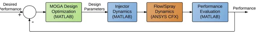
Figure 1.1 Simulation-based design strategy for VGS fuel injector ... 2
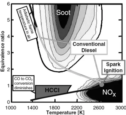
Figure 1.2 Plot of equivalence ratio vs. temperature of combustion, illustrating regions of soot and NOx formation. Regions corresponding to conventional diesel, spark ignition, and HCCI combustion are highlighted. Adapted from [3] ... 3
Figure 1.3 VGS fuel injection for optimized combustion: spray angle variation during engine cycle to ensure targeting of piston bowl and avoid liner wetting and fuel impingement ... 5
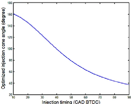
Figure 1.4 Optimal included spray angle as a function of injection timing [11] ... 5
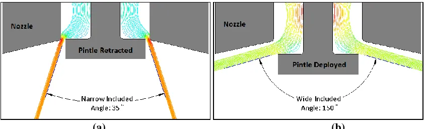
Figure 1.5 2D simulation results of the VGS fuel injection concept: (a) when the pintle is fully retracted, the fuel spray cone has a narrow included angle; (b) when the pintle is fully deployed, it redirects fuel flow to a significantly wider included angle ... 6
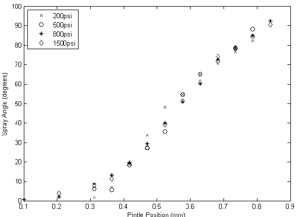
Figure 1.6 Experimental results from manually actuated VGS prototype demonstrating
dependence of included spray angle on pintle position ... 7
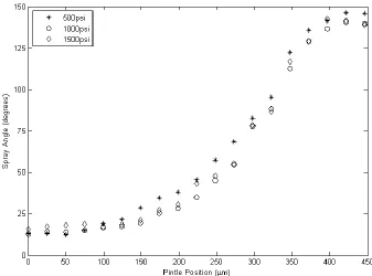
Figure 1.7 Experimental results from second generation prototype demonstrating increased range of included spray angles with decreased pintle displacement ... 8
Figure 1.8 Solid model cross-section of third generation VGS prototype, showing annular nozzle needle for regulation of flow ... 10
Figure 1.9 Representative cross section of a traditional common rail diesel injector in its deactivated state, where the nozzle needle 36 blocks the injection holes 46 [17] .
10
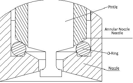
Figure 1.10 Cross section of the distal portion of the third-generation VGS prototype,
showing the annular nozzle needle pressed against the O-ring to block flow ... 11
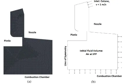
Figure 2.1 2D axisymmetric model of the fuel flow domain for a candidate VGS design showing: (a) an unstructured triangular mesh and (b) boundary conditions and domain initialization ... 13 Figure 2.2 CFD results for a candidate VGS design, showing the locations of , and
, ... 14 Figure 2.3 Dependence of CFD convergence time and spray angle error on mesh element
size, showing the inherent tradeoff between computational efficiency and
simulation accuracy ... 15
Figure 2.4 Nonlinear regression (hyperbolic tangent) of CFD simulation results (nine different pintle positions) showing dependence of spray angle on pintle position ..
16
Figure 2.5 Experimental validation of CFD model by comparing CFD results to empirical spray tests for the second generation prototype ... 17
Figure 2.7 The 15 VGS design parameters that fully define the nozzle (left) and the pintle (right) ... 23
Figure 2.8 The six VGS design variables with the most significant influence on included spray angle, as determined by preliminary CFD analyses: for the nozzle (left)
and pintle (right) 23
Figure 2.9 Flow chart for the design evaluation process using the HPC (colors indicate
which system performed each task ... 26
Figure 2.10 Gantt chart for design evaluation process emphasizing timing and
parallelization (colors distinguish between tasks) ... 26
Figure 3.1 The VGS performance space; design point shading indicates generation number (light shades: early generations, dark shades: later generations), demonstrating convergence of the MOGA and resulting Pareto frontier. Red curve represents theoretical performance limit ... 28
Figure 3.2 The VGS performance space highlighting the final Pareto frontier and the second generation prototype, with extreme VGS designs annotated as Design 1 and Design 2 ... 28
Figure 3.3 The design variables (VGS geometries) for (a) the second generation prototype, (b) Design 1, and (c) Design 2, showing how the design parameters varied in
the optimization ... 30
1 INTRODUCTION
The design, fabrication, and experimental evaluation of sophisticated electromechanical systems can be a time-consuming and expensive process. Inherent non-linearities (flux saturation, flux hysteresis, hardening springs, etc.) necessitate the need for an iterative design and fabrication approach. Optimizing the design of such systems, which may have large numbers of critical design parameters and multiple conflicting performance objectives, can significantly hinder the development and commercialization of innovative technologies. This is particularly true in academic research environments, where facilities and financial resources are limited.
One such technology, variable-geometry spray (VGS) fuel injection, has the potential to significantly improve the efficiency of internal combustion engines while simultaneously reducing emissions. This patent-pending technology enables independent control of fuel flow rate and spray geometry as it enters the combustion chamber. By optimizing air-fuel mixing and the distribution of atomized fuel within the cylinder, VGS injection has the potential to enable combustion at peak efficiency, maximizing power output.
The goal of this research was to develop and demonstrate a unique, simulation-based design optimization strategy for a sophisticated electromechanical system: a hollow-cone VGS fuel injector for diesel IC engines. A multiple-objective genetic algorithm (MOGA) was employed to efficiently and thoroughly explore the design space. The MOGA was interfaced to state-of-the-art computational tools, enabling complete performance evaluations in a simulated environment, dramatically enhancing the efficiency of the design process (Fig. 1.1).
Figure 1.1: Simulation-based design strategy for VGS fuel injector
While the use of computational tools in the design process is not new, this combination of MOGAs interfaced to commercial multi-physics simulators to optimize the design of an inherently nonlinear electromechanical system is innovative. Despite its focus on VGS fuel injection technology, this novel simulation-based design strategy is applicable to a wide range of electromechanical systems, and could enable more efficient and flexible commercialization of innovative technologies.
1.1 Combustion Background
Protection Agency [1] has set maximum levels for particulate matter (PM, or soot) and nitrogen oxides (NOx). It is very difficult to meet these requirements using conventional
diesel combustion methods. Simultaneous improvements in both of these emissions products have been limited due to the fundamental PM-NOx tradeoff shown in Fig. 1.2 [2]. In
conventional diesel combustion, the reactants are only partially premixed, therefore many reactions take place in fuel-rich regions. Such regions give rise to soot particles due to the scarcity of oxygen. PM can be reduced by increasing combustion temperature in order to promote soot oxidization. However, higher temperatures increase dissociation of diatomic nitrogen (N2 → 2N) resulting in increased formation of NOx.
Figure 1.2: Plot of equivalence ratio vs. temperature of combustion, illustrating regions of soot and NOx formation. Regions corresponding to conventional diesel, spark ignition, and HCCI combustion are highlighted. Adapted from [3]
a wider range of fuel richness by lowering combustion temperatures (Fig. 1.2). HCCI does this by combining premixed charge (as in spark-ignition engines) with the compression ignition of diesel engines [4]. Despite the surge of HCCI research and development, feasible implementations in diesel engines have yet to be realized. Currently HCCI must use a lean mixture to minimize soot formation, which makes it difficult to achieve power densities that compete with conventional diesel combustion [5]. Dual-mode combustion strategies have been proposed to overcome these challenges. Such techniques use HCCI under partial load conditions and conventional diesel combustion whenever full power is required [6, 7, 8]. This allows for overall reduction of emissions without significant loss in performance, but conventional fuel injectors have fixed spray geometries that are not optimal for all modes [9]. Lowering emissions in multi-mode combustion strategies requires a novel fuel injector capable of varying the spray geometry to be optimal for all modes.
1.2 VGS Prototype Development
Figure 1.3: VGS fuel injection for optimized combustion: spray angle variation during engine cycle to ensure targeting of piston bowl and avoid liner wetting and fuel impingement.
Figure 1.4: Optimal included spray angle as a function of injection timing [11]
pintle relative to the nozzle orifice, a wide and controllable range of spray angles can be achieved.
(a) (b)
Figure 1.5: 2D simulation results of the VGS fuel injection concept: (a) when the pintle is fully retracted, the fuel spray cone has a narrow included angle; (b) when the pintle is fully deployed, it redirects fuel flow to a significantly wider included angle
with the design requirements (70-150°), and the total pintle displacement (750 μm) was larger than desired. Because of its unconventionally large annular gap (200 μm) and low operating pressures, the prototype’s average spray droplet size (as measured using a Malvern Spraytec spray particle analyzer [13]) was approximately five times larger than that of conventional injectors. The Sauter Mean Diameter (SMD) of droplets should be less than 50 μm, as emissions are known to correlate with spray droplet size [14].
Figure 1.6: Experimental results from manually actuated VGS prototype demonstrating dependence of included spray angle on pintle position
A second prototype was designed to overcome many of these functional limitations. To achieve smaller droplet sizes, the pintle diameter and annular gap were reduced to 1.5mm and 100μm, respectively, based on component measurements from conventional diesel
stack actuator, and a closed loop pintle displacement control system was implemented. A solenoid valve was integrated to enable electronic regulation of working fluid flow. The spray angles were measured experimentally using water pressurized to 500psi, 1000psi, and 1500psi (Fig. 1.7), and these experiments demonstrated an increase in the range of spray angles (12-140°) with reduced pintle displacement (450 μm). Droplet size measurements for the second generation prototype were small enough to meet the secondary design objectives [11]. Archer et al. [16] describes how the pintle position was dynamically controlled to achieve desired spray angles at bandwidths of up to 20Hz.
While the second prototype demonstrated a wider range of spray angles with reduced pintle displacement, the external solenoid used to regulate flow was inadequate for actual engine applications. When this solenoid was deactivated, a finite volume of working fluid remained in the channel between the solenoid and the injector nozzle. This fluid drained out of the injector at such low pressures and velocities that it did not atomize; such non-atomized flow would result in unacceptable emission levels in an actual engine.
Figure 1.8: Solid model cross-section of third generation VGS prototype, showing annular nozzle needle for regulation of flow
Figure 1.10: Cross section of the distal portion of the third-generation VGS prototype, showing the annular nozzle needle pressed against the O-ring to block flow
2 METHODS
This ad hoc strategy of designing, fabricating, and testing VGS prototypes with limited fabrication resources and precision is time-consuming, expensive, and far from optimal: three years of research and development produced only three functional VGS prototypes, none optimized for implementation in a real IC engine. To fully explore the design space and investigate the dependence of fuel spray angle and droplet size on multiple design parameters required the development of a simulation-based design optimization process.
2.1 Computational Fluid Dynamics
differential equations that govern the fluid mechanics. Of the variety of commercial CFD packages available, ANSYS CFX [18] was selected for this application because of its batch mode capabilities and academic license availability. ANSYS CFX runs in the ANSYS Workbench environment, which facilitates the computational modeling and allows batch mode processing using a programming language called Python. Workbench scripts fully automate the analysis tasks associated with each CFD model: varying the model geometry, generating the mesh, applying the boundary conditions, iteratively solving flow equations, and processing the simulation results. These Python scripts offer the advantage that they can be executed by any software application navigating the design space.
computational burden (resulting in convergence times greater than 24 hours per case), and (2) experimentally-measured spray angles using VGS prototypes have shown very little dependence on operating pressure (Fig. 1.7).
Figure 2.1: 2D axisymmetric model of the fuel flow domain for a candidate VGS design showing: (a) an unstructured triangular mesh and (b) boundary conditions and domain initialization
For each candidate VGS design, nine CFD simulations were performed corresponding to nine pintle displacements (0-400μm) to quantify the relationship between the spray angle and pintle position. To estimate the included spray angle, θ, the following formula was applied to
the CFD results using ANSYS CFD-Post:
where , represent the coordinates of the interior corner of the pintle, and , represent the point where the streamlines exit the flow domain (Fig. 2.2).
Figure 2.2: CFD results for a candidate VGS design, showing the locations of , and ,
computation time by 50% while maintaining an average spray angle error of approximately one degree.
Figure 2.3: Dependence of CFD convergence time and spray angle error on mesh element size, showing the inherent tradeoff between computational efficiency and simulation accuracy
Figure 2.4: Nonlinear regression (hyperbolic tangent) of CFD simulation results (nine different pintle positions) showing dependence of spray angle on pintle position
Figure 2.5: Experimental validation of CFD model by comparing CFD results to empirical spray tests for the second generation prototype
2.2 Multi-objective genetic algorithms
Genetic algorithms (GAs) are a class of optimization methods motivated by biological reproduction. GAs seek to minimize or maximize one or more objective functions using computational techniques based on the principles of natural selection [20]. These techniques first create a population of “individuals” (in this case geometric dimensions for the injector). Next “parents” are selected to create “children”, and the “fittest” individuals survive (are
preserved for use in the next generation). The fitness of an individual is determined using the values of one or more of its objective functions.
which makes it very easy to parallelize objective function evaluations for modern multicore and multi-threaded processors. Furthermore, GAs maintain feasibility for each solution instead of requiring iterative penalty methods. Additionally, they are capable of finding global solutions to optimization problems with multiple local minima [21]. GAs have been applied to a number of interesting design optimization problems, such as trusses [22] active vehicle suspension [23], and a variety of control problems [24-25].
The design and organization of genetic algorithms have been exhaustively studied in the literature [21]. The structure of GAs always contains the following steps: encoding, population initialization, fitness evaluation, parent selection, genetic operators, and termination criterion. Encoding refers to how an individual’s design information is
Figure 2.6: Multi-objective Genetic Algorithm flowchart [20]
Multi-objective and single objective optimization problems differ in a number of ways related to fitness evaluation. Single objective optimization algorithms attempt to minimize or maximize a single objective function (x), where x is an array of the design variables. By contrast, multi-objective optimization problems have solutions that depend on complex interactions between multiple objective functions (x), (x),.., (x). If simultaneous reductions in all objective functions can be achieved, the objective functions are said to be “cooperative”. In these cases the algorithm converges to a single optimal solution. If
objective functions are “conflicting”. In these cases a Pareto frontier of non-dominated
solutions exists [27]. Both single and multiple objective optimization algorithms can contain equality and inequality constraints on the design variables.
2.2.1 Objective functions
The genetic algorithm seeks to simultaneously minimize the two competing objective functions used in this work: actuator stroke ( ) and spray angle sensitivity ( ). The required stroke is directly proportional to the size and cost of the actuator, which should ideally be as small as possible. The spray angle sensitivity, defined as the maximum change in spray angle with respect to pintle position, significantly influences the control challenge as sensitivity is directly proportional to errors in spray angle. Therefore, minimizing actuator stroke and spray angle gain reduces actuator cost and enhances the control system performance.
2.2.1.1 Actuator stroke
where 150 is the pintle position when the spray angle is 150° and 70 is the pintle position
when the spray angle is 70°. If a candidate design did not achieve the desired range of spray angles, its objective function was given a penalty proportional to the difference between the desired and achieved range.
2.2.1.2 Spray angle sensitivity
Another important factor in implementing high speed control of the novel injector is the spray angle sensitivity ( ), which is defined as the change in spray angle ( ) for a given change in pintle position ( ), represented in the following equation:
Tracking errors in pintle position ( ) produce tracking errors in spray angle ( ) via the spray angle sensitivity:
Because errors in pintle position are inevitable, it is important to minimize spray angle sensitivity. The sensitivity performance objective, , is defined to be:
2.2.2 Optimization Problem
The two performance objectives described above are competing, because as the required stroke approaches zero the slope approaches infinity, and vice versa. Therefore, the result of optimizing these two performance objectives is a Pareto frontier of non-dominated designs. The theoretical limits of this Pareto frontier can be found by calculating the best possible stroke for each value of spray angle sensitivity. This theoretical limit was used as a representative curve to gauge the performance of the algorithm. Here is the optimization problem in standard form:
min
subject to
The design variables, , are geometric dimensions of the pintle and nozzle, and are defined in the following section.
2.3 Design Parameters
Figure 2.7: The 15 VGS design parameters that fully define the nozzle (left) and the pintle (right)
Figure 2.8: The six VGS design variables with the most significant influence on included spray angle, as determined by preliminary CFD analyses: for the nozzle (left) and pintle (right)
Hard geometric constraints were formulated to reject infeasible injector geometries (where, for example, the minor pintle diameter was larger than the major pintle diameter). An equality constraint was placed on the orifice diameter, 6, (Fig. 2.8) to ensure adequate fuel
In addition to constraints on the design variables, constraints were placed on the objective functions so the MOGA would yield only designs with reasonable actuator strokes and spray angle sensitivities. For example, experimental testing with the second generation VGS prototype revealed that peak pintle position errors rarely exceeded 5μm [10], so the maximum spray angle sensitivity was set at 1.5°/μm (corresponding to a peak spray angle
error of 7.5°). These performance objective constraints were:
To provide a balance between robustness and computational efficiency, a population size of 50 was selected and the initial population randomly generated. The top 35% of designs were kept on the Pareto frontier, and of the remaining points 80% were selected for arithmetic crossover. All remaining points were selected for mutation.
2.4 Parallelizing CFD Analysis
programming effort required to automate communication between multiple programs and operating systems.
A powerful freeware scripting engine, AutoIt, was employed to automate communication between MATLAB, ANSYS, and the HPC. (Figs. 2.9 and 2.10). AutoIt programs (1) guided the creation of input files, (2) renamed the input files to designate the appropriate design points and pintle positions, (3) transferred the input files onto the HPC using Secure File Transfer Protocol (SFTP), (4) submitted the jobs to the blade cluster using PuTTY (an open source ssh client), (5) retrieved the output files from the HPC via SFTP, (6) orchestrated the post-processing of results, and (7) determined when a MOGA population was fully evaluated. These Autoit applications were designed to parallelize tasks as much as possible (Fig. 2.10) and to guard against a variety of timing issues and errors.
Figure 2.9: Flow chart for the design evaluation process using the HPC (colors indicate which system performed each task
3 RESULTS
The MOGA converged after 100 generations (Fig. 3.1), which took twenty days using the HPC. The same optimization would have taken approximately 250 days on a single quad-core computer. The success of the optimization is demonstrated in Fig. 3.1, which shows the MOGA results approaching the theoretical performance limit (red curve in Fig. 3.1, described in Section 2.2.2).
Comparing the final Pareto frontier (Fig. 3.2) to the second generation prototype, it is clear that the optimization resulted in numerous designs with simultaneous improvements in both performance objectives. The region of the Pareto frontier that dominates the second generation prototype is the “hypervolume of dominating designs” (the term “hypervolume” is
Figure 3.1: The VGS performance space; design point shading indicates generation number (light shades: early generations, dark shades: later generations), demonstrating convergence of the MOGA and resulting Pareto frontier. Red curve represents theoretical performance limit.
Table 3.1: Optimized design parameters and objective functions for Design 1, Design 2, and the second generation prototype (Prototype 2)
Objective
Functions Design Parameters
Design F1 (μm) F2 (°/μm ) Major Pintle Diameter
u1 (mm)
Minor Pintle Diameter
u2 (mm)
Pintle Fillet u3
(mm)
Nozzle Angle
u4 (°)
Orifice Fillet u5 (mm)
Orifice Diameter
u6 (mm)
Prototype 2 340.6 0.647 1.500 0.729 0.254 150 0.000 1.700
Design 1 143.3 0.724 1.972 0.612 0.278 160.57 0.019 2.172
Design 2 421.2 0.223 1.632 0.640 0.104 172.15 0.300 1.832
Table 3.2: Correlation coefficients (ρ) between the design parameters and the objective functions
Major Pintle Diameter u1 Minor Pintle Diameter u2 Pintle Fillet u3 Nozzle Angle u4 Orifice Fillet u5 Orifice Diameter u6
ρF1(pintle stroke) -0.780 0.140 -0.799 -0.430 0.978 -0.780
ρF2(sensitivity) 0.457 -0.045 0.553 0.369 -0.745 0.457
Correlation coefficients were calculated for the Pareto frontier to analyze the dependencies between the design parameters and the objective functions (Table 3.2). Coefficients approaching +1.0 or -1.0 one indicate a strong dependency between a specific design parameter and objective function. It is clear that the orifice fillet has the greatest influence on the pintle stroke (ρF1-u5=0.978). The effects of the pintle fillet (ρF1-u3=-0.799),
major pintle diameter (ρF1-u1=-0.780), and orifice diameter (ρF1-u6=-0.780) are significant, but
not to the same degree as the orifice fillet. Note that the coefficients for the major pintle diameter (ρF1-u1 and ρF2-u1) and orifice diameter (ρF1-u6 and ρF2-u6) are equal because of the
effect (ρF1-u3=0.553). This novel simulation-based design optimization strategy revealed and
quantified these dependencies between the injector’s physical geometry and spray angle
characteristics that would be difficult or impossible to establish other ways.
(a)
(b) (c)
The dependencies of spray angle on pintle position for these three designs (Fig. 3.4) were also examined to gain further insight into the performance space. The tradeoff between actuator stroke and spray angle sensitivity is clearly demonstrated by comparing the extreme designs of the Pareto curve: Design 2 has a much smaller slope (sensitivity) than Design 1, but it has a much greater actuator stroke. Fig. 25 also reveals that while the spray angles are nonlinear with respect to pintle position for all three designs, nonlinearities in Design 1 and Design 2 are greatly reduced within the desired range of spray angles (70-150°). It is important to note that within the pintle range evaluated in the MOGA, Design 2 does not reach the full desired range of spray angles. However, the nonlinear regression predicts that it will reach the desired spray angle of 150° as the pintle moves past 550μm.
Two limitations of this optimization approach should be addressed. First, the droplet size requirement was enforced by fixing the annular gap at 100μm (section 1.2), removing one
degree of freedom from the design space. Overcoming this limitation in future research could lead to further performance improvements on the Pareto frontier. Second, the MOGA provides a frontier of possible solution points, but does not determine any single design that is optimal from that group. It provided the designers with a performance tradeoff curve to make informed decisions about the geometry of future VGS prototypes.
4 CONCLUSION
This paper demonstrates a novel method for using optimization tools interfaced to state-of-the-art computational tools to efficiently find optimal design geometries in a complex design space with multiple performance objectives. The MOGA, which navigated the design space for optimality, was interfaced to cutting edge CFD analysis software to evaluate candidate VGS designs. The CFD model was validated by comparison to empirically measured spray test results from prior prototypes. Due to the high computational cost to evaluate candidate designs, a high performance computing cluster was employed to evaluate as many as 20 designs at once, dramatically reducing functional evaluation time.
REFERENCES [1] Federal Register, 66:5002-5193, 2001.
[2] T. Kaminoto and M. Bae. High combustion temperature for the reduction of particulate in diesel engines. SAE transactions, 97:692-701, 1989.
[3] J.E. Dec. Advanced compression-ignition engines-understanding the in-cylinder processes.
Proceedings of the Combustion Institute, 32(2):2727-2742, 2009.
[4] Mingfa Yao, Zhaolei Zheng, and Haifeng Liu. Progress and recent trends in homogeneous charge compression ignition (hcci) engines. Progress in Energy and Combustion Science, 35:398-437, 2009.
[5] Magnus Christensen. HCCI Combustion-Engine Operation and Emission Characteristics. PhD thesis, Lund University, 2002.
[6] Bertrand Gatellier, Bruno Walter, and Marjorie Miche. New diesel combustion process to achieve near zero NOx and particulates emissions. A new generation of engine combustion
processes for the future?, pp. 43-52. Editions Technip, Paris, 2001.
[7] Kevin Duffy. Heavy truck clean diesel (htcd) program. Diesel Engine Emission Reduction Conference, 2004.
[8] Yong Sun and Rolf D. Reitz. Modeling diesel engine nox and soot reduction with optimized two-stage combustion. SAE 2006 World Congress & Exhibition, April 2006. SAE Paper 2006-01-0027.
[9] Tiegang Fang, Robert E. Coverdill, Chia fon F. Lee, and Robert A. White. Effects of
injection angles on combustion processes using multiple injection strategies in an hsdi diesel engine. Fuel, 87:3232-3239, 2008.
[10] J.P. Lien. Design, Modeling, and Control of a Variable Geometry Spray Fuel Injector. PhD thesis, North Carolina State University, 2011. `
[11] J.P. Lien, Ji Zhang, T. Fang, and G. Buckner. International Conference on Liquid Atomization and Spray Systems, 2011.
[12] Niebrzydoski, John. 1995. Fuel injection system for internal combustion engines. U.S. Patent 5,398,654, filed April 4, 1994, and issued March 21, 1995.
[13] Malvern Instruments Ltd. Spraytec, MAL 1009475. Worcestershire, United Kingdom, 2006.
[14] J. Yang, E.W. Kaiser, W.O. Siegl, and R.W. Anderson. Effects of port-injection timing and fuel droplet size on total and speciated exhaust hydrocarbon emissions. SAE Transactions, 1993.
[15] Kastengren, A.L., Tilocco, F.Z., Powell, C.F., Manin, J., Pickett, L.M., Payri, R., and Bazyn, T., "Engine Combustion Network (ECN): Measurements of Nozzle Diameter and Hydraulic Behavior of Diesel Sprays," Atomization and Sprays, submitted 2012.
[16] J.R. Archer, J.P. Lien, T. Fang, and G. Buckner. International Conference on Liquid Atomization and Spray Systems, 2012.
September 1, 2005, and issue May 29, 2007.
[18] ANSYS, Inc. ANSYS Workbench 12.0, Canonsburg, Pennsylvania, 2008.
[19] A. W. Date Introduction to Computational Fluid Dynamics. Cambridge University Press, New York: (2005).
[20] J. Crews, M Mattson, G. Buckner, Multi-objective control optimization for semi-active vehicle suspensions, Journal of Sound and Vibration, 330 (2011) 5502-5516.
[21] M. Srinivas, L. Patnaik, Genetic algorithms: a survey, IEEE Computer 27 (6) (1994) 17–26.
[22] S. Rajeev, C.S. Krishnamoorthy, Genetic algorithms-based methodologies for design optimization of trusses, Journal of Structural Engineering 123 (3) (1997) 350–358.
[23] A.E. Baumal, J.J. McPhee, P.H. Calamai, Application of genetic algorithms to the design optimization of an active vehicle suspension system, Computer Methods in Applied Mechanics and Engineering 163 (1998)87–94.
[24] R. Dimeo, K.Lee, Boiler-turbine control system design using a genetic algorithm, IEEE Transactions on Energy Conversion 10 (4) (1995) 752–759.
[25] Z. Michalewicz, C. Janiko, J. Krawczjk, A modified genetic algorithm for optimal control problems, Computers and Mathematics with Applications 23 (2) (1992) 83–94.
[26] C.M. Fonseca, P.J. Fleming, Genetic algorithms for multiobjective optimization:
Formulation, discussion, and generalization, in: S. Forest (Ed.), Proceedings from the Fifth International Conference on Genetic Algorithms, San Mateo, CA, 1993, pp.416–423.
[27] K. Deb, Multi-objective genetic algorithms: problem difficulties and construction of test problems, Evolutionary Computation 7 (3)(1999)205–230.
[28] A. Suleman, E. Prasad, R. Blackow, and D. Waechter. Smart structres – an overview. In A. Suleman, editor, Smart Structures: Applications and Related Technologies, number 429 in CISM Courses and Lectures. Springer, 2001.
[29] N. Beume, B. Naujoks, M. Emmerich, SMS-EMOA: Multiobjective selection based on dominated hypervolume, European Journal of Operational Research 181 (3) (2007) 1653-1669.
![Figure 1.9 : Representative cross section of a traditional common rail diesel injector in its deactivated state, where the nozzle needle 36 blocks the injection holes 46 [17]](https://thumb-us.123doks.com/thumbv2/123dok_us/1593976.1196635/20.612.198.430.73.290/figure-representative-section-traditional-diesel-injector-deactivated-injection.webp)