MODELLING STRUCTURE-ANCHOR-COMPONENT INTERACTION
FOR NUCLEAR SAFETY RELATED STRUCTURES UNDER SEISMIC
LOADS
–
PART 2: DEVELOPMENT OF NUMERICAL MODEL
Jan Hofmann1, Vinay Mahadik2, and Akanshu Sharma3
1Professor and Deputy Director, Materials Testing Institute, University of Stuttgart, Germany
2Research Engineer, Institute of Construction Materials, University of Stuttgart, Germany
3Senior Research Engineer, Institute of Construction Materials, University of Stuttgart, Germany
ABSTRACT
Post installed (PI) anchors are often used for connections between concrete structure and components such as piping systems, boilers, steel framework etc. in nuclear power plants (NPP) and related facilities. For evaluating force and displacement demands on various systems, the connection between structure and component is assumed rigid, which is unrealistic and non-conservative. During earthquakes high demand in terms of load and crack cycling are imposed on anchors that may push them in inelastic range. This may lead to loss of functionality of certain components in the event of an earthquake. For correct assessment of force and displacement demands on the structure, component as well as anchorage, realistic inelastic models simulating the anchor behaviour are required. For practical applicability, it is required that these models are simple enough for implementation in commercial software while predicting the anchor behaviour with sufficient accuracy. In this work, a relatively simple and realistic macro spring model for the post-installed anchors connecting the components to RC structure is developed. The tests performed for generation of database are discussed in part 1 of this paper. This paper presents the evaluation and methodology for the development of spring models. The models consist of monotonic load-deflection envelopes as well as associated hysteretic rules. The influence of crack intercepting the anchor is accounted for in the models. The models can be implemented in commercial software SAP2000® and Abaqus® and used to simulate the behaviour of structure-anchor-piping system subjected to seismic loads.
INTRODUCTION
Post installed anchors are invariably used in NPP related facilities to realize connection requirements between structural and non-structural components. Post installed undercut anchors provide robust load transfer mechanism owing to the mechanical interlock of the undercut. Detailed description of the load transfer behavior of this anchor can be found in the literature (Eligehausen et al., 2013). Standardized
practices guidelines (ACI-355.2, 2007; DIBt-KKW-Leitfaden, 2010; ETAG-001, 2006) for nuclear
related structures demand certain stringent criteria, which an anchor has to satisfy in order to qualify for use in NPP related structures. The present work deals with the study of inelastic behavior and model development for two such undercut anchors qualified for their use in NPP applications-(i) The Hilti® HDA-T-22-M12x125/30 self-undercut anchor and (ii) The Fischer® FZA-18x80-M12/25 anchor installed in a predrilled undercut hole. The details of the experimental program conducted in order to generate the database required for development of inelastic models is presented in Part-1 of this paper. The development of numerical models to simulate the inelastic behavior of the two undercut anchors is presented in this paper.
Division V
structure-component-interactions based on frequency ratio (ratio of fundamental frequency of the
uncoupled mode of secondary system to that of the ith uncoupled mode of the primary system) and mass
ratio (ratio of mass of secondary system to modal mass of the ith uncoupled mode of the primary system)
as indicated in Figure 1. In each of the cases A, B and C indicated in Figure 1, it is required to consider the structural behavior of the secondary system by modeling its stiffness and mass. Conventionally, anchorages are assumed to be rigid and are not included in modeling. A fully coupled structure-component interaction analysis depends on the inelastic behavior of concrete structure, structure-component and also the anchorage system that connects them. A decoupled analysis of the secondary system or component (piping in particular) subjected to the floor response acceleration depends on the inelastic behavior of the component, while support condition is governed by the behavior of the anchorage system.
Figure 1. Decoupling criteria for secondary systems with single point attachment (ASCE-4-98, 2000)
The present state-of-art analyses of piping and component systems assume rigid anchorages. In event of seismic loads, however, the anchorage system is likely to undergo structural deterioration and damage.
Yuceoglu (1978) introduced a term “local dynamic system” to describe the dynamic behavior of the
component system connected to the primary structure and highlighted the importance of considering the flexibility or rigidity of the connections and the modes of attachment of the equipment and component system. Studies (Krutzik and Tropp, 1993) have shown that, under action of dynamic loads, lower values of forces and stresses in the connected components are observed when anchorage inelastic behavior is considered. Increase in deformation of the component systems (piping in particular) that results from inelastic behavior of anchorages, can lead to a local failure of components by loss of support (Antaki, 2000) and also mutual interference of services (FEMA-E-74, 2012). In piping systems, incorrect prediction of deformation of pipes can lead to failure of pipe components, or damage of other services in vicinity causing interference of services. In view of the significant flexibility and plastic deformations of the anchorage systems under seismic actions, it becomes necessary to consider the inelastic behavior of anchorages in structure-component-interaction analyses.
SEISMIC BEHAVIOR OF POST INSTALLED ANCHORAGES
anchor and because the drill holes act as notches lead to stress concentration (Eligehausen et al., 2013). Due to cracking the distribution of hoop stresses around the anchor gets modified for maintaining equilibrium, which results into significant changes in the load-deformation behavior of the anchors. The effect of concrete breakout capacity under static loads is well documented (Eligehausen et al., 2013).
In a real time earthquake scenario, the cycling of load on the anchor and crack width in the anchorage material occurs simultaneously. For the first time Mahrenholtz (2012) reported tests on headed studs subjected to simultaneous load and crack cycling. Different types of protocols were used in this study: (a) crack cycling at constant load (b) load and crack cycling at equal frequency with 0° phase difference (in-phase) (c) load and crack cycling at equal frequency with 90° phase difference (out-of-(in-phase) (d) load and crack cycling with different frequency. The study concluded that crack cycling tests are less demanding if load is cycled simultaneously. In other words, crack cycling tests at constant tension load were found to be conservative. These conclusions are based on tests performed on headed studs. In absence of any such tests on post installed anchors, the above conclusions cannot be generalized. Furthermore, in order to develop simplified models for inelastic seismic behavior of anchors, it is important to consider simultaneous load and crack cycling effects.
Table 1. Test matrix indicating different tests performed Tests at predefined level of crack width
Crack width Monotonic Tension Monotonic Shear Tension Cycling
HDA FZA HDA FZA HDA FZA
0.0mm 3 3 3 3 N.A N.A
0.4mm 3 3 - 3 3 3
0.8mm 3 3 - 3 - 3
1.5mm 3 3 3 3 - 3
Tests with varying crack width
Crack width range Constant tension
In-Phase Tension Cycling
Out of Phase Tension cycling
HDA FZA HDA FZA HDA FZA
0.5mm to 0.8mm - 3 N.A N.A 3 3
1.0mm to 1.5mm 3 3 3 3 3 3
Details of the test program (Table 1) conducted for generation of the database required for development of models is presented in Part-1 of this paper. The tests at predefined level of crack width and the crack cycling tests at constant tension were performed as per requirements of the regulation (DIBt-KKW-Leitfaden, 2010). In addition, simultaneous load and crack cycling tests were also performed.
(a) (b)
Division V
For the Hilti® anchors, some tests indicated by ‘-‘ were skipped since the results with the same anchor were already available (Mahrenholtz, 2008).
MODELING INELASTIC ANCHORAGE BEHAVIOR
Consideration of inelastic anchorage behavior in analysis will require appropriate models for their simulation. In order to optimize the computational costs, it is required that these models are simple enough and can be implemented in available commercial software. Thus, analysis of structure-component interaction under seismic loads calls for numerical models simulating inelastic behavior of anchorage systems. Krutzik and Tropp (1993) investigated structural behavior of anchorage areas (using anchor bolts) for heavy components, in view of possible reduction of global dynamic response because of anchorage non-linearity. In this study of cast-in anchorages, results of parametric 3D finite element analysis performed at a local level have been used to arrive at simple models with combination of vertical, horizontal and rotational springs for modeling the anchor behavior in a global assembly. The work concludes that dynamic response of the anchored component (in terms of stresses) is reduced considerably when inelastic behavior of anchorages is accounted for. Sharma et al. (2014) showed importance of considering inelastic anchor behavior for determining response characteristics of a beam column joint subassembly retrofitted by haunch retrofit solution using post installed anchors. The study presents a pentalinear format idealizing inelastic behavior of the anchors using a spring element.
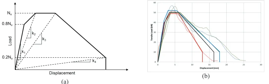
In the present study, a pentalinear format similar to that used by Sharma et al. (2014) has been used for idealization of the monotonic load deformation envelope under tension and shear for both the anchors. The effects of crack-width on the load deformation behavior are considered by introduction of factors for ultimate load and stiffness. Each of the monotonic load deformation envelopes obtained in the experimental program under tension as well as shear loading was idealized in the pentalinear format as shown in Figure 2 with a 123 step procedure. In the first step, the ultimate load plateau was assumed and horizontal lines corresponding to 80% and 20% of the ultimate were marked. In the second step, the loading part of the curve was idealized by two lines using the equal area approach. The degradation slope was decided on the basis of slope of the post peak curve between 100-80% of the ultimate load. This slope was extended till 20% of ultimate load. Typical pentalinear idealizations for the experimental curves are shown in Figure 2b. The pentalinear envelope thus obtained can be uniquely defined by five independent parameters—(i) ultimate load, (ii) stiffness K1, (iii) K2, (iv) K3 and (v) K4 as indicated in Figure 2a. Such a basic envelope is defined for each of the two anchors under tension and shear loading corresponding to the monotonic load deformation behavior in non-cracked concrete. In order to consider the effect of influence of crack widths on the load deformation envelope, multiplication factors for the above five parameters are defined.
INELASTIC BEHAVIOUR MODELS FOR HILTI® ANCHOR
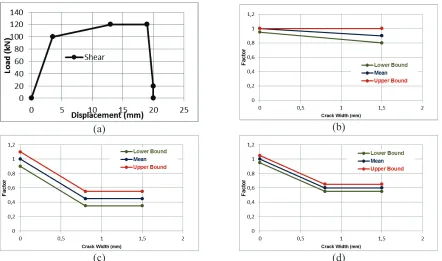
As described in part 1 of this paper and Table 1, tests were performed at constant crack width and varying crack width for the Hilti® HDA-T-22-M12x125/30 anchor. In each of these tests, monotonic load deformation envelopes following the different cycling protocols were evaluated. A comparison of these monotonic envelopes for different types of tests at given level of maximum opened crack width showed little variation of ultimate load capacities, stiffness values and failure modes. This is an indication of the ability of the anchor to retain its monotonic envelope in spite of different types of cyclic loading scenarios. However, the effect of crack width at which the load deformation envelope was evaluated, is observed to be significant. The mean pentalinear envelope obtained for the Hilti® anchor in non-cracked concrete, here forth referred to as basic envelope for the Hilti® anchor is shown in Figure 3a. As explained earlier, the envelope can be independently determined by definition of ultimate load, and four secant stiffness values. The variation of monotonic envelope for this anchor with increasing crack width
(ii) factor for initial stiffness K1 (Figure 3c) and (iii) factor for secant stiffness K2, K3 and K4 (Figure 3d).
(a) (b)
(c) (d)
Figure 3. Inelastic model for monotonic tension behaviour of Hilti® HDA-T-22-M12x125/30—(a) Basic
envelope (b) Load factor (c) Stiffness factor for K1 (d) Stiffness factor for K2, K3 and K4
(a) (b)
(c) (d)
Figure 4. Inelastic model for monotonic shear behaviour of Hilti® HDA-T-22-M12x125/30—(a) Basic
The values of the five independent parameters defining the monotonic envelope at any crack width level can be obtained by multiplying the parameter corresponding to the basic envelope with its respective factor corresponding to the crack width level. In view of the observed scatter during the experiments, a mean, lower and upper bound has been defined for the multiplication factors at different levels of crack width. The lower bound curves will provide conservative estimate for evaluation of displacements, while the upper bound curves will provide conservative estimates while evaluating forces. The basic envelope and crack width factors for behavior of Hilti® anchor under shear loading are shown in a similar fashion in Figure 4.
INELASTIC BEHAVIOUR MODELS FOR FISCHER® ANCHOR
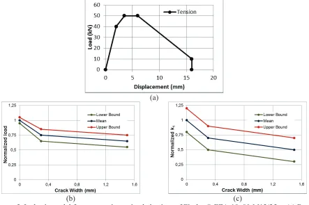
As described in part 1 of this paper and Table 1, tests were performed at constant crack width and varying crack width for the Fischer® FZA-18x80-M12/25 anchor. A comparison of these monotonic envelopes for different types of tests at given level of maximum opened crack width showed little variation of ultimate load capacities, stiffness values and failure modes. This is an indication of the ability of the anchor to retain its monotonic envelope in spite of different types of cyclic loading scenarios. However, the effect of crack width at which the load deformation envelope was evaluated, is observed to be significant. The basic envelope obtained for the Fischer® anchor is shown in Figure 5a. The variation of monotonic envelope for this anchor with increasing crack width could be considered with two
independent factors—(i) factor for ultimate load as indicated in Figure 5b, (ii) factor for secant stiffness
K1, K2, K3 and K4 (Figure 5c).
(a)
(b) (c)
Figure 5. Inelastic model for monotonic tension behaviour of Fischer® FZA-18x80-M12/25 —(a) Basic
envelope (b) Load Factor (c) Stiffness Factor for K1, K2, K3 and K4
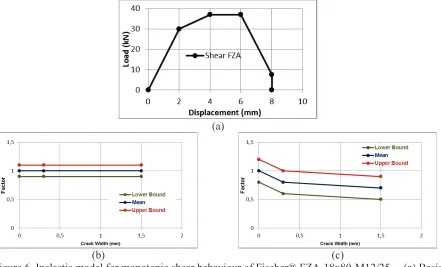
factor corresponding to the crack width level. In view of the observed scatter during the experiments, a mean, lower and upper bound has been defined for the multiplication factors at different levels of crack width. The lower bound curves will provide conservative estimate for evaluation of displacements, while the upper bound curves will provide conservative estimates while evaluating forces. The basic envelope and crack width factors for behavior of Fischer® anchor under shear loading are shown in a similar fashion in Figure 6.
(a)
(b) (c)
Figure 6. Inelastic model for monotonic shear behaviour of Fischer® FZA-18x80-M12/25 —(a) Basic
envelope (b) Load Factor (c) Stiffness Factor for K1, K2, K3 and K4
HYSTERESIS MODELS SIMULATING TENSION CYCLING
In order to simulate the tension cycling of the anchor loads observed in the tension cycling tests, a hysteresis model based on the pivot hysteresis rule (Dowell et al., 1998; Sharma et al., 2013) has been developed. The inelastic monotonic envelope developed in this study was used for the pivot hysteresis rule. The parametric constants required for definition of the hysteresis rule were obtained using the test data of the tension cycling phase. In order to consider the effect of crack cycling coupled with anchor tension load cycling, a special element with plastic deformation storing capability is required. The development of this special element and its hysteresis rule is in progress.
VALIDATIONS OF THE MODELS
(a) Experiment (b) Numerical Model
Figure 7. Comparison of monotonic tension load deformation curves obtained for Fischer® anchor
(a) (b)
Figure 8: Comparison of tension cycling obtained for Fischer® anchor in (a) experiment with (b) analysis
CONCLUSIONS
In this work, spring model simulating inelastic seismic behaviour of two undercut anchors qualified for their use in NPP application are developed. An experimental program covering all possible seismic loading scenarios in a conservative manner formed a basis for development of these models. The details of the experimental program and the results obtained therein are present in part 1 of this paper. This second part explains the analysis of the experimental results towards development of inelastic model. The model developed consists of a pentalinear spring that can be easily modelled in any commercially
available software. This spring is uniquely characterized by 5 parameters—one load value and four secant
stiffness values. The procedure for obtaining the spring characteristics at different levels of crack width using as minimum number of factors as possible is presented in this work for both the anchors. In view of the scatter observed during the experiments, mean, lower and upper bound curves are suggested for different crack width levels. The lower bound curves will provide conservative estimates for evaluation of displacements, while the upper bound curves will provide conservative estimates of forces. Depending on the requirements of the analysis and evaluation, suitable curves can be used.
ACKNOWLEDGEMENTS
The presented project was funded by the German Federal Ministry of Economic Affairs and Energy (BMWi, project no. 1501450 and project no. 1501478) on basis of a decision by the German Bundestag.
REFERENCES
ACI-355.2, 2007. Qualification of post-installed mechanical anchors in concrete (ACI 355.2-07) and
commentary. American Concrete Institute (ACI), Farmington Hills, Michigan.
Antaki, G., 2000. “Seismic retrofit of critical piping systems”. Workshop on the Mitigation of Eartquake Disasters by Advanced Technolgies (MEDAT).
ASCE-4-98, 2000. Seismic analysis of safety-related nuclear structures and commentary. American
Society of Civil Engineers.
DIBt-KKW-Leitfaden, 2010. Leitfaden für Dübelbefestigungen in Kernkraftwerken und anderen
kerntechnischen Anlagen (Guideline for fastenings in nuclear power plants and other nuclear technical facilities). Deutsches Institut für Bautechnik (DIBt), Berlin (in German).
Dowell, R.K., Seible, F., Wilson, E.L., 1998. “Pivot hysteresis model for reinforced concrete members”.
ACI Structural Journal 95.
Eligehausen, R., Mallée, R., Silva, J.F., 2013. Anchorage in concrete construction. John Wiley and Sons.
ETAG-001, 2006. Guideline for European technical approval of metal anchors for use in concrete, Parts
1 – 6. European Organization of Technical Approvals (EOTA), Brussels.
FEMA-E-74, 2012. Reducing the Risks of Nonstructural Earthquake Damage – A Practical Guide.
Fedaral Emergency Management Agency.
Krutzik, N., Tropp, R., 1993. “Verification of the local structural response of building structures in the anchorage areas of heavy components”. Nuclear engineering and design 141, 385–393.
Mahrenholtz, C., 2008. “Influence of high rate loading on Hilti HDA-Test Report Part1”. Report No: AF08/02-RWE07/01, Institut für Werkstoffe im Bauwesen, Universität Stuttgart , Germany. Mahrenholtz, P., 2012. “Experimental performance and recommendations for qualification of
post-installed anchors for seismic applications”. PhD thesis, Institut für Werkstoffe im Bauwesen, Universität Stuttgart, Germany.
Sharma, A., Eligehausen, R., Hofmann, J., 2014. “Numerical Modeling of Joints Retrofitted with Haunch
Retrofit Solution”. ACI Structural Journal 111, 861–872.
Sharma, A., Eligehausen, R., Reddy, G., 2013. “Pivot Hysteresis Model Parameters for Reinforced
Concrete Columns, Joints, and Structures.” ACI Structural Journal 110.
Yuceoglu, U., 1978. “Seismic design of equipment, supports and connections in industrial installations -Preliminary study”. Fritz Engineering Laboratory Report No. 424.3.