18th International Conference on Structural Mechanics in Reactor Technology (SMiRT 18) Beijing, China, August 7-12, 2005 SMiRT18-S03-5
NUMERICAL STUDY ON THE HEAT TRANSFER PHENOMENA IN
WATER POOL TYPE REACTOR CAVITY COOLING SYSTEM OF VERY
HIGH TEMPERATURE GAS-COOLED REACTOR
Dong Un Seo*, Moon Oh Kim, Hyoung Kyu Cho, Tae Wan Kim, Goon Cherl Park
Department of Nuclear Engineering, Seoul National University, Republic of Korea
Phone: +82 2 880 7216, Fax: +82 2 889 2688
E-mail: [email protected]
ABSTRACT
Many studies have been performed on High Temperature Gas-cooled Reactor (HTGR) which is able to make a mass production of hydrogen with economy and efficiency. The HTGR is designed to remove heat using passive cooling system in order to have an inherent safety and high heat removal capacity during the accident. Therefore, Reactor Cavity Cooling System (RCCS), is installed between the reactor vessel and the containment in cavity, is considered to remove heat during normal operation and accidents. The cooling type of RCCS was divided by cooling method water-cooled and air-cooled type. The concept of the water pool type RCCS, which was proposed at Seoul National University, consists of a reactor vessel, water pool surrounding the vessel, upper tank, cooling pipes and air supply system. It was designed to overcome the disadvantage of both the weak cooling ability of air cooled type and the complex structures of water cooled type. In this study, preliminary numerical analysis for experimental facility was performed to evaluate the proposed RCCS design. CFX was used for modeling of experimental facility and the surface temperature of cooler calculated by RETRAN-3D/INT was used as a boundary condition. The calculation results from CFX and RETRAN-3D/INT show good agreements with each other and it is found that the proposed RCCS design has sufficient cooling capability
Keywords: HTGR, RCCS, Water-cooled Type, Air-cooled Type, Water Pool Type
1. INTRODUCTION
Recently, the demands of hydrogen energy have increased as an alternative energy resource to solve the energy and green house effect problems. Many studies have been performed on HTGR which is able to make a mass production of hydrogen with economy and efficiency [1]. The HTGR has average coolant temperatures
above 900 and fuel temperatures above 1250 . The concept of HTGR allows a wide range of process heat
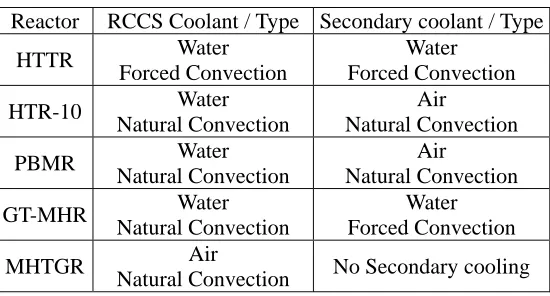
The cooling type of RCCS is classified by cooling method such as water-cooled and air-cooled type. RCCS of all HTGR are tabulated in Table1. The water-cooled type has the limitations of the water tank volume since the cavity is located between reactor vessel and containment [2-6]. In addition, it has a possibility of increasing the pressure of water tank as the boiling and evaporation. In order to provide high reliability of RCCS, it needs to be equipped with the complex systems such as heat exchanger. However, it has a sufficient cooling capacity. In the other hand, the air-cooled type has low cooling capacity. That provides the natural circulation of air through the chimney and has the possibility of releasing radioactive materials from cavity to atmosphere. Due to the natural circulation of air, however, it has more passively system than water cooled type and has the simplicity of cooling system without additional devices. In addition, it is possible to offer the long term cooling without forced cooling system. For these reason, the concept of RCCS, named water pool type RCCS, was proposed at Seoul National University to overcome the disadvantage of both the poor cooling ability of air cooled type and the complex structure of water cooled type.
As a part of those studies, preliminary calculation for evaluation of the concept of the RCCS was carried out. Numerical calculation for code-to-code benchmark was conducted using CFX5.7 code and RETRAN-3D/INT system code. Also numerical calculation for the heat transfer phenomena in water pool type RCCS was performed. RETRAN-3D/INT system code computed a surface temperature of cooling pipe and water temperature of water storage. [7] The CFX5.7 calculated to obtain detail information such as velocity and temperature distribution in water pool without simulating forced convection heat transfer of cooling pipes. After the data were fitted in 5th polynomial expression, it was used as a boundary condition of pipe surface on CFX5.7 code.
Table 1. RCCS in the HTGR
Reactor RCCS Coolant / Type Secondary coolant / Type
HTTR Water
Forced Convection
Water Forced Convection
HTR-10 Water
Natural Convection
Air
Natural Convection
PBMR Water
Natural Convection
Air
Natural Convection
GT-MHR Water
Natural Convection
Water Forced Convection
MHTGR Air
Natural Convection No Secondary cooling
2. CONCEPT OF THE WATER POOL TYPE RCCS
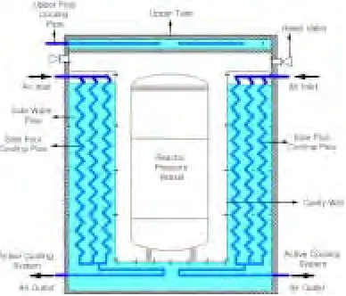
The water pool type RCCS was proposed to overcome the disadvantage of both the weak cooling ability of air cooled type RCCS and the complex structure of water cooled type RCCS. The schematic diagram of water pool type RCCS is shown in Fig. 1. This is different from water cooled type RCCS since water pools, between reactor vessel and containment, were used as heat sink during normal operation and the afterheat during the accident. The system of water pool type RCCS mainly consists of a reactor vessel, water pool surrounding the vessel, upper tank, cooling pipe which is installed in the water pool, and air supply system. In normal operations, the heat loss from the reactor vessel is transferred into the water pools via cavity. The heat is rejected to atmosphere by forced convection of air flowing through cooling pipe.
Due to this reason, we need to perform numerical studies to evaluate the feasibility of the water pool type RCCS as preliminary process of experiment. CFX code and RETRAN-3D/INT for numerical analysis used for the evaluation of the feasibility and optimization of the system. The experimental analysis for the validation of CFX code and RETRAN-3D/INT are planned to be performed.
In this paper, the numerical results were presented which were performed to investigate the heat transfer phenomena such as the natural convective heat transfer in the water pool and the forced convective heat transfer in the cooling pipe.
(a) Front View of Water Pool Type RCCS
(b) Top View of Water Pool Type RCCS
Figure 1. Concept of the Water Pool Type RCCS
3. TEST FACILITY FOR CODE EVALUATION
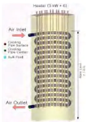
(a) Top View of Separate Test Facility
(b) Front View of Separate Test Facility
Figure 2. Geometry of Test Facility for Calculation
4. NUMERICAL CALCULATION
CFX code and RETRAN-3D/INT system code was used as preliminary calculation for the evaluation of water pool type RCCS to investigate natural or convective heat transfer. When heat transfer phenomena from the water pool to the cooling pipe is considered in CFX calculation, additional nodes for conduction calculation are required and the nodalization for the pipe thickness may cause the problem during mesh generation since the thickness of the pipe is quite small compared with the whole domain size. Therefore, in order to reduce the computation time and the number of mesh, air forced convection heat transfer of cooling pipe was not calculated and the temperature distribution along the cooling pipe surface is used as a boundary condition which is calculated by RETRAN-3D/INT [7] code. RETRAN-3D/INT is one-dimensional system code based on the RETRAN-3D [8] and developed by Seoul National University for the analysis of nuclear marine reactor.
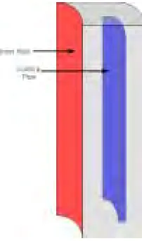
The CFX calculation was carried out to investigate the heat transfer phenomena in the water pool using surface temperature distribution of RETRAN-3D/INT. In order to reduce the computation time and the number of mesh, the calculation geometry of RCCS is simplified like duct shape. The calculation geometry of air pipe is shown in Fig. 5. It is designed to have a same heat transfer area with the pipe and the air does not flow in duct. It has only a function of heat sink to remove the heat from heater to water pool. The RETRAN-3D/INT data of the
cooling pipe surface temperature were implemented as boundary conditions. The k-ε model was used in the
turbulent modeling and the initial temperature of water pool was 45 oC. The cases of calculation are tabulated in Table2.
Table 2. The cases of Calculation
Heat Power (kW) Air Velocity (m/s) 32 m/s 48 m/s
CASE1 2.74 kW
58 m/s 32 m/s 48 m/s
CASE2 4.0 kW
58 m/s
Figure 3. Region of Calculation
Figure 5. Domain of CFX calculation
5. RESULTS
Fig. 7 to 12 show the calculation results of the temperature distribution of water pool and cooling pipe surface. The surface temperature of cooling pipe gradually increases as going to the outlet. Helical coil model was used in the calculation geometry of cooling pipe of RETRAN-3D/INT to simulate the heat transfer of cooling pipe with the U-bends shape. Due to the difference of heat transfer coefficient between the helical coil model and the actual pipe, the inlet surface temperature was lower than other surface temperature. In addition, RETRAN-3D/INT is not able to accurately calculate the pressure drop in bend of cooling pipe since it have a lumped nodalization of cooling pipe as shown in Figure5.
In the results of CASE1, the CFX code over-predicts the water pool temperature of bottom part by 3~4 oC
than results of RETRAN-3D/INT since CFX code does not calculate natural circulation between bends. The
natural convection of water pool happens between top part of cooling pipe and bottom part of cooling pipe due to the duct shape. Moreover, as the inlet velocity of air increases, the temperature difference between results of CFX code and those of RETRAN-3D/INT decreases. However, in the results of 4kW, RETRAN-3D/INT over-predicts the water pool temperature of top part by 3~4 oC than results of CFX code since the bulk temperature of water pool is influenced by fast inlet velocity. In other words, this means that heat transfer of top part of near inlet is not good.
The temperature difference between top of water pool and bottom of water pool is 2~3 oC. This means that the natural convection occurs in water pool. The velocity field in water pool is shown in the Fig. 13. Natural circulation was found as the upward flow in near the inner heating wall and downward flow in near the cooling pipe occur.
0.0 0.2 0.4 0.6 0.8 1.0 1.2 1.4 1.6 1.8 2.0
30 40 50 60 70 80 90 100
B
u
lk
Te
mperat
u
re[
°
C]
Height[m]
RETRAN-3D/INT CFX
0.2 0.4 0.6 0.8 1.0 1.2 1.4 1.6 1.8
30 40 50 60 70 80 90 100
Temperat
ur
e
[
°
C]
Height[m]
Surface Temperature of RETRAN-3D/INT
(a) Bulk Temperature of Water Pool (b) Surface Temperature of Cooling Pipe
0.0 0.2 0.4 0.6 0.8 1.0 1.2 1.4 1.6 1.8 2.0 30 40 50 60 70 80 90 100 B ul k Temperat ure[ ° C] Height[m] RETRAN CFX
0.2 0.4 0.6 0.8 1.0 1.2 1.4 1.6 1.8
30 40 50 60 70 80 90 100 Temperat ur e[ ° C] Height[m]
Surface Temperature of RETRAN-3D/INT
(a) Bulk Temperature of Water Pool (b) Surface Temperature of Cooling Pipe
Figure 7. Temperature distribution of Heat=2.74 kW and Velocity=48 m/s
0.0 0.2 0.4 0.6 0.8 1.0 1.2 1.4 1.6 1.8 2.0
30 40 50 60 70 80 90 100 B ulk Temperat ur e[ ° C] Height[m] RETRAN CFX
0.2 0.4 0.6 0.8 1.0 1.2 1.4 1.6 1.8
30 40 50 60 70 80 90 100 Temperat ur e[ ° C] Height[m]
Surface Temperature of RETRAN-3D/INT
(a) Bulk Temperature of Water Pool (b) Surface Temperature of Cooling Pipe
Figure 8. Temperature distribution of Heat=2.74 kW and Velocity=58 m/s
0.0 0.2 0.4 0.6 0.8 1.0 1.2 1.4 1.6 1.8 2.0
30 40 50 60 70 80 90 100 B ul k Temperat ure[ ° C] Height[m] RETRAN CFX
0.2 0.4 0.6 0.8 1.0 1.2 1.4 1.6 1.8
30 40 50 60 70 80 90 100 Temperat ur e[ ° C] Height[m]
Surface Temperature of RETRAN-3D/INT
a) Bulk Temperature of Water Pool (b) Surface Temperature of Cooling Pipe
0.0 0.2 0.4 0.6 0.8 1.0 1.2 1.4 1.6 1.8 2.0 30 40 50 60 70 80 90 100 B ulk Temperat ur e[ ° C] Height[m] RETRAN CFXe
0.2 0.4 0.6 0.8 1.0 1.2 1.4 1.6 1.8
30 40 50 60 70 80 90 100 Temperat ur e[ ° C] Height[m]
Surface Temperature of RETRAN-3D/INT
a) Bulk Temperature of Water Pool (b) Surface Temperature of Cooling Pipe
Figure 10. Temperature distribution of Heat=4.0 kW and Velocity=48 m/s
0.0 0.2 0.4 0.6 0.8 1.0 1.2 1.4 1.6 1.8 2.0
30 40 50 60 70 80 90 100 B ulk Temperat ur e[ ° C] Height[m] RETRAN CFX
0.2 0.4 0.6 0.8 1.0 1.2 1.4 1.6 1.8
30 40 50 60 70 80 90 100 Temperat ur e[ ° C] Height[m]
Surface Temperature of RETRAN-3D/INT
a) Bulk Temperature of Water Pool (b) Surface Temperature of Cooling Pipe
Figure 11. Temperature distribution of Heat=4.0 kW and Velocity=58 m/s
6. CONCLUSION
This study is focused on preliminary analysis by CFX code and RETRAN-3D/INT system code in the view of heat transfer phenomena on water pool type RCCS. The evaluation of CFX code and RETRAN-3D/INT was conducted for a quarter section of water pool to investigate the heat transfer phenomena such as natural circulation and convection. And the surface temperature of CFX code was input by the results of RETRAN-3D/INT, without considering the inside of cooling pipe.
The CFX5.7 calculation results were compared with those of RETRAN-3D/INT. Calculation of both CFX code and RETRAN-3D/INT for heat transfer phenomena of water pool results in good agreement. It was found that this facility for evaluation of water pool type RCCS had a sufficient cooling capacity and water pool temperature was maintained under boiling temperature. In the future, experimental analysis of test facility will be performed to validate the bulk temperature of water pool and heat transfer phenomena.
NOMENCLATURE
Q Heat [W] D Diameter [m] R Radius [m]
Subscript
in Inlet out Outlet cp Cooling pipe v Volume
REFERENCES
[1] M. Ogawa and T. Nishihara, “Present Status of Energy in Japan and HTTR Project,” Nuclear Engineering and Design, Vol.233, Issue 1-3, pp.5-10, 2004.
[2] IAEA, “Heat Transport and Afterheat Removal for Gas Cooled Reactors Under Accident Conditions,” IAEA-TECDOC-1163, Vienna, 2000.
[3] S. Saito et al., “Design and Safety Consideration in the High-Temperature Engineering Test Reactor (HTTR),” IAEA-TC-389, Dimitrovgrad, 1989
[4] Z. Wu et al., “The design features of the HTR-10,” Nuclear Engineering and Design, Vol. 218, pp.25-32, 2002.
[5] IAEA, “Current status and future development of modular high temperature gas cooled reactor technology,” IAEA-TECDOC-1198, 2001.
[6] D.A. Dilling et al., “Passive decay and residual heat removal in the MHTGR,” IAEA-TECDOC-757, Juelich, 1982.
[7] J. H. Kim, et al., “Study on the Natural Circulation Characteristics of the Integral Type Reactor for Vertical and Inclined Conditions”, Nucl. Eng. Des., 207, pp. 21-31, 2001.
[8] M. P. Paulsen, et al., “RETRAN-3D – A Program for Transient Thermal-Hydraulic Analysis of Complex Fluid Flow Systems”, EPRI NP-7450, 1996.
1972.