Design & Experimental Validation of Shaft & Hub
of Vertical Indexing Machine under Rotating
Structural Condition
Meghna S Nehete1, Dr. R. V. Bhortake2
P.G. Student, Department of Mechanical Engineering, P.V.P.I.T, Bavdhan, Pune University, Pune, india1
Professor, Department of Mechanical Engineering, P.VP.I.T, Bavdhan, Pune University, Pune, india2
ABSTRACT: Industrial machine development required multiple dedicated mechanisms to make applications in real working. So as a part of machine here required a vertical indexing axle to make it stand able with the top loading boundary conditions after examining stability takes matter in it. To make flexible indexing with 360 degree from transferring components directions in conveying application this vertical axle handles 1200 N load on it and rotate to make feasible action in the machine ,so vertical axle and its bolting hub is designed to come up with the working and loading conditions fulfilment. Axle design performed by analysing the conditions also material selection took matters here for indexing application shaft compression effect and hub stability is analysed by FEA, also physical prototype experimentation validated the results and all outcomes to compare and conclude the project work.
KEYWORDS: Design of hub and axle, Experimentation of hub and axle & validation of experimentation.
I. INTRODUCTION
Present practices: Existing operations in machine three Operations are loaded on individual stations and are sequentially machining, drilling and Pneumatic debarring.
All stations are equipped with different tool posts and manifolds for supporting operations.
Now, in new development we need it to convert one common station which will allow multiple operations and for that conceptual indexing mechanism came out.
In the current system, it is observed that due to the large shape and size of working cabinet machine size optimisation quite difficult, all the operations performed inside the machine cabinet are on powerized conveying system now we are collecting all operation at one place with indexing the work table to reach out on operating station so vertical shaft and hub assembly required to make it feasible.
BACKGROUND OF THE INNOVATION:
The invention is primarily concerned with indexing of work holding devices although it may be used to index a tool holding device such as a clamp or vise-like element. The work holding device is indexed to various positions during machine operations on the work. Various indexing devices have been proposed in the past.
Requirement for indexing:
Spool /Axle needed to hold vertical load while operations are in action.
Axle assembly should hold machining and other forces along with component self-load also.
Axle and working table coupling and locking arrangement ,
Scope of Work
The work includes
Redesign of Standing indexing table
Design of coupling , axle and hub
Design of structure
Stress analysis of axle , hub
Stress analysis of structure
Validation of the system using Ansys workbench
II. LITERATURE SURVEY
This invention relates to indexing work structures of the types particularly adapted, although not limited, to mounting on the work table of an engraving or the like machine tool; and the nature and objects of the invention will be readily understood by those skilled in the art in the light of the following explanation and detailed description of a preferred embodiment or mechanical expression of our invention, from among various other embodiments, expressions, forms, designs, constructions and combinations of which the invention is capable within the broad spirit and scope there of as denied by the appended claims. It is a primary object of our invention to provide an indexing work structure by which a work piece may be indexed with precision successively to predetermined positions of index relative to a tool adapted to operate upon the work piece.
This invention relates to an indexing structure and jig structure for presses and particularly to a jig structure which is adapted to receive and release fragile work units which when compressed in the jig cavity are difficult to remove in undamaged condition. It is an object of my invention to provide a novel jig having a cavity defined by a base member and walls which are retractable in relation to the base member and adapted to contain fragile work units to be compressed in the cavity and thereafter released ‘by means which merely retract the jig sides.
A further object is to provide for a press having a vertically reciprocal ram, multiple position indexing means carrying a series of jigs, the indexing means being power actuated to automatically and sequentially move the several jigs containing work units into registry with the ram, and including means for operating the run in time dereliction to the movement of the indexing means; improved jigs and coating ejecting or releasing means for compressed work units in the several jigs.
II. PROBLEM DEFINITION
To formulate the solution for holding indexing platform in Special Purpose Machine.
Objectives:
To design Axle assembly for indexing the unit of dedicated machining Platform.
To develop the mounting of platform on vertical shaft for indexing,
To validate the strength of indexing drive axle for performing in Special purpose machine.
III. DESIGN AND DEVELOPMENT
Shaft Design Guidelines:
Keep shafts short and minimize cantilever designs.
Hollow shafts have better stiffness/mass ratios, but are more expensive.
Configure shaft geometry to reduce stress concentrations.
Remember that gears can produce radial, tangential, and axial loads.
Be aware of maximum shaft deflection requirements of bearings.
Shaft natural frequency should be as high as practical.
Input:
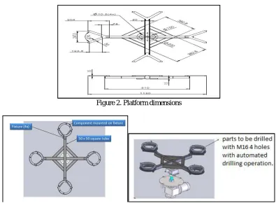
Bracket details and dimensions:Dimensions driven and are taken as per the area available for indexing and fixture mounting machine cabinet. Bracket is bigger role impact to make feasible assembly holding with cantilever support to hold each tool machine on all 4 positions.
Figure 2. Platform dimensions
Figure 3: Indexing Bracket CAD model Figure 4: Complete assembly ready to install in machine
III.1Design and development of Hub
Figure 5:Shaft Hub assembly Figure 6: Turning shaft hub layout
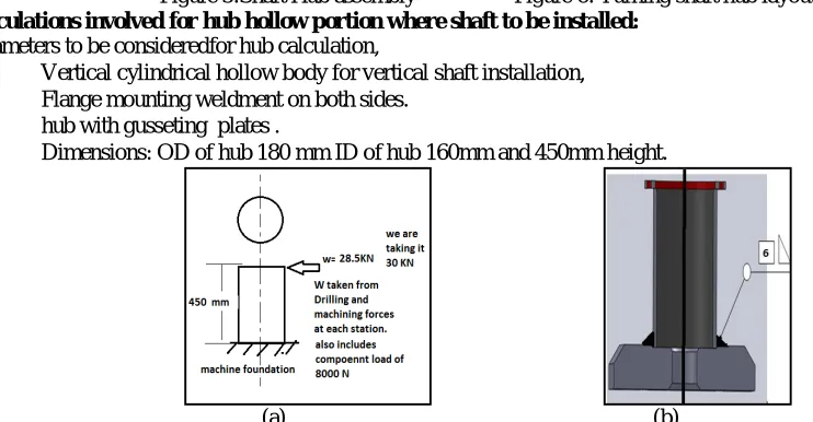
Calculations involved for hub hollow portion where shaft to be installed:
Parameters to be consideredfor hub calculation,
Vertical cylindrical hollow body for vertical shaft installation,
Flange mounting weldment on both sides.
hub with gusseting plates .
Dimensions: OD of hub 180 mm ID of hub 160mm and 450mm height.
(a) (b)
Figure 7: Hub design (a) showing details of hub and (b) is showing welding joint between drum hub and base mount.
Here to make deflection behaviour analysis while drilling forces comes on shaft which is holding by hub. Maximum deflection at top free end and given by,
= (1)
= .
Maximum Stress will be at support and given by,
= (2)
= . /
Figure 9: Gusset Geometry
STRING OPTIMISED GUSSTES SIZE 30X60X125
Since four gussets are capable to hold bending load, when arm loaded and activated against gusset and hub body load coming on single side and single side is acts on to bend on arm acting side so we are providing gusset to retrieve the normal condition against load. Now loads are expecting on four sides since arm is to be rotate and worked for 360 degree. And finally we used 4 gussets.
Total load on the single gusset is approximate 30 kN
Maximum deflection will be at free end and given by
= (3)
= 8.51
Maximum Stress will be at support and given by
= (4)
= 220 /
It’s too large and not practical Now,
It is found that the deflection and the stress developed in the gusset are exceeding the safe value. Hence the gussets are not safe and need to redesign.
Now
As Yield strength for steel is 215 MPa
the Maximum permissible stress for gusset be 215 MPa Hence
b = 29. 06 mm = 30mm Hence
Maximum deflection will be at free end and given by
= (5)
= 0.125
And
= 183.33 /
III.2 CAE VALIDATION
CAE validation of hub without gussets, hub with gussets and of only gussets are done. This validation gives results of maximum & minimum deformation and maximum & minimum stresses vale
CAE Part 1 – Hollow Shaft hub without gusseting
Hollow shaft holder hub bottom body is validated under Finite element method:Without applying gusting strength,
Figure 10: Force deformation Figure 11. Maximum stresses 77.45 MPa
In above both cases stress concentration is at hollow weld joint and it needs prefect gusseting to avoid weld weakness in the weldment assembly.
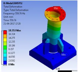
CAE part 2- Hollow Shaft hub with gusseting
Figure 12: Force graph (applied forces )
In figure 12 above graph it is shown how force change with respect to increasing time. This is calculated as now we are welding gussets to hub and force is going to act on welding point.
Figure 13 is showing the maximum equivalent stress value as 154.44 MPA and figure 14 is shoing maximum deformation value as 18.35mm.
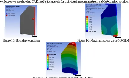
CAE Part 3 – Individual gusset part
In below figures we are showing CAE results for gussets for individual, maximum stress and deformation is calculated.
Figure 15: Boundary condition Figure 16: Maximum stress value 160.31MPa
Figure 17: Maximum deformation value 0.0678mm
Old material of slewing gear ring -42CrMo/50Mn as its bought out slewing ring
Bottom Casing material - cast iron.
New designed model material: S355 grade description: S355 structural steel is a high-strength low-alloy European standard structural steel covering four of the six "Parts" within the EN 10025 – 2004 standard. With minimum yield of 50,000 KSI, it meets requirements in chemistry and physical properties similar to ASTM A572. Typical applications include: US equivalent grade would be ASTM A572 GR50.
Why need of cylindrical shaft hub: Drilling on multistage machine tool for casting component with dedicated guiding elements and hollow cylindrical hub is best to routing spindle wiring, motors, and controllers also best to routine hydraulic hoses for coolant supply and lubrication. So assembly and mounting promoting here to use cylindrical hub and for base mounting of cylindrical structured assembly here is a need of HUB.
IV. EXPERIMENTAL SETUP
(a) (b)
Photograph 1: Practically performed experimentation photographs has been taken, (a) showing srtainguage which was used and (b) is showing blank machine setup on which experimentation is to be carried out.
This is the on which actual testing is to be carried out. The name of machine is Semi Automated Strain Gauge Output Analogger
Photograph No. 3: Actual Machine View
This is the photograph of Blank machine setup. The blue pipes are seen in this picture are pneumatic pipelines.
IV.1 PROCESSING TESTING ON COMPONENT
These strain gauges are fitted on blade by soldering operation. For strain gauge mounting surface should be cleaned and well prepared
(a) (b)
Photograph 3: (a) is showing hydro pneumatic load strain gauge reading and (b) is showing the stress effected areas on which we have calculated stress maximum value with the help of strain gauge.
By using pneumatic bar we have to apply force on blade assembly. Input Force = 5000+ N. Roughly access we got till 5500 N.
Photograph No. 6: Actual catched Strain Gauge Readings
IV.2 EXPERIMENTATION PROCESS CARRIED OUT
1. Fabrication of machine elements as per drawing
2. Surface Grinding of proposed stress observed areas for strain gauge mounting.
3. Strain gauge mounting as per guidelines. (4 gauges are mounted at different locations) put it on curing time as per the adhesive used.
4. Connecting strain gauges input wires with the loader machine. 5. Components loaded on fixturing platform on machine.
6. Adjust the component loading point portion towards cylinder stroke so the loading will be on appropriate portion.
7. Checked arrangement from experienced machine operator . 8. Verify the clamps and other holding devices.
9. Start the cycle push button.
10. Give load in Newton input to the software which interfacing user and machine.
11. Make couple of time repetition of stroking the hydro pneumatic loads on component. Take reading from strain value display unit.
IV.3 LAB REPORT
Photograph No. 7: Check List of Experimental Setup
V. RESULT
Outcome validation of CAE and experimental values is shown in below table.
Cylindrical shaft Hub
Parameters Design CAE Testing
Stress Mpa 62.5 77.45 71
Deflection mm 0.2 0.151
Gusset
Stress Mpa 183.33 160.31
Deflection mm 0.125 0.068
VI. CONCLUSION
Hub installed to hold indexing shaft is capable to sustain loads coming due to drilling on multistation platform. Hub and shaft assembly can be standardised for these kind of applications for Special Purpose Machines.
REFERENCES
[1] Ezra E. Tessener and Allen D. Gunderson, “Indexing Work Fixture”,Racine, Wis., assignors to George Machine Co., a coporation of Wisconsin Application, serial No.223.252, April 27, 1951.
[2] Raymond L. Schenk, Jr., Minneapolis, Minn., assignor to Gould-National Batteries, Inc., St. Paul, Minn., a corporation of Delaware, Filed May 2,1960, Serial no. 26034 & claims., Patented Nov 6, 1962.
[3] E. E. TESSNEER ET AL, “INDEXING WORK FIXTURE”, Filed April 27, 1951.
[4] Russ Edwin, “Indexing Fixture and method of indexing” ,Publication No: US3540312, Nov 17, 1970.
[5] R.L. SCHENK, JR, “INDEXING FIXTURE AND JIG STRUCTURE FOR PRESSES”, Serial no. 3,061,913, Filed May 2, 1960, Patended Nov. 6, 1962.
[6] Iain Boyle, “CAFixD – A CASE-BASED REASONING METHOD FORFIXTURE DESIGN, PhD dissertation Submitted to the Faculty of the WORCESTER POLYTECHNIC INSTITUTE in partial fulfilment of the requirements for the Degree of Doctor of Philosophy in Manufacturing Engineering ” May 2006.
[7] John L. Wickham, Glenarm, Md., “Rotary Indexing Mechanism, Md., The J. L. wickham Co., Inc., Baltimore Md., ontinuation of Set. No. 879,623, Jun. 27,1986, patented on Jan 2, 1990.
[8] Silvio T. Farfaglia, Fulton, “double ratchet conveyor drive mechanism, NY. Phillips Petroleum Company, Bartlesville, Okla. Filed: Sept. 7, 1973., Patented on Jan 14, 1975.
[9] David G. Connell, Milwaukee, “INDEXING COUPLING, Wis,Assignee The Falk Corporation,Milwaukee,Wis., Appl. No.: 715,682Filed: Aug. 19, 1976., Patented on Feb. 7, 1978.
[10]A textbook of Design of Machine Elements by B.D.Shiwalkar. [11] A textbook of Machine Design ByR.S.Khurmi and D.B.Gupta.