MODELLING OF A FLOW REDIRECTION DEVICE FOR THE
COOLING OF THE GAS BAFFLE
Juan Uribe1 and Mike Rabbitt2
1
EDF Energy R&D UK Centre. 2
EDF Energy Generation, Structural Analysis Group, Structural Integrity Branch.
ABSTRACT
In the Advanced Gas-cooled Reactors (AGRs) the hot box upper plenum is isolated from the graphite core by a baffle. Underneath the baffle there is a flow of relatively cool gas (T1) into a re-entrant plenum cooling both the baffle and the core. The baffle is insulated from the hotter gas in the upper plenum (T2) by permeable insulation packs. A bleed flow of T1 gas entering into the hot box through the baffle at its centre is used to cool the baffle in the reactor design. In this paper, a new device is presented that aims at redirecting the bleed flow to provide an enhanced cooling of the baffle. Several shapes and position have been analysed using Computational Fluid Dynamics (CFD) and their effect on the baffle cooling has been computed. The device is predicted to lead to a significant decrease in temperature over an area of 1.5m radius from the centre of the dome. Results are presented showing the thermal effects on the gas and the baffle of different shapes analysed.
INTRODUCTION
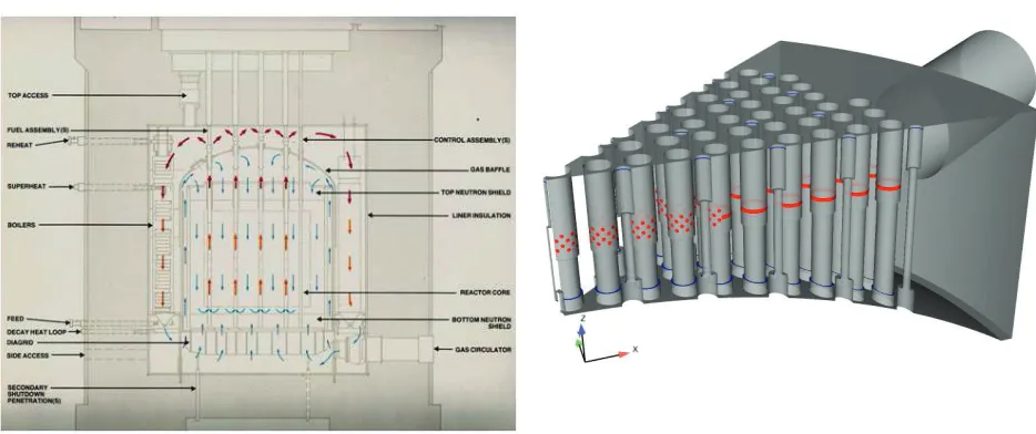
The Advanced Gas-cooled Reactors (AGR) in the UK are cooled by carbon dioxide. Figure 1 shows a schematic of an AGR and the gas flow inside it. High-pressure gas at a relatively low temperature enters fuel channels at the bottom of the graphite core, whereupon it is heated and flows upwards into fuelling guide tubes which penetrate the top of the core. The heated gas passes through the fuelling guide tubes and is discharged into the upper plenum of the reactor, following which it circulates through the boilers, then back to the core. The upper plenum is isolated from the graphite core by the baffle. Underneath the baffle there is a flow of relatively cool gas into a re-entrant plenum, cooling both the baffle and core. The temperature of the gas under the baffle is T1, whereas that in the upper plenum is T2. The baffle is insulated from the T2 gas by permeable insulation.
Figure . Schematic of AGR (left) and model used (right). Inlets colours: T2 gas in red, T1 gas in blue
The benefit of this blanket can change due to the mixing between the cold and hot jets that meet in this region. If there is too much mass flow relative to the hot jets, the cold gas will have more momentum than the hot flow and it will continue upwards and therefore the baffle will not see any cooling.
In order to take full advantage of the bleed flow of cold gas through the central CRGT, it has been proposed to fit a device that will redirect the flow towards the baffle rather than letting it be deflected by the hot gas from the pepper pot holes. This will create a layer of cold gas that will reduce the temperature of the gas being entrained within the permeable insulation and cool the baffle.
The purpose of this study is to analyse a series of shapes that could be introduced as flow-redirecting devices in an attempt to define how to obtain the maximum benefit.
GEOMETRY
The model consists of a 1/8th sector of the dome. It includes the fuelling guide tubes, control rods and the bleed flow outlets at the base of both (treated as inlet boundary condition in the present model). There is one outlet in the model. The model can be seen in figure 1
Figure
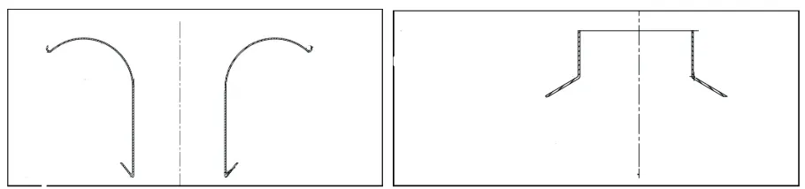
(right).In order to assess the effect of the possible redirection of the flow coming from the central Control Rod Guide Tube (CRGT) nozzle, two different types of shape have been studied. Type A shapes (see figure 2, left) are round shapes formed by an arc starting at the CRGT wall. They can be parameterised by the 3 points that make the arc. Type B shapes (see figure 2, right) are flat nozzles and are parameterised by two points, which determine the attachment point, the angle and the length.
Figure 2. Types of shapes studied, left: type A, right: type B
NUMERICAL SETUP
All results presented here have been obtained using the open-source software Code_Saturne (Fourier et. al., 2011). It is an unstructured, co-located finite volume code.
The mesh was created to use wall functions near the solid boundaries but the near-wall resolution along the central control rod has been increased to avoid the use of wall functions on that particular surface with a total cell count around 8 million. This was done to obtain a base flow solution without the assumption of wall functions since the resolution of the area where the hot and cold jets meet is important in determining the cooling effect on the baffle. This interaction is not well represented by conventional wall functions since they assume a universal logarithmic law. Once the surface of the shape is introduced, the direction of the flow will be determined by geometry thus the near-wall resolution is not as important. A further refinement has been made near the extracted volume boundaries in order to be able to resolve the details of the shape and to keep the growth ratio of the cells small. The meshes for the extracted volume for all shapes have about 1 million control volumes.
The turbulence model used is the SST model of Menter (1994). This model has been chosen in order to be able to automatically switch between wall function and viscous resolution in the regions where the non-dimensional wall distance is low. A second order linear upwind scheme has been used for all transported variables and a first order scheme has been applied to the time discretisation. An unsteady algorithm has been used and the main variables have been averaged over 50 flow-through times.
All physical properties have been modelled as a function of temperature. Gravity has been taken into account in the momentum equations and in the production of turbulent kinetic energy.
RESULTS
Base Flow
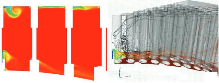
The flow without the addition of any device has been computed and is used to assess the advantages of the different shapes. In general, the flow is highly unsteady. The cold jet coming from the CRGT nozzle is deflected by the hot gas coming from the pepper pot holes.
There are other bleed flows with cold gas around the other control rod and fuelling guide tubes but their influence in the cooling of the dome is restricted to a small area around their base. Away from the centre, the cold gas at the bleed flow outlets is convected away by the main flow and with significant mixing.
Figure 3. Base flow, temperature contours (left) and streamlines (right).
Velocity field
The aim of the shapes studied here is to redirect the cold gas jet back towards the baffle in order to improve its cooling. All shapes produce the desired effect but with different levels of success.
In general, the A-type shapes produce small recirculation regions with complex patterns in the vicinity of the CRGT base. Type B shapes have less smooth behaviour and the result is a recirculation zone near the point where it meets the CRGT. The complex interaction with the base of the CRGT is important since it determines the momentum of the cold flow jet, which interacts with the hot gas. The momentum balance between the two streams controls how much they mix.
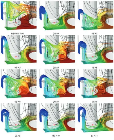
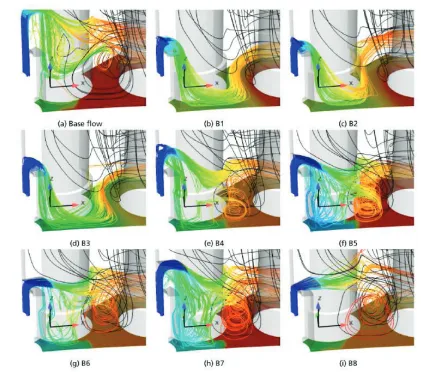
In order to visualise the effect of the different shapes on the flows the averaged velocity streamlines coming out of the central CRGT have been computed. They are presented in figures 4 and 5 coloured by the mean temperature. The streamlines from the pepper pot holes on the central fuelling guide tube are shown in black in order to appreciate where the mixing occurs.
All shapes reduce the temperature at the insulation cover plate in a larger zone around the central CRGT compared to the base flow. However, the mixing of the two jets is shape dependent. A-type shapes tend to produce a flow that remains attached to the insulation cover plate, except A4, A6, A7 which are the shapes that are characterised by a shorter arc and A8 which has a much larger radius of curvature (almost flat). For these four shapes, the predictions show a large vortex between the fuelling guide tubes. This promotes mixing between the two streams and therefore reduces the effectiveness of the cooling. The larger, circular shapes (A9, A10 and A11) produce a similar, cascading flow along the base of the CRGT whereas this ``cascade'' is not as smooth for shorter shapes (A2, A3 and A4). This is due to the interaction of the cold jet with the base of the CRGT. The shorter shapes produce an impingement on the horizontal part of the CRGT which disturbs the gas path.
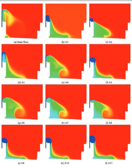
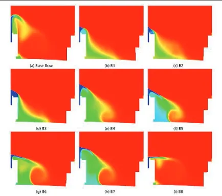
Temperature field
The temperature inside the upper plenum is dominated by the hot gas coming from the pepper pot holes. The effect of redirecting the cool bleed flow towards the baffle can only be seen in an area inside about a two-metre radius from the baffle centre. In figures 6 and 7, the contours of mean temperature can be seen for type A and type B shapes respectively. From these pictures is easy to see how some shapes produce a better cooling blanket effect than others. Shapes A1, A2 and A3 do a reasonable job but A9, A10 and A11 do better at keeping colder gas near the base of the CRGT. The shapes with smaller arcs (A4, A6, A7 and A8) cool more gas above the baffle, but this is not the desired effect. The B-type shapes produce a similar effect except B8 which produces little benefit compared to the base flow.
The baffle temperatures can be seen in the same figures. As mentioned earlier, the effect of adding a flow redirection device only affects the area near the centre before the second row of control rod guide tubes. Nevertheless, it provides a significant improvement in terms of direct cooling of the insulation cover plate compared to the base flow.
Shapes A1, A2 and A3 are the same but they differ in the height at which they are attached to the central CRGT. From the temperature profiles, it can be seen that the optimum location is somewhere in the middle. A9 and A11 have the same shape but with different attachment points. In this case, the best cooling is produced by having it as low as possible. This is because they are larger than the tube base and provide a free path for the flow to cascade downwards whereas the shorter shapes send the jet impinging on the horizontal surface of the tube base. The pairs B3-B4 and B6-B7 also have the same shape but different attachment points. They also tend to produce better results the lower they sit.
CONCLUSIONS
Several shapes of passive flow redirecting devices have been studied using CFD in order to improve the cooling of the baffle in an AGR.
Two different types of shapes have been studied, one arched (A-type) and one flat (B-type). The different designs have been added to an existing CFD model and their effect on the flow field and on the cooling of the baffle analysed.
The best overall cooling has been obtained by shape A9 which allows a clear separation between the cold jet coming from the bleed flow and the hot gas from the pepper pot holes. Although there are other shapes that can lower the temperature more, the area they affect is smaller.
There is a finite amount of cooling that can be generated and therefore all shapes produce a cooling effect restricted to a region inside a 1.5 metre radius from the centre of the baffle. The symmetry condition applied to the side boundaries blocks flow rotation about the baffle axis and forces the flow away from the centre. It follows that a periodic or full 360 degrees model would give a reduced cooling extent than predicted here. For a Reynolds Averaged Navier-Stokes (RANS) calculation (as presented here) the negative effect of applying the symmetry boundary condition would only be significant when there is a strong swirl. Since the swirl in the model can be only created from the asymmetric location of the tubes, rather than from the shapes introduced, it is not expected to be a strong effect.
REFERENCES
Y. Fournier, J. Bonelle, C. Moulinec, Z. Shang, A.G. Sunderland, and J.C. Uribe (2011). “Optimizing
F. R. Menter. (19994) “Two-equation eddy-viscosity turbulence models for engineering applications.” AIAA Journal, 32 (8) 1598--1605.