Electronic Theses and Dissertations Theses, Dissertations, and Major Papers
10-19-2015
Behaviour of Open Web Steel Joist in Composite Deck Floor
Behaviour of Open Web Steel Joist in Composite Deck Floor
System
System
Aiman M. Ibrahim Muhammad University of Windsor
Follow this and additional works at: https://scholar.uwindsor.ca/etd
Recommended Citation Recommended Citation
Muhammad, Aiman M. Ibrahim, "Behaviour of Open Web Steel Joist in Composite Deck Floor System" (2015). Electronic Theses and Dissertations. 5458.
https://scholar.uwindsor.ca/etd/5458
Composite Deck Floor System
By
Aiman Muhammad
A Thesis
Submitted to the Faculty of Graduate Studies
through The Department of Civil and Environmental Engineering
in Partial Fulfillment of the Requirements for
the Degree of Master of Applied Science at the
University of Windsor
Windsor, Ontario, Canada
2015
All Rights Reserved. No Part of this document may be reproduced, stored or otherwise
retained in a retrieval system or transmitted in any form, on any medium by any means
Deck Floor System
by
Aiman Muhammad
APPROVED BY:
______________________________________________ Dr. Nader Zamani, Outside Department Reader
Department of Mechanical, Automotive & Materials Engineering
______________________________________________ Dr. Shaohong Cheng, Department Reader
Department of Civil and Environmental Engineering
______________________________________________
Dr. Amr El Ragaby, Co-Advisor
Department of Civil and Environmental Engineering
______________________________________________
Dr. Faouzi Ghrib, Principal Advisor
Department of Civil and Environmental Engineering
I hereby certify that I am the sole author of this thesis and that no part of this
thesis has been published or submitted for publication. I certify that I have properly
acknowledged the contribution of other researchers to my thesis as provided in the
references. I certify the work presented therein is the product of my own work with the
guidance of my research advisors.
I certify that, to the best of my knowledge, my thesis does not infringe upon
anyone’s copyright nor violate any proprietary rights and that any ideas, techniques,
quotations, or any other material from the work of other people included in my thesis,
published or otherwise, are fully acknowledged in accordance with the standard
referencing practices. Furthermore, to the extent that I have included copyrighted material
that surpasses the bounds of fair dealing within the meaning of the Canada Copyright Act,
I certify that I have obtained a written permission from the copyright owner(s) to include
such material(s) in my thesis and have included copies of such copyright clearances to my
appendix.
I declare that this is a true copy of my thesis, including any final revisions, as
approved by my thesis committee and the Graduate Studies office, and that this thesis has
The objective is experimentally investigate the ability of other simple and fast to
apply shear connectors like puddle-welds and Hilti-screw to develop composite action
between the slab and girders. Two full-scale tests each consisted of 2400 mm wide, 6700
mm long and 65 mm thick concrete deck cast on top of corrugated steel sheets. The deck
slab is supported over two OWSJ each of 250 mm depth and spaced transversally at 1200
mm with 600 mm overhang on each side. The composite floor system is simply supported
in the longitudinal direction over 6400 mm span and was loaded monotonically till failure
under two line loads. Test results are presented in terms of load-strain and load-deflection
relationships at different locations over the concrete deck and across the depth. Test
results showed that significant composite action is developed at service load and can be
After thanking Allah, my almighty god, I would like to express my gratitude and
appreciation to my supervisors, Dr. Faouzi Ghrib and Dr. Amr El Ragaby for their
guidance and support which helped me to complete this work. Working with both Dr.
Ghrib and Dr. ElRagaby throughout the period of my Masters program at the University
of Windsor, helped me develop the skills needed to conduct my research.
My appreciation also goes to the respected thesis committee members Dr.
Shaohong Cheng and Dr. Nader Zamani for their advice and help. I would like also to
acknowledge the Canadian Joist and Deck Corp. for providing the materials and resources
needed for this project. Also, I would like to acknowledge the help of the lab technicians
at the Structural laboratory in testing and construction of the test specimens.
I would like to thank all my friends and colleagues for their company and
interesting discussions. My special appreciation is to my graduate colleague Gregory
Merryfield for his sincere help and support during the test specimens and whole my
research. I would like also to acknowledge the 2013 Capstone team Joseph Kairouz,
Edelyn Tria, and Alex MacIsaac for their help in the experimental testing.
I owe my deepest appreciation to my family for their continued support and
encouragement throughout all aspects of my life. Thank you for encouraging and
inspiring me in the pursuit of my goals. Especially, my mother’s prayers and love, which
acted as a shield that eased the hard times I experienced. I am also very grateful to my
Finally, my appreciation to all members of the department of Civil and
Environmental Engineering at the University of Windsor for their cooperative and giving
me this opportunity to be part of it.
University of Windsor Aiman Muhammad
DECLARATION OF ORIGINALITY --- IV
ABSTRACT --- V
ACKNOWLEDGMENTS --- VI
LIST OF TABLES --- X
LIST OF FIGURES --- XI
LIST OF ABBREVIATIONS --- XIII
CHAPTER 1: INTRODUCTION --- 1
1.1 GENERAL --- 1
1.2 COMPOSITE ACTION --- 3
1.3 PROBLEM STATEMENT --- 4
1.4 OBJECTIVES AND SCOPE --- 4
1.5 ORGANIZATION OF THESIS --- 5
CHAPTER 2: LITERATURE REVIEW --- 6
2.1 COMPOSITE CONSTRUCTION --- 6
2.2 OPEN-WEB STEEL JOIST (OWSJ) --- 8
2.2 EXPERIMENTAL STUDIES ON COMPOSITE CONSTRUCTION --- 10
CHAPTER 3: DETAILS OF THE EXPERIMENTAL PROGRAM --- 16
3.1 INTRODUCTION --- 16
3.3 TEST SET-UP, INSTRUMENTATIONS AND PROCEDURE --- 28
CHAPTER 4: ANALYSIS OF THE EXPERIMENTAL RESULTS --- 35
4.1 INTRODUCTION --- 35
4.2 ULTIMATE CAPACITY AND FAILURE MODE --- 35
4.3 LOAD-DEFLECTION BEHAVIOUR --- 37
4.4. LOAD -STRAIN BEHAVIOUR --- 44
4.5 STRAIN PROFILE --- 53
CHAPTER 5: CONCLUSION AND RECOMMENDATIONS --- 57
5.1 SUMMARY --- 57
5.2 RECOMMENDATIONS FOR FUTURE RESEARCH --- 59
REFERENCES --- 60
TABLE 1:CONCRETE AND STEEL STRAIN GAUGES IDENTIFICATIONS AND LOCATION ... 33
FIGURE (2.1):NON-COMPOSITE VS.COMPOSITE BEAM ... 7
FIGURE (2.2):NON-COMPOSITE VS.COMPOSITE-NEUTRAL AXIS ... 7
FIGURE (2.3)COMPOSITE TRUSS SYSTEM WITH HVAC DUCTS ... 9
FIGURE (3.1): SCHEMATIC DRAWING OF TEST SPECIMENS. ... 18
FIGURE (3.2):INITIAL LAYOUT OF CORRUGATED STEEL PANELS AND ... 20
FIGURE (3.3):HILTI-SCREWS ... 21
FIGURE (3.4):FORMWORK CONSTRUCTION ... 22
FIGURE (3.5):FORMWORK DETAILS ... 23
FIGURE (3.6):PLACEMENT UNDER THE ACTUATOR ... 23
FIGURE (3.7):FORKLIFT PLACEMENT ... 24
FIGURE (3.8):WELDED WIRE FABRIC ... 24
FIGURE (3.9):CASTING CONCRETE ... 25
FIGURE (3.10):CASTING CYLINDERS -SLUMP TEST ... 26
FIGURE (3.11):FINISHING OF THE CONCRETE SURFACE ... 26
FIGURE (3.12):CURING OF THE CONCRETE SLAB ... 27
FIGURE (3.13):TEST SPECIMEN AFTER CURING ... 27
FIGURE (3.14):TEST SETUP ... 28
FIGURE (3.15):FULL VIEW OF THE TEST SET-UP ... 30
FIGURE (3.16):INSTRUMENTATIONS ... 32
FIGURE (4.1)FAILURE MODE OF TEST SPECIMEN CD-W ... 37
FIGURE (4.2):COMPARISONS OF THE LOAD- DEFLECTION BEHAVIOUR ACROSS THE DEPTH OF TEST SPECIMENS DURING CYCLE 1 ... 39
FIGURE (4.3):COMPARISONS OF THE LOAD- DEFLECTION BEHAVIOUR ACROSS THE DEPTH OF TEST SPECIMENS DURING CYCLE 2 ... 40
FIGURE (4.4):COMPARISONS OF THE LOAD- DEFLECTION BEHAVIOUR ACROSS THE DEPTH OF TEST SPECIMENS DURING CYCLE 3 ... 41
FIGURE (4.7) THE RELATIONSHIP BETWEEN STRAIN AND LOAD –1STDIAGONAL ... 45
FIGURE (4.8) THE RELATIONSHIP BETWEEN STRAIN AND LOAD –BOTTOM CORD ... 46
FIGURE (4.9) THE RELATIONSHIP BETWEEN STRAIN AND LOAD –TOP CORD ... 47
FIGURE (4.10):COMPARISONS OF THE LOAD AND STRAIN RELATIONSHIPS OF TEST SPECIMENS –TOP CORD ... 48
FIGURE (4.11):COMPARISONS OF THE LOAD AND STRAIN RELATIONSHIPS OF TEST SPECIMENS –BOTTOM CORD ... 49
FIGURE (4.12):COMPARISONS OF THE TOP CONCRETE STRAIN ACROSS THE WIDTH OF TEST SPECIMEN CD-W ... 50
FIGURE (4.13):COMPARISONS OF THE TOP CONCRETE STRAIN ACROSS THE WIDTH OF TEST SPECIMEN CD-S ... 51
FIGURE (4.14) THE RELATIONSHIP BETWEEN STRAIN AND LOAD – CONCRETE GAUGE 3 ... 52
FIGURE (4.15)COMPARISONS OF THE TOP CONCRETE STRAIN AND LOAD – CONCRETE GAUGE - CYCLE 3 ... 53
FIGURE (4.16)STRAIN PROFILE ACROSS THE DEPTH FOR PUDDLE-WELDS – AT 30 KN ... 54
FIGURE (4.17)STRAIN PROFILE ACROSS THE DEPTH FOR HILTI-SCREWS – AT 30 KN ... 54
FIGURE (4.18)COMPARISON OF THE STRAIN PROFILE ACROSS THE DEPTH – AT 30 KN ... 55
FIGURE (4.19)STRAIN PROFILE ACROSS THE DEPTH FOR PUDDLE-WELDS– AT 40 KN ... 55
FIGURE (4.20)STRAIN PROFILE ACROSS THE DEPTH FOR HILTI-SCREWS – AT 40 KN ... 56
Abbreviation Definition
CISC Canadian Institute of Steel Construction
OWSJ Open Web Steel Joist
HSS Hollow Structure Section
NBCC National Building Code of Canada
CD-W Puddle-Welding
CD-S Hilti-Screws
N.A. Neutral Axis
CHAPTER 1: INTRODUCTION
1.1 General
Composite construction is when more than one material is used in one structural
element to resist loads. Famous example is Reinforced concrete, which has internal
composite action between the concrete and the reinforcing bars. Another example in
bridges, steel girders is used to support the concrete deck, which can be called external
composite action. Composite construction is important because it allows the better use of
each material strengthens where needed, i.e. concrete in compression zone and steel in
tension zone. Therefore, composite steel-concrete structures are used widely in modern
bridge and building construction. Composite construction simply aims to make both
materials perform better together, or to strengthen the weaknesses of each material. The
challenge is to ensure that forces are transmitted effectively and safely between the two
materials and there is full strain compatibility (composite action) at the interfaces.
Composite construction as we know it today was first used in both a building and a bridge
in the U.S.A. over a century ago. The first forms of composite structures incorporated the
use of steel and concrete for flexural members, and the issue of longitudinal slip between
these elements was identified by Moore (1987). Nowadays, the construction community
is looking for the best way to achieve composite action between steel and concrete in
terms of reducing the installation time, higher safety level for workers, and lowest cost.
Composite steel construction is considered also as one of the most economical
structural steel beams, Open-Web Steel Joist (OWSJ), girders, or trusses with shear
connectors supporting a concrete slab, forming an effective T-beam flexural member
resisting primarily gravity loads (Liew, 2003). Canadian Institute of steel Construction
(2011), defines Open Web Steel Joists (OWSJ) as steel trusses of relatively low mass
with parallel or slightly pitched chords and triangulated web systems proportioned to span
between walls, structural supporting members, or both, and to provide direct support for
floor or roof decks. Specifically, joists can be designed to provide lateral support to
compression elements of beams or columns, to participate in lateral-load-resisting
systems, or as continuous joists, cantilevered joists, or joists having special support
conditions. The advantages of OWSJ include enlarged effective depths with minimal
increases in material as oppose to W-shape beams of similar depths, making them very
efficient. The effective depth of an OWSJ is the distance between the centroid of the top
and bottom chords. Due to the slim cross section of the top cord of OWSJ, it is highly
desirable not only to ensure composite action, but also to ensure that the top cord is
subjected to tension, and the N.A. lies in the concrete flange. Furthermore, Open-Web
steel joists shall be designed for loads acting in the plane of the joist applied to the top
chord assume to be prevented from lateral buckling by the deck.
The main advantages of combining the use of steel and concrete materials for
building construction are:
Ø Composite systems are lighter in weight (about 20 to 40% lighter than concrete
construction). Because of their lightweight, site erection and installation are
easier, and thus labour costs can be minimized. Foundation costs can also be
Ø The construction time is reduced, since casting of additional floors may proceed
without having to wait for the previously cast floors to gain strength.
Ø The steel decking system provides positive moment reinforcement for the
composite floor, requires only small amounts of reinforcement to control cracking,
and provides fire resistance.
Ø The construction of composite floors does not require highly skilled labor. The
steel decking acts as permanent formwork. Composite beams and slabs can
accommodate raceways for electrification, communication, and air distribution
systems. The slab serves as a ceiling surface to provide easy attachment of a
suspended ceiling.
Ø The composite floor system produces a rigid horizontal diaphragm, providing
stability to the overall building system, while distributing wind and seismic shears
to the lateral load-resisting systems.
Ø Concrete provides corrosion and thermal protection to steel at elevated
temperatures. Composite slabs of a 2-h fire rating can be easily achieved for most
building requirements.
1.2
Composite Action
Composite action occurs when two or more components act as a single structural
element, such as a concrete bridge and a steel girder. This composite action results in an
increase in strength and stiffness of the bridge girders compared to non-composite action
beam. When steel joist and concrete deck floor is subjected to bending, the deck and joist
with shear connectors are used for this purpose, which creates strain compatibility
behavior between the joist and deck, provided composite action. Composite action is
achieved by connecting the steel girder to the concrete slab to permit transfer of
horizontal shear force at the steel-concrete interface (Kwon, 2008).
1.3
Problem statement
To date, CSA S16-09 mandates the use of shear studs in order to obtain adequate
composite action in composite flooring. Shear studs require extra material costs and also
require long time to install. They’re also a trip hazard for the workers as well as welders
have to be hooked to the ground, which is a big concern especially in large roofs.
Currently, for roof applications, designers used to count only on the OWSJ to resist the
load and ignore any composite action to avoid using shear studs. The practice of building
composite flooring without shear studs provides a competitive advantage. Without having
to weld shear studs, money can be saved from material costs, faster and easier
construction. However, it results in using deeper cross section and reduced the effective
useable height. The objective of this research project is to determine if in fact, alternative
simple connectors can be used to achieve composite action without the use of shear studs.
1.4
Objectives and Scope
To date, neither the puddle weld’s nor the screw pins strength is considered in the
design and no composite action should be utilized in the analysis mostly due to the lack of
researched allotted to this topic. This research investigates alternative methods to connect
cost and speed the construction. The objective of this experimental program is to
determine if in fact, composite action can be achieved without the use of shear stud
reinforcement.
1.5
Organization of Thesis
The general approach of this thesis is to explore the design of shear connectors
such as Puddle weld and Hilti-screw, with more focus on the behavior mechanism
between Open web steel joist and corrugated steel with concrete deck. The thesis is
organized as follows: Chapter 2 introduces a background of related research work. In
Chapter 3, the Proposed research program which includes the design concept, material
properties, and test setup. The evaluation methodology and attained results are presented
in Chapter 4 including the comparison with these shear connectors alternatives. Finally,
Chapter 5 concludes all the contributions made in this thesis, and outlines future research
CHAPTER 2: LITERATURE REVIEW
2.1 Composite Construction
Composite Construction is when more than one material is rigidly connected to
each other to perform as one body. The purpose of this type of construction practice is to
bring out the strengths of each material as well as to strengthen the weakness of each
individual material. Due to the modular-like nature of composite flooring with Open-Web
Steel Joists (OWSJ), several floors can be quickly constructed and easily repeated so it is
an ideal design for buildings with the same floor after floor applications. In a composite
floor system, the concrete deck is poured onto steel decking sheets which act as formwork
for the concrete and supported over the span between OWSJ. This construction method
saves a tremendous amount of time and materials needed under typical flooring
construction, leading to great savings to the bottom line.
In comparison to non- composite flooring, composite flooring is stiffer, causing
less deflection as shown in Figure (2.1). Increased span lengths are possible with
composite flooring. Composite flooring also has a larger moment capacity, allowing for
smaller section sizes. The metal decking in composite flooring acts as formwork for
concrete decreases construction times. When used properly, composite construction will
Figure (2.1): Non-composite vs. Composite beam
(source: http://www.thecivilbuilders.com/2013/02/applications-of-composite-beams.html)
Figure (2.2): Non-composite vs. Composite- Neutral Axis
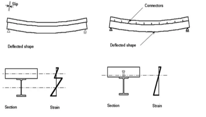
Composite action has a great effect on the stress and strain of a beam. Without
composite action, there is no strain compatibility at the interface between the two
materials, two neutral axis, causing the steel and concrete to operate under both
compression and tension, which leads to a smaller yielding/buckling load. With sufficient
composite action, there will be only one neutral axis (better if within the concrete slab),
allowing the concrete to take all the compression forces, while the steel beam takes
almost all the tension forces. Also, under the same load, a composite action beam will
have a much lower deflection than a non-composite beam as shown in Figure (2.2).
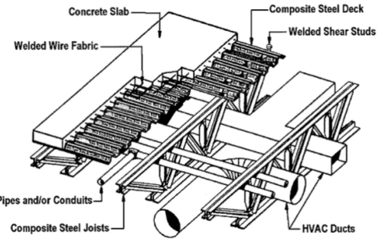
2.2 Open-Web Steel Joist (OWSJ)
Open Web Steel Joist (OWSJ) is an attractive structural engineering option for
increased strength and stiffness while offering sufficient opening for air ducts and other
services as shown in Figure (2.3). Composite joists are lighter and more
economical than non-composite joists. Composite joists with a deck-slab system will have
higher stiffness as well as better ductility than non-composite systems.
Based on Samuelson, D. (2002), the benefits by using composite steel joists include the
following:
Ø Ability to route the mechanical heating, ventilating, plumbing, and electrical lines
through the joist open webs. Customized web openings and configurations can be
provided for large ducts.
Ø Ease of relocating and/or moving future HVAC during the life of the building.
Ø Better plenum space utilization.
mechanical lines under the joists. Also the more efficient and stiffer composite
design makes it possible to support a given load with a shallower joist.
Ø Weight savings resulting from the efficient joist design reduces overall building
costs.
Ø Simplified erection and connections provide for fastest construction.
Ø Large column free areas give the building tenant maximum flexibility when
selecting a floor layout plan.
Ø Ability to provide customized composite joist designs for any given loading and
serviceability requirements.
Figure (2.3) Composite truss system with HVAC ducts
Composite Trusses or joists must provide sufficient factored resistance against
occupancy loading, deck placement, and concrete placement. The factored resistance
against collapse of OWSJ is dependent on the factored resistance of each of the following
individual components:
Ø Steel top chord member
Ø Concrete deck-slab as a top flange
Ø Steel bottom chord member
Ø Web framing members
Ø Shear studs
2.2 Experimental Studies on Composite Construction
A considerable amount of research has been performed on composite steel joists
over the past 50 years by experimentally testing the effective parameters of shear
connections. The previous studies were experimentally conducted in the U.S. utilizing
open-web steel joists in composite joists system in 1960’s (Samuelson, 2008) by
connecting open web steel joists with deck slab using shear studs only. The first testing of
composite joists was found in a 1965 Master of Science Thesis by H.G. Lembeck Jr.
(Lembeck, 1965); followed by Wang and Kaley (1967). In these earlier test specimens,
composite action was achieved by lowering the top chord angels so that the webs
extended above the top chord into the concrete slab. Corrugated steel forms resting on the
connection was created by the use of ½ in. (12.7 mm) diameter filler rods welded to the
top chord between the panel points. The tests were compared to conventional joists with
the same theoretical design load and the results showed that the composite steel joists
were stiffer, having about a 20 percent reduction in deflection at the design load. The
composite joists also attained an ultimate moment approximately 14 percent higher than
the conventional joists that were tested. In both research projects, the results indicated
that it was possible to achieve composite action in open-web steel joist construction.
Galambos and Tide (1970) performed tests on five composite steel joists that used
3/8 in. (9.5 mm) diameter x 2 in. (51 mm) long shear studs welded to the joist top chords.
A 3 in. (76 mm) concrete slab was cast over each of the joist specimens. The main
purpose of the research was to investigate the degree of composite action that could be
obtained by studying the stud shear connector behavior in a composite system comprised
of open-web steel joists, a cast-in place concrete slab, and mechanical shear connectors
holding the two together. The researchers varied the type and size of the joist top and
bottom chords as well as the number and location of stud shear connectors. The web
members were over-designed in all the test specimens to ensure there would be no web
failures in the experiments.
Cran, (1972) and Atkinson and Cran, (1972) tested composite steel joists
supporting 1 /2 -in. (38 mm) deep steel deck. Results from their study suggested that for
joists spaced more than 5 ft (1,524 mm) apart and with joist spans greater than 36 ft
Azmi (1972) conducted six tests on composite joists with 50 ft. (15.24 m) spans.
In addition to the testing, a design model was developed that showed good correlation
with the experimental data. The model was based on three levels of shear connection:
Under-connected, balanced, and over-connected which related the stud shear strength to
the tensile yield force in the bottom chord of the joist. Fahmy (1974) developed a finite
difference method to analyze the behavior of composite steel joists in both the elastic and
inelastic regime that considered two different methods for shear connection, puddle welds
and shear studs.
Robinson and Fahmy (1978) presented the experimental results and analysis of a
number of composite open-web joists with metal deck. The idea was to demonstrate that
composite with ribbed metal decking, would have sufficient ductility, and attain their
computed ultimate flexural capacities. The experimental programs tested four types of
OWSJ provided by three different manufacturing. They noticed that they have greater
stiffness, strength, and ductility than non-composite open-web joists. The load was
applied to the composite open-web joists at two points by means of a spreader beam. Test
spans of the joists were either 50 ft. (15.25 m) or 51 ft. (15.6 m). Each joist supported a 4
in. (101.6 mm) thick concrete slab incorporating a 19 in. (38.1 mm) deep ribbed metal
floor of 14-gauge material. Stud connectors and arc spot welds were placed between the
load points at approximately the same spacing as in the-shear spans. Test results showed
that composite open-web joists with ribbed metal floors have greater stiffness, strength
and ductility than non- composite open-web joists. All but one of the composite open-web
sufficient of them are used (a balanced or over-connected composite open-web joist) arc
spot welds provide an effective shear connection. In such a case vertical connection relies
on the bond between the ribbed metal deck and the concrete slab. It is likely that
composite embossed deck would be beneficial.
Leon and Curry (1987) and Curry (1988) reported on the testing of two full-scale,
36 ft. (10.97 m) long span composite steel joists to failure. Each test specimen was
constructed with 2 in. (51 mm) composite steel deck, 3/4 in. (19 mm) diameter headed
shear studs, and normal weight concrete with a nominal strength of 4 ksi (27.6 MPa).
Alsamsam (1988) tested another two full-scale specimens to failure. The major result of
the four tests was that the composite beam model could be used to predict the ultimate
moment capacity of composite steel joists.Patras and Azizinimini (19910 tested two
full-scale composite joists. The composite steel joists were 36 feet (10.97 m) long with a
nominal depth of 12 inches (305 mm). Top and bottom chords of both specimens
consisted of two equal leg angles welded back to back. Web members consisted of equal
leg angles placed on the outside of the chords. Galvanized deck supported the 4inch (102
mm) total concrete slab. Shear connectors, 3/4 inch (19 mm) diameter x 3.5 inches (89
mm) long after welding, were welded through the metal deck to the steel joist top chord
angles. Light weight concrete was utilized for both specimens. Test specimen CH-1 was
designed for a nominal strength of 3 ksi (20.7 MPa) while CH-2 was designed for a
nominal strength of 12 ksi (82.8 MPa). Crushing of the concrete adjacent to the shanks of
the “Weak” position shear studs in CH-1 was observed while there was no noticeable
load-carrying capacities were accurately predicted for both test specimens.
Kennedy and Brattland, (1992) studied the effect of concrete shrinkage on the
behavior of composite steel joists. The authors tested two full-scale 38 ft. (11.58 m)
specimens to failure, one at 65 days and the other at 85 days. It was found that the
majority of the shrinkage occurred in the first 30 days. The failure loads that the
specimens attained closely matched predictions based on an ultimate strength method
with only the bottom chord in tension. Easterling et al. (1993) discussed the composite
joist and slab systems. They tests four composite beams each of a single W16*31 section
with a composite slab and composite deck with a total of 6 in. thickness. The span of each
specimen was 30 ft. Welded wires were placed directly on the top of the deck and a total
of 12 headed shear studs, ¾ in.*5 in. Wang et al. (2011) conducted twelve push-out test
specimens of stud shear connectors with large diameter and high strength. The
researchers noticed that the use of studs with large diameter and high strength can
simplify the composite structure, save construction time and make the steel and the
concrete work together better. In addition, the shear resistance and shear rigidity were
higher than the normal studs used in composite structures and can be better used in bridge
structures. The specimens were designed according to the Eurocode 4, and 12 specimens
were conducted by considering different diameters and different strengths of studs, and
were divided into 4 groups. The length of each stud was 200 mm, and the diameters were
22mm, 25mm, and 30mm. The tested average compressive strength was 70.3 MPa after
28 days. Two specimens in each group were tested under monotonic load, and the other
structures and can be better used in bridge structures.
Hedaoo et al. (2012) presented the structural behavior of composite concrete
slabs. The slab is created by composite interaction between the concrete and steel deck
with embossments to improve their shear bond characteristics. However, it fails under
longitudinal shear bond. Eighteen specimens are split into six sets of three specimens
each in which all sets are tested for different shear span lengths under static and cyclic
loadings on simply supported slabs. Lakshmikandhan et al. (2013) investigated the
longitudinal shear transfer mechanism at the interface between steel and concrete. Three
types of mechanical connectors schemes were investigated experimentally which were
exhibited full shear interaction with negligible slip. These experimental were improved
strength and stiffness of the deck and can effectively reduce the cost of formworks. The
experts were noticed that the composite slab without shear connectors slips and fails at
the earlier load level. The insertion of shear connector modifies the brittle behavior of the
CHAPTER 3: DETAILS OF THE EXPERIMENTAL PROGRAM
3.1 Introduction
The proposed research is an experimental programs on full scale composite deck
prototype specimens. One test prototype used puddle welding between steel deck and
steel joist while the other test used Hilit-screw pin. The objective of this chapter is to
describe the proposed program, introducing the design concept, material properties, test
setup and instrumentation for the proposed specimens.
3.2 Experimental Investigation
The main objective for the proposed experimental program is to investigate the behavior
of open-web steel joist in composite deck floor system with different shear connectors.
3.2.1 Test specimens
The experimental program consists of assembling two composite decks without
any shear studs, one deck utilized puddle welding as a shear transfer mechanism and the
second deck utilized small screws for the same purpose. Each composite floor system
consists of three main elements; concrete slab, corrugated steel sheets and two OWSJ.
Two OWSJ, each is 250 mm in depth, were spaced 1200 mm apart in the transverse
direction and were simply supported over 6700 mm span in the longitudinal direction.
Corrugated steel sheets, each of 900 mm wide and 2400 mm long, were welded (test
specimen CD-W) or screwed (test specimen CD-S) to the top chords at single spot on
each of 600 mm wide. A welded wire fabric was placed at mid-height of the concrete slab
to mitigate cracking on the surface of the deck. The tested parameters in this experimental
investigation are the ability of puddle-weld and Hilti-screw pins to develop composite
action between the deck slab and supporting girders. Figure (3.1) shows schematic
drawing of test specimens.
(b) Side and elevation views of test specimens
Figure (3.1): schematic drawing of test specimens.
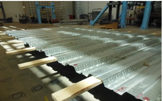
3.2.2 Details of constructions
Initially the two joists were rested parallel to one another at 1200 mm apart and on
two large steel reinforced I-Sections that were leveled and stabilized. The joists were then
secured to the I-Section using c-clamps. The decks were laid on top of the two trusses
with the flutes perpendicular to them, and were centered so that an overhang of 600 mm
on both ends was achieved. The decks where fastened temporarily at the ends using
c-clamps until they were welded or pin-screwed to the joist. Figure (3.1) shows the initial
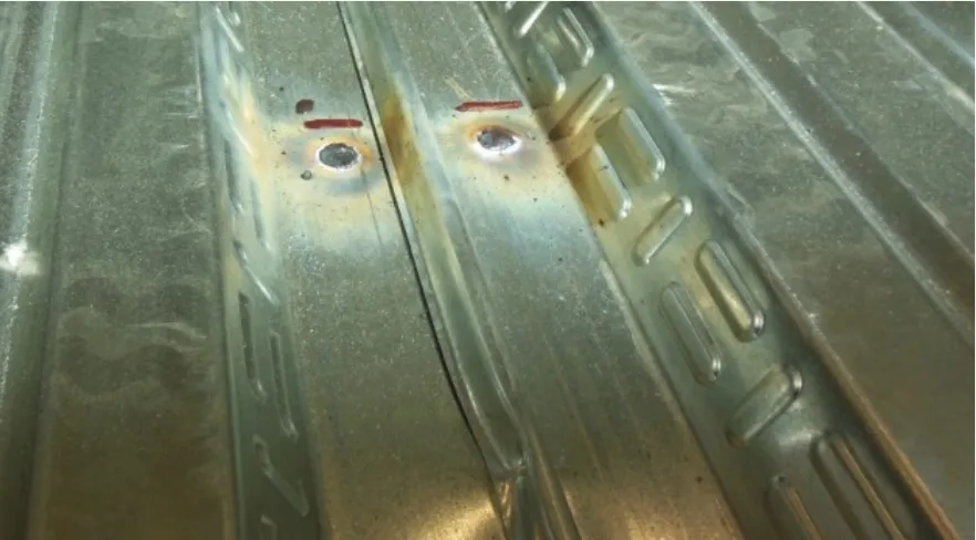
For the first test prototype, a professional welder was hired to apply 19 mm in
diameter Puddle-welds to only one angle of the top cord of each joist spaced at 300 mm
in the longitudinal direction using the arc weld machine to fasten the meal decking to the
trusses as shown in figure (3.2). Also deck sheets were secured to one another by
crimping the sections where the decks overlap. However, on the second test prototype,
Hilti-screws pins, 4 mm in diameter, were used instead of the puddle welds at the same
locations as shown in figure (3.3).
(b) Puddle weld
Figure (3.2): Initial Layout of Corrugated steel panels and
Puddle-Welds
Figure (3.3): Hilti-screws
After the decks were fastened to the joists, wood formwork was built underneath
the deck to support the fresh concrete placement. Two 8 by 4 foot sheets of plywood,
laminated on the one side, were used as the side edge of the forms to give the concrete a
smooth and even finish. Fourteen 2 by 4 by 10 feet lumber were served as the support for
the laminate plywood sides and lateral supports as well as to support the overhang weight
of fresh concrete. The 2 by 4’s were placed on top of, and perpendicular to, the joist under
every other flute of the deck as shown in figure (3.4).
The 48 by 96 inches laminate boards were cut, using a table saw, into eight equal
pieces of 6 by 96 inches. Two sheets of 48 by 96 inches plywood boards were each cut
into 4 equal pieces of 12 by 96 inches to be used as a ledge lying horizontally over top of
wedges to be secured on. The Laminate sheets were notched to fit on top of the 2 by 4
inch lumber so that the height of the form extends 65mm above the top of the flute.
Figure (3.4): Formwork construction
The laminate boards at the short side of the structure were rested on two 2 by 4
inch pieces that where secured by C-clamps to the I-section supporting the trusses. Three
2 by 4 by 10 feet lumber were each cut into ten equal pieces 1 foot in length, which in
turn were cut into two pieces from corner to corner forming two triangular wedges that
were used to secure the laminate plywood boards in place. The 6 by 96 inch laminate
plywood sheets were placed vertically over top of the plywood, three on each long side
and one on each short side. They were placed tight to the edge of the metal decking to
ensure that concrete will not flow out once poured. Figure (3.5) shows the details of
formwork. Figures (3.6) and (3.7) show the placement of the formwork and composite
deck under the loading frame. Once all parts of the form were cut to size, they were oiled
to prevent the concrete from sticking to them and to allow ease of removal once the
concrete slab and was located at mid-height of the 65 mm concrete slab 1 ½ inch ‘plastic
chairs’ as shown in figure (3.8).
Figure (3.5): Formwork details
Figure (3.6): Placement under the actuator
Figure (3.7): Forklift Placement
Figure (3.8): Welded wire fabric
A ready mix concrete with 28 days compressive strength of 30 MPa was used to
cast the deck slab. Figure (3.9) shows casting the concrete on the top of corrugated steel
and weld wire fabric were already placed.
Figure (3.9): Casting Concrete
A portion of concrete was set aside for some material testing (the slump test,
compressive strength). A slump test was performed and a slump of 70 mm was recorded.
Fifteen 4 by 8 inches and five 6 by 12 inches concrete cylinders were prepared for the
compressive and tensile splitting test. Figure (3.10) shows the details of casting cylinders
Figure (3.10): Casting cylinders - Slump test
Figure (3.11): Finishing of the Concrete Surface
The plastic and burlap sheeting in figure (3.12), was used for the moist curing of
the concrete for 7 days. The concrete cylinders were removed out of the moulds and
placed on top of the deck in order to have similar curing conditions. Figure (3.13) shows
Figure (3.12): Curing of the concrete slab
Figure (3.13): Test specimen after curing
3.2.3 Materials properties
All test specimens were constructed using normal weight, ready-mixed concrete
with a targeted 28-day concrete compressive strength of 30 MPa. All test slab prototypes
determined based on the average value of compressive and tensile splitting tests carried
out on standard cylinder specimens of 100x200 and 150x300 mm, respectively, on the
day of testing of the slabs. The standard cylinder specimens were cured under the
conditions as their reference slabs. The obtained average concrete compressive and tensile
strengths were about 32 MPa. The OWSJ used is CSA grade 350 steel, with 375 MPa
yield strength and 200 GPa elastic modulus.
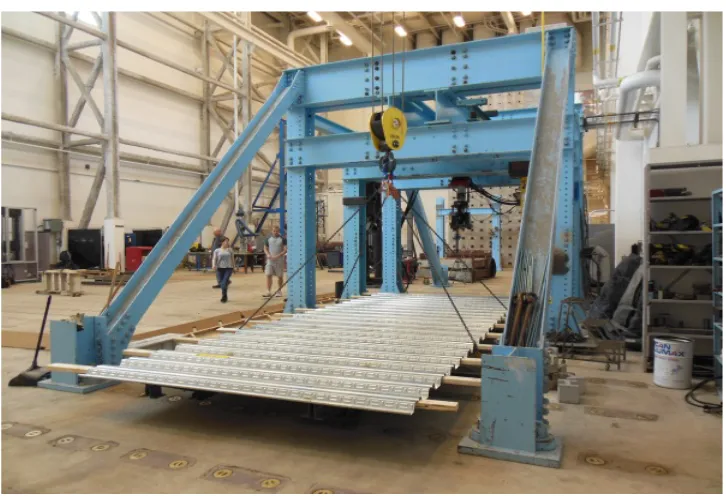
3.3 Test Set-up, Instrumentations and procedure
The composite floor system is simply supported in the longitudinal direction over 6700
mm span. It was loaded monotonically till failure under two line loads at the third points
as shown in Figure (3.14). Very stiff loading system was used to ensure uniform load is
applied over the entire width. The load was applied under load-controlled rate of 10
kN/min. three loading/unloading cycles were applied on each specimen. Figure (3.15)
shows the full view of the test setup.
The testing procedure followed the Performance Testing Procedure according to the CISC
(1980) as follows:
Ø Apply the load monotonically up to 25% of the ultimate load, then unloaded to
settle the joist.
Ø Apply the load monotonically up to 60% of the ultimate load and record the
deflection.
Ø Unloading the system and record the residual deflection.
Ø Apply the load monotonically up to 100% of the test load and record the
deflection.
Ø Unloading the system and record the residual deflection.
Ø Apply the load monotonically up to failure.
The ultimate load capacity was predicted to be 130 kN. Therefore, the peak load levels in
the three load cycles were set to 32, 80, and 130 kN respectively. Test load was
Figure (3.15): Full view of the test set-up
Several electric foil strain gauges, 10 mm long, were installed on the OWSJ
elements at critical locations, including top and front faces of the top cord as well as
bottom and front faces of the bottom cord, to monitor the strain distribution across the
depth of the composite deck during the test. Also, several electric foil strain gauges, 70
mm long, were installed on the top and front face of the concrete deck at different
locations to monitor the strain distribution across the width and depth of the concrete slab.
Three Linear Variable Displacement Transducers (LVDT’s) were mounted at mid-span
on the bottom cord, top cord and on top of the concrete slab over the OWSJ to record the
deflection values during the test. Hydraulic Loading actuator, 500 KN capacities with +/-
1250 mm stroke, was used to apply the load. It was mounted vertically in stiff steel frame
instrumentations. A data acquisition system, monitored by a computer is programmed to
record the readings of all strain gauges, LVDTs, and the load cell.
(a) Strain gauges on top concrete surface
(b) LVDTs locations
(c) Steel strain gauges location
The following table explains the strain gauges identifications and locations:
Table 1: Concrete and steel strain gauges identifications and location
Gauges Location
C1-TCC1 Placed on the top surface of concrete slab at the mid line
C2-TMC2 Placed on the top surface of concrete slab between C1 and C3.
C3-TEC3 Placed near the edge of the top surface of the concrete slab
C4-ESC1 Placed near the top edge on the side of the concrete slab
C5-ESC2 Placed near the bottom edge on the side of the concrete slab
S1-UDL
On the front truss, placed on the
underside of the diagonal on the far left side
S2-UBL
On the front truss, placed on the underside of the first bottom chord on the left side
S3-UTC
On the front truss, placed on the underside of the top chord under the centre line
S4-FTC On the front truss, placed on the face of the top chord under the centre line
S5-UBL
On the front truss, placed on the
S6-FBR
On the front truss, placed on the face of the bottom chord to the right of the centre line
S7-UBR
On the front truss, placed on the underside of the bottom chord to the right of the centre line
S8-UBL
On the back truss, placed on the
underside of the bottom chord to the left of the centre line
S9-UTC
On the back truss, placed on the underside of the top chord under the centre line.
CHAPTER 4: ANALYSIS OF THE EXPERIMENTAL RESULTS
4.1 Introduction
For a full-composite section, the failure need to be initiated by yielding of the
bottom cord of the OWSJ while the top cord is under tension forces or insignificant
compression force to avoid out of plane buckling. In another words, the neutral axis
should be located above the OWSJ top cord, i.e., within the concrete deck slab. From a
finite element analysis using STAAD Pro, it was concluded that, under these conditions,
the ultimate load capacity of the composite deck/OWSJ is about 130 kN. Therefore, the
peak load values of the three load cycles were chosen as 32 kN, 80 kN and 130 kN. The
preliminary test results are presented in terms of Load - deflections, Load- strains
relationships as well as ultimate capacity and failure load which were all measured during
the monotonic loading steps that were carried out on each test specimen. Also, sectional
strain distributions across the depth of the composite OWSJ are also provided to examine
the level of composite action.
4.2 Ultimate capacity and failure mode
Test specimen CD-W where welding was used to develop the composite action
showed a very promising performance. A full-composite action was observed during the
full range of load applied during the three load cycles up to failure. The specimen failed
at a total load of about 128 kN. The failure mode was mainly due local out-of plan
buckling of the top cord followed by shear-bond failure between the concrete slab and the
cord under the load as shown in Figure 4.1. However, specimen CW-S failed to show a
competitive behavior. The failure occurred at load level of 80 kN with excessive
deformation and delamination between the concrete and the deck slab. The failure was
initiated by slippage/bending between the hilit-screws and the deck followed by buckling
of the top cord.
(a) Test specimen Puddle-welds (CD-W) after failure
(c) Out-of plan buckling of top cord
Figure (4.1) Failure mode of test specimen CD-W
4.3 Load-Deflection Behaviour
Figures 4.2 to 4.5 show comparisons between the load vs mid-span deflection
relationships measured at the concrete top, top cord and bottom cord of each specimen
during the three load cycles. The consistency of the deflection behaviour and values
measured at the three levels in specimen CD-W reflects no slippage or delamination
between the components until high load levels, around 80 kN. This confirms the
significant composite action developed by the puddle welds. Specimen CD-S showed
incompatibility of deflection measured at the three levels due to the slippage occurred at
the interface between the deck and the top cord due to bending and sometime rupture of
between CD-W and CW-S during the three load cycles. It can be noticed Test specimen
CD-W showed a perfect linear load-deflection behaviour throughout all the loading
history up to 80 kN load without any residual (plastic) deformations after load cycles 1
and 2. The measured deflection at 40 kN "live load deflection" in figure (4.3) is about 6
and 12 mm for CD-W and CD-S respectively where the allowable is around 16 mm. On
the other hand, specimen CD-S showed a totally non-linear behaviour during all the
loading steps with significant residual deflections after all load cycles. This deflection
behaviour is in good agreement with the strain distribution showed before which confirm
the non-composite action behaviour of specimen CD-S.
(a) Specimen CD-W
0 10 20 30 40 50 60
0 2 4 6 8 10 12 14 16 18 20
Lo
ad
(kN
)
Mid-span deflection (mm)
(b) Specimen CD-S
Figure (4.2): Comparisons of the load- deflection behaviour across the depth of test specimens during cycle 1
(a) Specimen CD-W
0 10 20 30 40 50 60
0 2 4 6 8 10 12 14 16 18 20
Lo
ad
(kN
)
Mid-span deflection (mm)
top cord bottom cord concrete top
0 20 40 60 80 100
0 10 20 30 40 50 60
Lo
ad
(kN
)
Mid-span deflection (mm)
concrete top bottom cord top cord
(b) Specimen CD-S
Figure (4.3): Comparisons of the load- deflection behaviour across the depth of test specimens during cycle 2
(a) Specimen CD-W
0 20 40 60 80 100
0 10 20 30 40 50 60
Lo
ad
(kN
)
Mid-span deflection (mm)
top cord bottom cord concrete top Service load=40kN
0 20 40 60 80 100 120 140
0 20 40 60 80 100
Lo
ad
(kN
)
Mid-span deflection (mm)
(b) Specimen CD-S
Figure (4.4): Comparisons of the load- deflection behaviour across the depth of test specimens during cycle 3
(a) Specimen CD-W
0 20 40 60 80 100 120 140
0 20 40 60 80 100
Lo
ad
(kN
)
Mid-span deflection (mm)
Bottom cord Top cord concrete top
0 20 40 60 80 100 120 140
0 20 40 60 80 100
Lo
ad
(kN
)
Mid-span deflection (mm)
(b) Specimen CD-S
Figure (4.5): Comparisons of the load- deflection behaviour of test specimens measured at bottom cord
(a) 1st load cycle – Bottom Cord
0 20 40 60 80 100 120 140
0 20 40 60 80 100
Lo
ad
(kN
)
Mid-span deflection (mm)
1st cycle 2nd cycle 3rd cycle
0 5 10 15 20 25 30 35
0 2 4 6 8 10 12
load (kN)
Mid-‐span di0lection (mm)
(b) 2nd load cycle – Bottom Cord
(c) 3rd load cycle – Bottom Cord
Figure (4.6): Comparisons between the load and mid-span deflection relationships of test specimens
0 10 20 30 40 50 60 70 80 90
0 20 40 60 80 100
load (kN)
Mid-‐span di0lection (mm)
CD-‐W CD-‐S
Service load=40kN
0 20 40 60 80 100 120 140
0 20 40 60 80 100
load (kN)
Mid-‐span di0lection (mm)
4.4. Load - Strain Behaviour
Figure (4-7) to (4-11) shows comparisons of the load vs strain behavior of CD-W and
CD-S for the diagonal, top and bottom cords. It can be noticed that specimen CD-W also
showed a perfect linear behavior throughout all the load cycles up to about 80 kN load
level with almost no residual strains. The maximum recorded tensile strain was 1600
micorstrain which is less than the 1750 microstrain yielding strain. CD-W top showed a
tensile strain duo to 80 kN thereafter it changed gradually to a compressive strain of about
1150 microstrain at failure. This indicated that the neutral axis located in the top concrete
deck until a load level of about 80 kN. On the other hand, the top cord strains were
always a compression strains in CD-S and reached a high value of 1400 microstrain at
failure, only at 80 kN. Since load cycle #1, CD-S had the neutral axis below the top cord.
(a) Puddle-Welding
0 20 40 60 80 100 120 140
-‐200 -‐100 0 100 200 300 400 500 600
Lo
ad
(kN
)
Strain (micro strain)
(b) Hilti-Screw
Figure (4.7) the relationship between strain and Load – 1ST Diagonal
(a) Puddle-Welding
0 20 40 60 80 100 120 140
-‐400 -‐300 -‐200 -‐100 0 100 200 300 400 500 600
Lo
ad
(kN
)
Strain (micro strain)
1st cycle 2nd cycle 3rd cycle
0 20 40 60 80 100 120 140
0 200 400 600 800 1000 1200 1400 1600
Lo
ad
(kN
)
Strain (micro strain)
(b) Hilti-Screw
Figure (4.8) the relationship between strain and Load – Bottom cord
(a) Puddle-Welding
0 20 40 60 80 100 120 140
0 200 400 600 800 1000 1200
Lo
ad
(kN
)
Strain (micro strain)
1st cycle 2nd cycle 3rd cycle
0 20 40 60 80 100 120 140
-‐1200 -‐1000 -‐800 -‐600 -‐400 -‐200 0 200
Lo
ad
(kN
)
Strain (micro strain)
(b) Hilti-Screw
Figure (4.9) the relationship between strain and Load – Top Cord
(a) 2nd cycle
0 20 40 60 80 100 120 140
-‐1400 -‐1200 -‐1000 -‐800 -‐600 -‐400 -‐200 0
Lo
ad
(kN
)
Strain (micro strain)
1st cycle 2nd cycle 3rd cycle
0 20 40 60 80 100
-‐1000 -‐800 -‐600 -‐400 -‐200 0 200
Micro-‐strain
Load (kN) CD-‐S
(c) 3rd cycle
Figure (4.10): Comparisons of the load and strain relationships of test specimens – Top cord
(a) 2nd cycle
0 20 40 60 80 100 120 140
-‐1200 -‐1000 -‐800 -‐600 -‐400 -‐200 0 200
Micro-‐strain
Load (kN)
CD-‐S CD-‐W
0 20 40 60 80 100
0 200 400 600 800 1000 1200
Lo
ad (kN)
Micro-‐strain
(c) 3rd cycle
Figure (4.11): Comparisons of the load and strain relationships of test specimens – Bottom cord
Concrete strain gauges c1, c2 and c3 were used to ensure that the concrete
compressive strain is uniformly distributed across the top slab width, i.e. even load
distribution across the effective flange width. Figure (4-12) shows that uniform concrete
compressive strain/stress already developed in the concrete slab of CD-W while figure
(4-13) showed that due to failure of the hilti screws and yielding of the top cord of one joist,
the stress distribution in the top slab is not even. It can be noticed that the maximum
compressive strain of CD-W was about 175 microstrains at 128 kN while in CD-S was
about 220 microstrains at 80 kN.
0 20 40 60 80 100 120 140
0 200 400 600 800 1000 1200 1400 1600 1800
Lo
ad (kN)
Micro-‐strain
(a) Cycles 2
(b) Cycles 3
Figure (4.12): Comparisons of the top concrete strain across the width of test specimen CD-W
0 20 40 60 80 100 120 140
-‐200 -‐150 -‐100 -‐50 0
Micro-‐strain
Load (kN)
C3 C2 C1
0 20 40 60 80 100 120 140
-‐200 -‐150 -‐100 -‐50 0 50 100
Micro-‐strain Load (kN)
(a)Cycles 2
(b)Cycles 3
Figure (4.13): Comparisons of the top concrete strain across the width of test specimen CD-S
0 20 40 60 80 100
-‐500 -‐450 -‐400 -‐350 -‐300 -‐250 -‐200 -‐150 -‐100 -‐50 0 Micro-‐strain
Load (kN)
C3 C2 C1
0 20 40 60 80 100
-‐500 -‐450 -‐400 -‐350 -‐300 -‐250 -‐200 -‐150 -‐100 -‐50 0 Micro-‐strain
Load (kN)
(a) Puddle-Welding
(b) Hilti-Screw
Figure (4.14) the relationship between strain and Load – concrete gauge 3
0 20 40 60 80 100 120 140
-‐300 -‐250 -‐200 -‐150 -‐100 -‐50 0
Lo
ad
(kN
)
Strain (micro strain)
3rd cycle 2nd cycle 1st cycle
0 20 40 60 80 100 120 140
-‐300 -‐250 -‐200 -‐150 -‐100 -‐50 0
Lo
ad (kN)
Strain (micro strain)
Figure (4.15) Comparisons of the top concrete strain and Load – concrete gauge - cycle 3
4.5 Strain Profile
Figures (4-16) to (4-21) show the distribution of the measured strains across the
depth of the test specimens up to the equivalent service load, 40 kN in cycle 2. The
analysis of the strain measurements showed a linear strain distribution across the depth
where the neutral axis was located within the concrete deck up to a load level of 40 kN in
test specimen CD-W. Test specimen CD-S where screw pins were used to develop the
composite action showed very poor performance compared to specimen CD-W. It can be
noticed from the strain distribution that no composite action was developed. No strain
compatibility was observed at the bottom of the concrete slab and the top of the OWST.
Two neutral axes can be distinguish, one within the OWSJ and the second is within the
top deck. Local yielding in the top cord of the OWST was observed at different locations
0 20 40 60 80 100 120 140
-‐300 -‐250 -‐200 -‐150 -‐100 -‐50 0
Micro-‐strain
Load (kN)
Figure (4.16) Strain profile across the depth for Puddle-welds – at 30 kN
Figure (4.17) Strain profile across the depth for Hilti-screws – at 30 kN
-‐400 -‐350 -‐300 -‐250 -‐200 -‐150 -‐100 -‐50 0
-‐1000 -‐800 -‐600 -‐400 -‐200 0 200 400 600 800 1000 1200 1400 1600
Se
ct
io
n
he
ig
ht
fr
om
to
p
of
c
on
cr
et
e
de
ck
(
mm)
Strain (Micro-‐strain)
CD-‐W
-‐400 -‐350 -‐300 -‐250 -‐200 -‐150 -‐100 -‐50 0
-‐1000 -‐800 -‐600 -‐400 -‐200 0 200 400 600 800 1000 1200 1400 1600
Se
ct
io
n
he
ig
ht
fr
om
to
p
of
c
on
cr
et
e
de
ck
(
mm)
Strain (Micro-‐strain)
Figure (4.18) Comparison of the strain profile across the depth – at 30 kN
Figure (4.19) Strain profile across the depth for Puddle-welds– at 40 kN
-‐400 -‐350 -‐300 -‐250 -‐200 -‐150 -‐100 -‐50 0
-‐1000 -‐800 -‐600 -‐400 -‐200 0 200 400 600 800 1000 1200 1400 1600
Se
ct
io
n
he
ig
ht
fr
om
to
p
of
c
on
cr
et
e
de
ck
(
mm)
Strain (Micro-‐strain)
CD-‐S CD-‐W
-‐400 -‐350 -‐300 -‐250 -‐200 -‐150 -‐100 -‐50 0
-‐1000 -‐800 -‐600 -‐400 -‐200 0 200 400 600 800 1000 1200 1400 1600
Se
ct
io
n
he
ig
ht
fr
om
to
p
of
c
on
cr
et
e
de
ck
(
mm)
Strain (Micro-‐strain)
Figure (4.20) Strain profile across the depth for Hilti-screws – at 40 kN
Figure (4.21) Comparison of the strain profile across the depth – at 40 kN
-‐400 -‐350 -‐300 -‐250 -‐200 -‐150 -‐100 -‐50 0
-‐1000 -‐800 -‐600 -‐400 -‐200 0 200 400 600 800 1000 1200 1400 1600
Se
ct
io
n
he
ig
ht
fr
om
to
p
of
c
on
cr
et
e
de
ck
(
mm)
Strain (Micro-‐strain)
CD-‐S
-‐400 -‐350 -‐300 -‐250 -‐200 -‐150 -‐100 -‐50 0
-‐1000 -‐800 -‐600 -‐400 -‐200 0 200 400 600 800 1000 1200 1400 1600
Se
ct
io
n
he
ig
ht
fr
om
to
p
of
c
on
cr
et
e
de
ck
(
mm)
Strain (Micro-‐strain)
CHAPTER 5: CONCLUSION AND RECOMMENDATIONS
5.1 Summary
Composite floor system consists of concrete deck slab poured on top of corrugated
steel sheets supported over Open-Web steel Joist (OWSJ) is widely used in industrial and
commercial building repeated floors, workshops and warehouses. Composite flooring
offers larger moment capacity, allowing for smaller cross section sizes. Composite action
is the term used to describe the behaviour of composite structure which ensure strain
compatibility across the section which has a great effect on the stress and strain of beam
and floor composite systems. However, to achieve the desirable composite action,
extensive shear studs have to be welded on the top of the girder before concrete casting.
Such method imposes extra cost, time and construction difficulties. Some alternative
methods to connect the deck slab to the supporting girders (such as puddle welding or
Hilti-screw pins), are widely used during construction. To date, neither the puddle weld’s
nor the screw pins strength is considered in the design and no composite action should be
utilized in the analysis mostly due to the lack of researches allotted to this topic. This
research investigates the ability of puddle welding or Hilti-screw pins to develop
composite action, which will greatly reduce the cost and speed of the construction. The
objective of this research is to promote the application of composite floor system to
residential applications with the use of simple, yet effective connectors, without the use of