IM1200/IM2400
InterMail Voice Mail System
Administrator
Installation and Configuration Guide
DSG, DSG logo, AA9600, AA9604, VL880, InterMail, IM2400, IL1000 and IL5000 are trademarks of DSG
Technology. Windows and Outlook Express are trademarks of Microsoft Inc. Other names used here are
trademarks of their respective owners.
Copyright © DSG Technology, Inc. All rights reserved.
DSG Technology, Inc.
7F, 222 Cheng-Teh Road, Sec. 4, Taipei, Taiwan 111
Table of Contents 3
Table of Contents
Chapter 1 General Description ... 6New Generation Voice Mail ... 7
System Features ... 7
Auto-Attendant Features... 8
Voice Messaging Features ... 8
Chapter 2 Installing InterMail... 11
Package Content ... 12
Environmental Requirements ... 12
Telephone System...12
Network Environment...13
UMS E-Mail Server...13
Installing InterMail – IM1200 ... 13
Installing InterMail - IM2400... 15
Chapter 3 Installing IMS Utility... 19
Before You Start ... 20
Installing IMS Utility... 20
Login to InterMail... 20
Overview of IMS Utility... 22
IMS Basic Settings... 23
Using Setup Wizard ... 24
Chapter 4 Integration with PBX... 25
Selecting Your PBX ... 26
Call Transfer ... 26
Setting Up InterMail in Non-Supervised Mode ... 29
In-Band DTMF Strings ...30
Busy Time Lag...33
Setting Up InterMail in Supervised Mode ... 33
Call Progress Tone...34
Automatic Call Progress Learning ...35
DTMF Signall ...36
Setting Up InterMail in Semi-Supervised Mode ... 37
Busy Recall, Ring Releasee ...37
Call Pickup ...37
Chapter 5 Auto Attendant... 39
Creating Extension Blocks ... 40
Creating Operator & Extension Groups ... 41
Setting Channel Parameters ... 43
Designing an AA-Menu... 44
Recording AA-Menu Greetings...46
Transfer Options ...47
Defining Business Schedule ... 48
Defining Holiday Calendar ... 50
Chapter 6 Voice Messaging... 51
Defining Voice Messaging Parameters ... 52
Setting Up Message Notifications ... 53
Internal Notifications ...53
External Notifications ...55
Mailbox Management ... 55
Chapter 7 Unified Messaging System... 63
Setting Up E-mail Addresses ... 64
When Are E-mails Sent ... 65
Chapter 8 User Operations... 67
Accessing Your Personal Mailbox ... 68
Retrieving Your Messages ... 68
Sending a Message... 69
Editing Your Personal Mailbox Options... 70
Chapter 9 DTMF Programming... 73
DTMF Programming Mode... 74
Entering and Exiting the DTMF Programming Mode... 74
DTMF Programming Procedure... 74
DTMF and Action Code Table...75
3-Digit Function Code Table ...76
Chapter 10 Advanced Parameters... 99
Advanced Parameter 1... 100
Advanced Parameter 2... 101
Advanced Parameter 3 and 4 ... 102
Chapter 11 System Status and Backup ... 105
System Status... 106
System Alarm ... 106
System Backup & Restore... 107
Parameters Backup & Restore... 108
Table of Contents 5
Appendix A: 3-Digit Function Codes ... 111
Appendix B: System Prompts ... 121
Appendix C: System Specifications... 141
Chapter 1
General Description
Chapter 1 General Description 7
New Generation Voice Mail
InterMail is a new generation voice mail system that combines the Internet with voice processing technologies to provide a robust, dynamic, and user friendly voice messaging system that meets your office communication needs today. Designed with small-and-medium size business customers in mind, its features and functionality nonetheless rival those used by Fortune 500’s.
System Features
y Easy PBX Integration: Integrating with PBX has never been easier. Simply pick the PBX from the PBX list and then select the call transfer method. The call transfer methods include Supervised, Non-Supervised,
Semi-Supervised, and Call Pickup.
y Network Based Voicemail Management Software (IMS): Gives you an easy graphical user interface to maintain the system via local and wide area network. With the ubiquity of Internet, you can have full control of the system from wherever the network is available.
y System Report: Offers the system administrator easy overview of call statistics, mailbox usage, system status and performance.
y Incoherent Configuration Report: Keeps track of all system configurations that are incoherent to other settings. This is very useful when the
administrator is trouble shooting the system configuration.
y Live System Monitoring: All system activities can be monitored through the network using the IMS utility program. The DTMF inputs and outputs at each voice channel can be captured by a built-in line monitor (digit grabber).
y Voice-Guided System Configuration: InterMail allows you to do the system setup and configuration changes using a simple touch-tone phone instead of running a PC. It makes the process easy by providing
comprehensive voice prompts that guide you through every step of the way.
y System Configuration Backup: The system parameters and mailbox configurations can be backed up to the system administrator’s local hard drive. This enables you to keep records of various installations and expedite disaster recovery process.
y Dedicated Hardware and Software: InterMail integrated, all-in-one, non-PC based architecture makes it a stable, secure, and reliable product. y Multilingual System Announcement: Users and callers can select the
y Name Directory: Gives the caller a quick and easy way to locate the person they are trying to reach by entering their first or last name.
y Holiday Greetings: The administrator can set up a holiday calendar containing single or a range of dates each capable of holding its own holiday greeting.
Auto-Attendant Features
y Custom Automated Attendant Menu: Up to 300 different Auto Attendant Menus (AA Menus) can be designed and used to handle calls differently per different time of day, day of week, and line of the system.
y Operator & Extension Groups: Extensions can be grouped together to form a team of operators, a department, or for other purposes. Different operator teams can be selected for Business Hours, Break Hours, After Hours, and Closed Days.
y Call Distribution: Calls can be distributed among group members in linear, circular, or ACD fashion.
y Automatic Call Forward & Do-Not-Disturb: These are convenient call answering options that can be individually set for each extension.
y Conference Call: If supported by your PBX, InterMail can transfer calls to an external phone number when the called party is not at his/her
extension.
Voice Messaging Features
y Unified Messaging System: Your voice message can be delivered to your e-mail address as a Wave file attachment. The messages can be categorized as new or old message after its delivery.
y Virtual and Multi-Tenant Mailboxes: Aside from Real mailboxes,
InterMail provides Virtual and Multi-Tenant mailboxes for messaging-only or extension sharing applications.
y Personal Distribution Lists: Each mailbox can define up to 9 personal message distribution lists. Messages can be sent to multiple recipients with a simple selection of a list.
y Automatic Message Forward: Lets you forward all messages to a co-worker’s mailbox or a distribution list when you are away. Messages can be easily shared this way without any of them being overlooked. y Versatile Message Notification: You can receive notification of incoming
Chapter 1 General Description 9
in effect, retry interval, and retry count.
y Urgent and Private Message Tags: Messages can be marked with different tags to indicate the nature of the messages. The playback of the messages can also be prioritized based on the tag.
Chapter 2 Installing InterMail 11
Chapter 2
Installing InterMail
Package Content
Thank you for purchasing InterMail Voice Mail System. InterMail includes two models: IM1200 and IM2400. The content might vary depending on the location and the dealer you have purchased the unit from. Report any damage or missing items in the package to your dealer right away.
Items in your package include:
y InterMail Unit (IM1200 or IM2400)
y Power Supply (12V DC) (IM1200)
y Power Cord
y Installation Guide and IMS Utility (CD)
y RJ-45 Network Cable
y RJ14-to-RJ11 Line Splitters
Note: The network cable provided is a straight cable. Should you need to connect a PC directly to the system, please prepare a crossover cable, i.e. pin 1, 3 and pin 2, 6 are swapped.
Environmental Requirements
The InterMail should be located in a dust-free environment that is near the trunk lines from your existing telephone system. The InterMail must have access to your network wiring if you plan to access InterMail through your LAN (Local Area Network) or WAN (Wide Area Network), or if you plan to use the Internet telephony features of InterMail.
It is highly recommended that you use an Uninterruptible Power Supply (UPS) in conjunction with the InterMail to protect against power surges and failures.
Telephone System
InterMail is compatible with most major brands of Telephone Systems/PBX, including:
Manufacturer Model (Examples)
ALCATEL 4200/4400, OmniPCX Office
AVAYA Partner, Merlin/Definity
NEC ICS7400/EDK, NDK, M80, M100, MCI140
NORTEL Mercator, Norstar, Option 11
Chapter 2 Installing InterMail 13
Philips D120, SOPHO FVM 805/810/300, DS-1000
SIEMENS Hicom 300, Hipath 4000
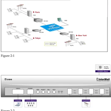
Figure 2-1
InterMail comes with 4 or 8 voice channels, and the same number of analogue ports is required from the Telephone System. In most cases, the VM ports from the Telephone System are the preferred ones to be connected to InterMail.
Network Environment
IP Networks
InterMail provides an Ethernet port allowing you to connect it to your IP network. Please prepare a fixed IP address for it. Then you will be able to access the system using IMS utility for further configuration.
Note: When using a PC accessing InterMail, please make sure your PC is located in the same subnet as the InterMail.
Direct Connection
When a LAN is not available, you could still access InterMail using a PC. Simply assign an IP address to the InterMail. Connect one end of a crossover cable to InterMail and the other end to your PC. Please make sure your PC is set to be in the same subnet as the InterMail.
Note: A crossover cable requires pin 1, 3 and pin 2, 6 swapped.
UMS E-Mail Server
InterMail can automatically send an e-mail with the voice message attachment to a designated e-mail address whenever a mailbox receives a new voice message. In order for this to work, a standard SMTP e-mail server with a valid e-mail address is required.
Installing InterMail – IM1200
Figure 2-1
Figure 2-2
Front Panel and LED Indicators:
y Mode Button: The Mode Button switches the Operation Mode of the IM1200. The Operation Mode will switch from Business Hours Æ Break Hours Æ After Hours Æ Closed Day Æ Business HoursÆ…, with each push of the button. The Operation Mode will automatically switch according to the Business Schedule, if it is set to Auto mode.
y Security Button: When the button is pressed down, all access to the system programming, including DTMF and IMS programming, will be blocked.
Note: This is the only button that has a locking mechanism. Be sure to toggle it back to normal position to allow system programming.
Chapter 2 Installing InterMail 15
y FUNC2 Button to reset system parameters: This button allows you to reset IP address, Administrator password as mentioned in FUNC1 and system parameters to factory default. To reset, turn off the power. Press and hold the FUNC2 Button and turn on the power. About 1 minute later system booting will complete. Till you see the Power and Mode LED on, then you can release the FUNC2 Button. The IP address, Administrator password and system parameters will be reset to the factory default.
y Power Indicator: The Power Indicator will be lit when the IM1200 has power connected and is turned on.
y Mode Indicator: The Mode Indicator will indicate which Operation Mode the system is in at the moment.
- Green: Business Hours - Amber: Break Hours - Red: After Hours - No light: Holidays
y Link Indicator: The Link Indicator will be lit when the system is connected to LAN.
y L1-L8 Line Indicators: The Line Indicator will be on when the indicated channel is being used.
Follow these steps to install IM1200:
1. Use the 2- or 4-wire phone cords to connect your phone system’s station ports to the jacks labeled L1/L2 to L7/L8 on the InterMail front panel. Plug the RJ14-to-RJ11 line splitters come with the package to split the ports to 4 or 8 channels and end to your phone system’s station ports.
2. Connect your Ethernet network with InterMail using a standard Ethernet (UTP CAT-5e) cable to the RJ45 jack labeled ETHERNET on the InterMail front panel.
3. Connect your power adaptor to the socket labeled PWR on the back panel of InterMail.
4. Connect the Battery cable to a 12-volt battery if you wish to use a battery for emergency power.
5. Turn on the power switch at the back of InterMail. Allow about 1 minute for it to finish the boot cycle.
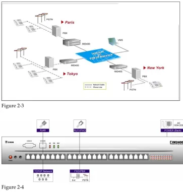
Installing InterMail - IM2400
Figure 2-3
Figure 2-4
Front Panel and LED Indicators:
y Power Indicator: The Power Indicator will be lit when the IM2400 has power connected and is turned on.
y Link Indicator: The Link Indicator will be lit when the system is connected to LAN.
y TX/RX Indicator: The TX/RX Indicator will be blinking when data is transmitting.
y Ready Indicator: The Ready Indicator will be blinking when system is on and the program is running.
y L1-L24 Line Indicators: The Line Indicator will be on when the indicated channel is being used.
Follow these steps to install IM2400:
Chapter 2 Installing InterMail 17
2. Connect your Ethernet network with IM2400 using a standard Ethernet (UTP CAT-5e) cable to the RJ45 jack labeled ETHERNET on the IM2400 front panel.
3. Connect your power adaptor to the socket labeled PWR on the back panel of IM2400.
Chapter 3 Using IMS Utility 19
Chapter 3
Installing IMS Utility
Before You Start
Before installing IMS utility, please make sure your computer conforms to the minimum system requirement blow:
y Windows 2000, XP
y Pentium III or higher
y Memory: 128 MB or higher recommended
y Available Hard Disk Space: 20 MB or above y CD-ROM drive (for installation)
y LAN for connecting to InterMail
Installing IMS Utility
You should find the latest IMS Utility from the Installation CD that came with your package.
1. Insert the DSG CD into the CD-ROM drive of your computer.
2. Select Installing IMS program. The setup wizard will start automatically. Or double click on setup.exe to install the program.
3. Follow the on-screen instructions to complete the installation.
Note: If the setup wizard does not start automatically, you could specify the location and install manually. From your Windows Start menu, select Run. In the Run dialog box, type 'd:\setup.exe', where 'd' is your CD-ROM drive, then click Ok.
4. After you complete the installation, you will see the IMS shortcut in the Programs Menu and on your desktop.
Login to InterMail
To launch the InterMail for the first time, make sure you have all the proper lines connected to the system. The default settings of InterMail are as below.
Item Default Settings
IP Address 192.168.1.200
Chapter 3 Using IMS Utility 21
Subnet Mask 255.255.255.0
DNS 168.95.1.1 Password 1234
Table 3-1
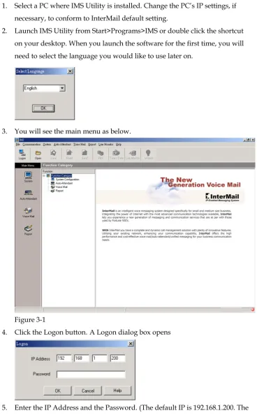
1. Select a PC where IMS Utility is installed. Change the PC’s IP settings, if necessary, to conform to InterMail default setting.
2. Launch IMS Utility from Start>Programs>IMS or double click the shortcut on your desktop. When you launch the software for the first time, you will need to select the language you would like to use later on.
3. You will see the main menu as below.
Figure 3-1
4. Click the Logon button. A Logon dialog box opens
default password is 1234.)
6. A new dialog box saying “Logon OK” will appear if you enter the correct IP address and password.
7. From the toolbar, click the Read button and click Start to import data from InterMail to IMS utility so that you could edit the settings later.
Note: You will stay connected for as long as there are actions on the IMS. If the IMS stays idle for 5 minutes, you will be automatically logged off from InterMail. Only one connection is allowed to access InterMail either from IMS Utility or DTMF Programming.
Note: You may start logging on to the InterMail if the factory default IP is applicable for the system in your network. You can also change the IP setting later using IMS when necessary. If the factory default IP is not available in your network, you can change the IP setting via DTMF Programming to one that is available in your network, so you can logon to InterMail using IMS. (For DTMF Programming, see Chapter 9)
Overview of IMS Utility
IMS provides user-friendly ways to program the InterMail, which include: y System Configuration: The settings of IP address, PBX Setup, PBX
integrated, Business Hours, Holidays and others.
y Auto-Attendant: Including AA menu, channel parameters, extensions and group settings.
y Voice Mail: Including mailbox parameters, notifications and personal options.
y Reports: Containing statistics of incoming lines and AA menu hit rates. y Open: To open saved data on the computer.
y Save: To save modified data to local computer, available for future references.
y Read: To importing data from InterMail to your computer via IMS utility. y Send: To upload modified data from your PC to InterMail.
y PBX: To specify a PBX model and import built-in parameters automatically. This will reduce the setting tasks.
y Date/Time: To define the system date and time.
Chapter 3 Using IMS Utility 23
and monitor the current status of each channel. y Wizard: Use Wizard to setup the system step by step.
IMS Basic Settings
After you log into the InterMail successfully, you will need to setup the basic items.
1. Go to Main Menu. Select System Configuration>System Parameters.
2. Password: InterMail provides two kinds of password. One for the system administrator; one for the person to record greetings. The administrator could edit all functions from DTMF Programming Mode or access the IMS utility. The person who uses Greeting Recording Password can only access Function 330 from DTMF Programming Mode to record greetings for protecting the system from non-technical engineers.
3. UMS: InterMail could send voice mails as wav file attachments via e-mail to extension users. Input the email address assigned to InterMail and the SMTP server IP address. If your mail server requires authentication, enable this option and input the associated account name and password.
4. IP Settings: Change the IP settings of InterMail allowing it to conform to your network configurations.
Using Setup Wizard
Chapter 4 Integration with PBX 25
Chapter 4
Integration with PBX
Selecting Your PBX
InterMail provides a PBX list for you to select to integrate your InterMail with your PBX the fastest and easiest way possible. The InterMail will be updated with the latest models of PBX periodically. Please contact your dealer for the latest PBX information. The default data and parameters are suitable for general conditions, and might be different from the specific and regional settings of your PBX. Check with the PBX dealer for the most accurate settings.
To Select a PBX
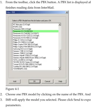
1. From the toolbar, click the PBX button. A PBX list is displayed after IMS finishes reading data from InterMail.
Figure 4-1
2. Choose one PBX model by clicking on the name of the PBX. And click OK. 3. IMS will apply the model you selected. Please click Send to export upload
parameters.
To Add a PBX Selection
1. Click PBX button. A PBX list is displayed.
2. Click Add button. A dialog box opens with folders for you to choose. 3. Choose the folder and the PBX file that you want to add, then click Open.
Call Transfer
Chapter 4 Integration with PBX 27
y Non-Supervised: The line is released when InterMail transfers a call under Non-Supervised Mode. The PBX should be configured to forward the call back to the VM port when the extension is not available. This mode allows InterMail to untie its resource and provides the best performance. This is the recommended call transfer mode. There are two ways Non-Supervised call transfer can be achieved:
- In-Band DTMF String: InterMail will check the In-Band DTMF String sent by the PBX for the reason (Busy or Ring/No-Answer) the call is sent back. This method requires the PBX be capable of sending In-Band DTMF Strings with condition codes when forwarding calls back to InterMail.
- Busy Time Lag:Some PBXes send the same In-Band DTMF strings for both Busy and No-Answer Call Forward. This method uses the time lag between receiving the Busy and No-Answer Call Forward when the call is bounced back from the PBX to determine the extension is Busy or No-Answer. This method is only recommended for certain PBX models.
y Supervised: In contrast to Non-Supervised Mode, Supervised Mode does not release the line when transferring the call. It instead holds and
monitors the line for the extension’s response. It then retrieves the call if the extension is not available, or releases the line if the call has been picked up by the extension. This mode will take up the most resource of
InterMail’s, but will be the only mode possible if the PBX does not provide any extension status information when calls are transferred. There are two things InterMail can use to monitor the call transfer:
- Call Progress Tone: InterMail monitors the Call Progress Tones (CPT) when transferring a call, and retrieves the call when the defined number of Busy or Ringback tones are received, then proceeds to take the call to the corresponding call flow.
- DTMF Signal: Instead of Call Progress Tone, InterMail looks for the DTMF Signal sent by the PBX when transferring the call. It will retrieve the call and process it according to the DTMF Signal it receives. Not all PBXes provide DTMF Signals for extension status. y Semi-Supervised: -In the case the PBX provides an incomplete set of
In-Band DTMF Strings, Semi-Supervised Mode can be used instead of Supervised Mode to free up some system resource.
- Busy Recall, Ring Release: InterMail will first operate under
Busy. If the extension is not Busy, the line will be released in the Non-Supervised Mode. This mode requires the Busy CPT parameters in the Supervised mode and the In-Band DTMF String for the
No-Answer condition in the Non-Supervised mode be set properly first.
- Call Pickup: Similar to Busy Recall, Ring Release method, the call is retrieved if it is Busy and released otherwise. InterMail will then use the Call Pickup function of the PBX to retrieve the call in a definite amount of time, assuming the call is not answered.
To configure the transferring codes:
No matter which transfer method you select, you will need to configure the transfer codes first.
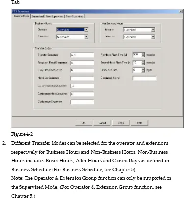
1. Choose System Configuration > PBX Parameters. Select the Transfer Mode Tab.
Figure 4-2
2. Different Transfer Modes can be selected for the operator and extensions respectively for Business Hours and Non-Business Hours. Non-Business Hours includes Break Hours, After Hours and Closed Days as defined in Business Schedule (For Business Schedule, see Chapter 5).
Note: The Operator & Extension Group function can only be supported in the Supervised Mode. (For Operator & Extension Group function, see Chapter 5.)
Chapter 4 Integration with PBX 29
DTMF and Action Codes
Code Action
0~9, *,#,A~D DTMF Signal
& First Hook Flash
h Second Hook Flash
, Pause for 0.5 second
; Pause for 1 second
X Extension Number
Table 4-1
y Transfer Sequence: Transfer Sequence transfers the call to the targeted extension. An example would be: [&,x].
y Ringback Recall Sequence: Ringback Recall Sequence retrieves a call when the extension status is No-Answer. An example would be: [&]. y Busy Recall Sequence: Busy Recall Sequence retrieves a call when the
extension status is Busy. An example would be: [&].
y Hang Up Sequence: Hang Up Sequence is used to disconnect the call. An example would be: [h].
y CO Line Access Sequence: CO Line Access Sequence hunts for an available CO line to make an external call.
y Conference Hold Sequence: Conference Hold Sequence puts the caller on hold while connecting the third party for a conference call.
y Conference Sequence: Conference Sequence connects the caller who was put on hold by Conference Hold Sequence to the third party that is reached through the External Conference Call Number defined in the mailbox.
y First Hook Flash [&]: InterMail provides two Hook Flash times for PBX programming. First Hook Flash is usually used for transferring calls. “&” is the symbol used to represent First Hook Flash time.
y Second Hook Flash [h] : Most PBXes only uses one Hook Flash time for all operations, while some PBXes require an alternative Hook Flash time to retrieve a call on hold. Second Hook Flash is usually longer than First Hook Flash. “h” is the symbol used to represent Second Hook Flash time. y Extension’s Size: Input the valid digit of extension numbers.
y Disconnect Signal: Input the PBX disconnect signal. 4. Click OK or Apply once you are done with the editing.
Setting Up InterMail in Non-Supervised Mode
strings when transferring calls. InterMail can make use of this information and determine what action should follow allowing ports to be released immediately.
Note: Please set the related parameters properly so that strings can be sent to InterMail. For example, the PBX has to enable the Busy/No-Answer Forward to the voice mail port.
In-Band DTMF Strings
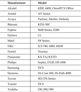
Examples of PBXes supporting Non-Supervised Call Transfer with In-Band DTMF Strings.
Manufacturer Model
Alcatel 4200, 4400, OmniPCX Office
Aristel AV Series
Avaya Partner, Merlin, Definity
Bitronic KDX-500
Fujitsu 9600 Series, E200
Hybrex Gi
Mitel SX Series
NEC ICS 740, M80, M100
Nortel Norstar Panasonic KX-TA/KXTD
Philips Sopho, D120, DS-1000
Samsung DCS
Siemens Hi-Com 300, Hi-Path 4000
Tecom SD/DX Series
Tonnet DCS Toshiba DK-280/380 Table 4-2
Chapter 4 Integration with PBX 31
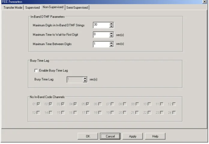
Figure 4-3
y Maximum Digits in In-Band DTMF Strings: The number of digits in the In-Band DTMF Strings will be different depending on the PBX models. This parameter will limit the maximum number of digits that can be received by InterMail. Digits exceeding this number will be ignored. y Maximum Time to Wait For First Digit: This parameter sets the
maximum time to wait for the first digit of the In-Band DTMF String sent by the PBX to arrive when a call is answered. If no digit is received at the end of this time, the call will be taken to the channel’s main AA menu greeting.
y Maximum Time Between Digits: This parameter defines the timeout between digits in the In-Band DTMF String sent by the PBX. If no further digit is received after this timeout, InterMail will stop the waiting and use the string received thus far to determine the status of the extension. y No In-Band Code: Specify channels not offering in-band code. Greetings
will be played immediately without detecting codes.
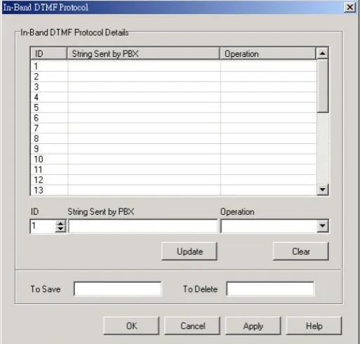
4. To Define the In-Band DTMF Protocol: Choose System Configuration > In-Band DTMF Protocol.
y String Sent by PBX: In-Band DTMF String sent by the PBX should be entered in this field for the InterMail to determine the status of the call transfer. The EXACT number of digits should be entered. InterMail will compare the actual string received from the PBX against the defined string here. The following codes should be used to compose the String Sent by PBX.
In-Band DTMF
Code Definition
0~9, *,#,A~D Represents one digit of DTMF.
E E Represents one digit of the extension
number.
I I Represents this digit should be ignored.
Table 4-3
y Operation: Select one of the following operations you want InterMail to execute when the actual DTMF string from the PBX matches the one defined in String Sent by PBX:
- To Main AA-Menu: InterMail will take the call to the prevailing AA-Menu and play that AA-Menu’s greeting defined for the channel. (For AA-Menu, see Chapter 5) This operation will be activated in the case when no strings in the String Sent by PBX fields can be found matching the actual string from the PBX.
Chapter 4 Integration with PBX 33
- To No-Answer Flow: The caller will be taken to the call path that handles the No-Answer situation for the extension, i.e., playing a personal not-available greeting and asking the caller to leave a message.
- To Access a Mailbox: The caller will be taken to the mailbox whose number is encoded in the string. This is usually used when the mailbox owner wishes to retrieve his/her messages and calls the voicemail from the extension directly.
- To Record on Demand: InterMail will record current calls. y To Save/To Delete: If the PBX supports recording function, input the
string representing save and delete recordings. 6. Click Update for every String defined or modified. 7. Click OK or Apply when done with all the modifications.
Busy Time Lag
Busy Time Lag is most useful when the PBX does not send No-Answer In-Band DTMF String or sends the same string for No-Answer and Busy situations. In such case, a countdown parameter is used to determine if the extension status is Busy or No-Answer. After the call is released, the countdown will start. If the call is bounced back during the countdown, the extension status will be
identified as Busy. If the call is bounced back after the countdown, the extension status will be identified as No-Answer.
1. Choose System Configuration > PBX Parameters. 2. Click Edit tab, a PBX Parameters dialog page appears. 3. Choose the Non-Supervised tab.
4. Define the following parameters:
y Enable Busy Time Lag: Checking this box tells InterMail to start the timeout counter for every transferred call.
y Busy Time Lag: This parameter sets the timeout value for the count down.
5. Click OK or Apply when done with all the modifications.
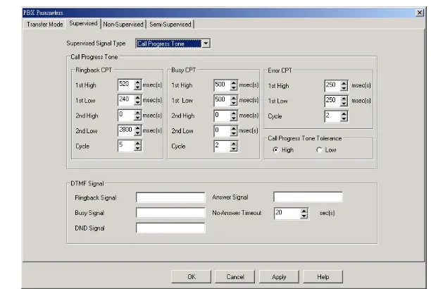
Setting Up InterMail in Supervised Mode
the line will be released. This transfer mode will take up the most resource of InterMail. There are two types of signals InterMail can monitor: Call Progress Tone (CPT), and DTMF Signal.
Call Progress Tone
Most PBXes send Call Progress Tones (CPT) while transferring calls to indicate the status of the transfer. If you are not sure about the tones, you may use Automatic Call Progress Learning function as described in the next section to get the parameters.
1. Choose System Configuration > PBX Parameters. 2. Click Edit tab, a PBX Parameters dialog page appears. 3. Choose the Supervised tab.
Figure 4-5
4. From the Supervised Signal Type list, select Call Progress Tone. 5. Define the following parameters:
y Ringback CPT: Ringback CPT may vary depending on the PBX model. Ringback CPT is usually composed of 1 ringing pulse, and 1 silence pulse.
Figure 4-6
Chapter 4 Integration with PBX 35
Figure 4-7
Define Ringback First High and Ringback First Low in milliseconds. If the PBX sends Ringback CPT with 2 ringing pulses, define the Ringback Second High and Ringback Second Low, or else set the two parameters to 0 milliseconds.
y Ringback CPT Cycle: This parameter defines how many times the Ringback Call Progress Tones from an extension should be received before the extension status is identified as No-Answer. InterMail will retrieve the call when the status has been confirmed.
y Busy/Error CPT: Similar to Ringback CPT, Busy and Error Call Progress Tones are composed of First High, First Low, Second High and Second Low parameters. Busy CPT is sent by the PBX to indicate the extension status is Busy, and Error CPT usually indicates the extension is not legal. Define these parameters, and leave Second Low and Second High as 0 if not needed.
y Busy/Error CPT Cycle: Similar to Ringback CPT Cycle, Busy and Error CPT Cycles define how many times the call progress tones should be received before the extension status is identified as busy or error. InterMail will retrieve the call when the status has been confirmed. y Call Progress Tone Tolerance: This parameter tells how much deviation
the actual call progress tones sent from the PBX can be from the set values. Select High or Low for the setting.
6. Click OK or Apply when done with all the modifications.
Automatic Call Progress Learning
Instead of manually entering the call progress tone parameters, InterMail provides an alternative way of capturing and learning and assigning those parameters to itself, called Automatic Call Progress Learning (ACPL) method. This method requires DTMF System Programming.
Learning Ringback Tones
learning target to monitor ring-back tone. 2. Make sure the extension is on-hook.
3. Enter Function Code [214] (Ringback CPT 1st High). Press [1#] when it prompts you to “Press 1 to edit, 2 to save, 3 to replay”. This will make InterMail call the extension.
4. After ringing the extension for a few times, it will reconnect to you and announce the value it has calculated and set for Ringback CPT 1st High based on the ringback pattern.
Note: It also has calculated and set other Ringback CPT parameters such as Ringback CPT 1st Low, Ringback CPT 2nd High/Low (when available), and Ringback CPT Cycle.
5. Press 2 to save the parameter.
Learning Busy Tones
1. Make sure the target extension is off-hook.
2. Enter Function Code [219] (Busy 1st High). Press [1#] when it prompts you to “Press 1 to edit, 2 to save, 3 to replay”. This will make InterMail to call the extension.
3. It will analyze the Busy Call Progress Tone coming from the ACPL extension and announce the value it has determined and set for the Busy 1st High parameter
4. Note: It also has determined and set other Busy CPT parameters such Busy CPT 1st Low, Busy CPT 2nd High/Low (when available), and Busy CPT Cycle.
5. Press 2 to save the parameter.
6. You have completed the Automatic Call Progress Learning process and assigned all the right values for the Ringback and Busy Call Progress Tone parameters to InterMail.
DTMF Signall
Some PBX sends DTMF Signals as well as Call Progress Tones to indicate call transfer status. Similar to the CPT, the DTMF Signal will convey the current extension status.
1. Choose System Configuration > PBX Parameters. 2. Click Edit tab, a PBX Parameters dialog page appears. 3. Choose the Supervised tab.
Chapter 4 Integration with PBX 37
5. Define the following parameters using the codes in the DTMF and Action Code Table (Table 4-1):
y Ringback Signal: Ringback Signal indicates the extension is ringing back. y Busy Signal: Busy Signal indicates the extension status is busy.
y DND Signal: DND Signal indicates the extension status is Do-Not-Disturb.
y Answer Signal: Some PBX provides the Answer Signal when the call is picked up by the extension. When this signal is received, the call will be released.
y No-Answer Timeout: Some PBX does not send Ringback Signal when transferring the call. In such case InterMail will hold the call for the No-Answer Timeout period and retrieve the call after the timeout. 6. Click OK or Apply when done with all the modifications.
Setting Up InterMail in Semi-Supervised Mode
This mode is the most commonly used when the PBX does not send a complete set of In-Band DTMF Strings. You will have 2 options in this mode. One is Busy Recall Ring Release; the other one is Call Pickup. For PBXes send DTMF signals for ringback and busy tone for busy, please apply Busy Recall Ring Release Mode. For PBXes supports call pickup, you may select Call Pickup option. Notice in Semi-Supervised mode, busy status will always be under Supervised Mode.
Busy Recall, Ring Releasee
When Callpick is not selected, you will be in Busy Recall, Ring Release Mode. Calls will initially be handled in the Supervised Mode when transferred, and InterMail will monitor for the Busy tone or the Busy DTMF signal. If the Busy CPT or the Busy DTMF Signal is not detected right away, the transfer is changed to Non-Supervised mode and the line released. When detecting ringback tones, lines will be release. You will need to setup the following items.
Ringback: Go to Non-Supervised Mode and define DTMF strings (as Figure 4-3). Then go to In-Band DTMF Protocol to input the String (as Figure 4-4).
Busy: Go to Supervised Mode. Set Busy Call Progress Tone parameters.
Call Pickup
In-Band DTMF String from the PBX to tell the call is not answered, InterMail will automatically use the Call Pickup function of the PBX to retrieve the call if the call is not answered by the extension after a pre-defined amount of time.
1. Choose System Configuration > PBX Parameters. 2. Click Edit tab, a PBX Parameters dialog page appears. 3. Choose the Semi-Supervised tab.
4. Define the following parameters:
Figure 4-8
y Enable Call Pickup: Check this box to enable the Call Pickup operation. y Call Pickup Sequence: The sequence to pick up the call that is ringing the
extension which is not answering to announce the No-Answer status to the caller.
y Call Pickup No-Answer Timeout: InterMail will attempt to pick up the call after this timeout, and announce to the caller the extension is not available.
y Call Pickup Channels: InterMail will use the selected channels to do Call Pickup operation.
Chapter 5 Auto Attendant 39
Chapter 5
Auto Attendant
Designing Your Auto-Attendant
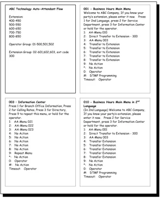
The Auto-Attendant in InterMail is very flexible and easy to configure. It is highly recommended that you prepare a draft for the Auto-Attendant flow that you want to use VMS to set up before hand. Below is a sample draft for the Auto-Attendant Setup.
ABC Technology Auto-Attendant Flow
Extension: 400-450 500-550 600-650 700-750 800-850
Operator Group: 01-500,501,502
Extension Group: 02-601,602,603, ext code 300
003 – Information Center
Press 1 for Branch Office Information, Press 2 for Calling Rates, Press 3 for Directory, Press 9 to repeat this menu, or hold for the operator.
1: AA-Menu 021 2: AA-Menu 022 3: AA-Menu 023 4: No Action 5: No Action 6: No Action 7: No Action 8: No Action 9: Repeat Menu *: No Action 0: Operator #: No Action Timeout: Operator
010 - Business Hours Main Menu in 2nd
Language
(In 2nd Language) Welcome to ABC Company, If you know your party’s extension, please enter it now. Press 2 for Service Department, press 3 for Information Center or hold for the operator.
1: AA-Menu 001
2: Direct Transfer to Extension - 300 3: AA-Menu 003
4: Transfer Extension 5: Transfer Extension 6: Transfer Extension 7: Transfer Extension 8: Transfer Extension 9: No Action *: No Action 0: Operator #: DTMF Programming Timeout: Operator
001 - Business Hours Main Menu Welcome to ABC Company, If you know your party’s extension, please enter it now. Press 1 for 2nd Language, press 2 for Service Department, press 3 for Information Center or hold for the operator.
1: AA-Menu 010
2: Direct Transfer to Extension - 300 3: AA-Menu 003
4: Transfer to Extension 5: Transfer to Extension 6: Transfer to Extension 7: Transfer to Extension 8: Transfer to Extension 9: No Action
*: No Action 0: Operator #: DTMF Programming Timeout: Operator
Figure 5-1
Creating Extension Blocks
Chapter 5 Auto Attendant 41
Figure 5-2 1. Choose Auto Attendant > Extensions.
dialog box opens.
pany you would like to edit.
number
e
orms to the Extension’s
e
Update after setting up one block, then continue to define the next
K or Apply once you are done with all the Extension Blocks setup
reating Operator & Extension Groups
ated extensions. With InterMail 2. Click the Edit tab. An Extension Blocks
3. Specify the following information for the block: y Company ID: Select the serial number of com
y Block ID: Select the serial number of Extension Blocks.
y Starting/Ending Extension: Set the starting and ending extension of the block. All extensions between the Starting and Ending Extension will be available for call transfer. The Starting Extension number must b smaller than the Ending Extension number and have the same number of digits as the Ending Extension number. If your extension numbers are not consistent, please set another Extension Block.
Note: Please make sure the extension digit conf
Size setting at System Configuration>PBX Parameter>Transfer Mode. y Assistant Extension: When an extension in is not answering or busy, th
call will be redirected to the Assistant Extension of that block. This is an optional attribute for each Extension Block, and is only supported in the Supervised Transfer Mode. (For Supervised Transfer Mode, see Chapter 4)
4. Click block. 5. Click O
you want.
C
An Operator & Extension Group is a group of rel
maximize the productivity of your Auto Attendant. You can also create mailbox and record a greeting for each group and access the group via Na Directory. It is very useful when you wish to use InterMail for call distribution management.
a me
Figure 5-3 1. Choose Auto Attendant > Operator & Extension Groups.
box opens. ed
rial number to edit.
Code represents this Group. Calls
ne existed
his group, such as Sales Dept.
ar: Calls will always be transferred to the first member of the 2. Click the Edit tab. An Operator & Extension Group dialog
3. Specify the Company ID. You will see the available extensions associat with the company.
4. Select a Group ID se
y Extension Code: Assign an Extension
for this group will be distributed to members of the group.
Note: Do not assign an Extension Code that is the same as o
regular extension. If so, the group will have higher call transfer priority than the regular extension number.
y Description: Fill in information for t
y Hunting Method: You can determine how to distribute calls for the group.
- Line
Chapter 5 Auto Attendant 43
transfer calls to the next member.
- Circular: The first call will be transferred to the first member and the
er of
l
extension number of
e modification of all groups.
perator Groups
el. Each channel represents a company.
nt business hours.
Setting Channel Parameters
ls. Each channel can be programmed
second call to the next member and so on. InterMail will keep track of which member should be the target for the next incoming call. - ACD: Calls will be transferred to the member taking least numb
calls. InterMail will track the number of calls successfully transferred to each member. The member with least number of calls answered wil be the target for the next incoming call transfer.
y Members: Refer to the available members, fill in the the group. You could set up to 10 members for a group. 5. Click Update for every group created or edited.
6. Click OK or Apply once you are done with all th
O
1. Specify a chann
2. Input the operator extension number in charge of differe
InterMail provides 4 – 24 channe
independently for individual greetings, languages, groups and others.
Figure 5-4
1. Choose Auto Attendant > Channel Parameters.
x opens.
calls after the set
: InterMail supports up to 4 different languages. If you 2. Click the Edit tab. A Channel Parameters dialog bo
3. Specify the following information for the channel: y Pickup After: The channel will pick up incoming
set your default language as English, for example, all of your call transfer announcements will be played in English. (The languages vary
depending on your location and installation. Refer to your dealer details.)
y Enable Ho
more
liday: When enabled, holiday greetings will be played during
pecify a company to use this channel.
eak Hours, After
one channel, you may click the Synchronize button to
e with all the modification of all
esigning an AA-Menu
300 AA Menus. The Auto Attendant is constructed holidays. Please go to System Configuration>Holiday Calendar to set up your holidays.
y Company ID: S
y Main AA Menu: Set AA Menu for Business Hours, Br
Hours and Closed Days. Different greetings will be played during different hours.
4. When finish editing
copy its settings to other channels. 5. Click Update to save setups.
6. Click OK or Apply once you are don channels.
D
InterMail provides up to
with independent scripts called AA-Menus. Each AA-Menu has its own greeting and customized action keys. From the menu, the caller can be guided to the extensions, service groups, operators, information bulletin, etc.
Figure 5-5 1. Choose Auto-Attendant > AA-Menu Man
ox opens. urs”. agement.
2. Click the Edit tab. An AA-Menu Management dialog b
Chapter 5 Auto Attendant 45
4. AA Menu Action: Assign each DTMF tone (0-9,*,# as shown on the key pad)
peat
u: The call will be transferred to another AA-Menu. Set the
h Language: The call will be transferred
ber: It is helpful when the first digit of the
to
st digit of an
ll be transferred to the target
ll
rst digit of the
age directly at
ll be asked to enter voice mailbox number
: Depending on your setting, callers will be prompted
red. with one specific AA-Menu Action. Possible actions are:
y 00 No Action: The system will play an error announcement then re the Menu.
y 01 AA-Men
target AA Menu ID accordingly. y 02-05 AA-Menu in 1st/2nd/3rd/4t
to another AA-Menu in the specified language. Input the target AA Menu ID in “Target” box. The following system prompts will also be switched to the specified language.
y 06 Lead to Extension Num
desired extension has been used or the extension number has a wide range. Callers need to press one pre-defined DTMF keys for being led the desired Extension Number. For example, if the caller wishes to reach extension "100" and “Lead to Extension Number” is set on "3", the caller should press "3” and then “100" for reaching extension 100.
y 07 Transfer to Extension: The assigned DTMF digit is the fir
extension to be transferred. For example, if the action is set on "1", callers will reach extension 100 by pressing “100”.
y 08 Direct Transfer to Extension: The call wi
extension directly. Set the target extension number accordingly. For example, if the action is set on "6" with the target set as "100", callers wi be transferred to extension 100 directly by pressing “1”.
y 09 Transfer to Mailbox: The assigned DTMF digit is the fi
mailbox to be transferred. For example, if the action is set on "2", callers can dial "200" to leave a message directly at mailbox 200.
y 10 Direct Transfer to Mailbox : The caller can leave a mess
the target mailbox. Set the target mailbox accordingly. For example, if the action is set on "7" with the target set to "200", callers will be taken directly to mailbox 200 by pressing "7".
y 11 Access Mailboxes: Callers wi
and password to accessing mailbox. It is helpful for business travelers to retrieve messages.
y 12 Name Directory
using first name or the last time.
y 16 Operator:Calls will be transferred to the Operator or Operator Group.
lows administrators to enter DTMF
nding to
he call will be disconnected without announcement. r a
trings as defined by the PBX to
is helpful when the first digit of the
00"
edited.
dification of all the
ecording AA-Menu Greetings
n associated announcement of greeting and of
o Record a Greeting for an AA-Menu:
Menu greetings, press “#” (as default)
e
low
t the Refer to Chapter 5 for more details.
y 17 System Programming Mode: It al
Programming Mode to setup the system or to record greetings. y 18 Repeat Menu: The system will announce the prompt correspo
its AA Menu. y 19 Hang Up: T
y 20 Hang Up with Announcement: The call will be disconnected afte disconnect announcement is made.
y 21 Dialed a String: Please enter the s function as a specific action. y 22 Lead to Mailbox Number: It
desired mailbox has been used or the mailbox number has a wide range. Callers need to press one pre-defined DTMF keys for being led to the desired mailbox. For example, if the caller wishes to reach extension "1 and “Lead to Mailbox Number” is set on "3", the caller should press "3” and then “100" for reaching mailbox 100.
5. Click Update for every AA-Menu created or
6. Click OK or Apply once you are done with all the mo AA-Menus.
R
Each AA-Menu should have a
options for callers. The system provides up to 300 AA Menus. The greeting each AA Menu goes with the AA Menu ID. If an AA-Menu does not have a greeting recorded, a system default greeting will be played instead.
T
1. Call into InterMail. When hearing AA
to enter the DTMF Programming Mode. If the administrator has define another DTMF key for entering the DTMF Programming Mode, input th specific key according. (For DTMF Programming Mode, see Chapter 9) 2. Enter the Greeting Recording Password. The recording password will al
the caller to only record greetings. Because the recording is usually performed by a person other than the administrator, this will preven system settings from being modified by accident.
Chapter 5 Auto Attendant 47
4. Follow the voice guide to enter add or edit greetings.
ransfer Options
ovides multiple choices for the caller to continue the call when the 5. Specify the AA-Menu ID to be recorded.
6. Follow the voice guide and record the greeting.
T
InterMail pr
extension it tried to transfer for the caller is not available.
Figure 5-6
o set up Transfer Options:
Transfer Options.
x opens.
abled, the system will announce the call s
ed,
T
1. Choose Auto Attendant >
2. Click the Edit tab. A Transfer Options dialog bo 3. Define transfer announcement.
y Announce Call Transfer: If en
transfer prompt, “Please hold, while I transfer you.” When this option i disabled, the system will transfer the call without this announcement. y Announce Name: When the above call transfer announcement is enabl
set the content to be announced. You may select the extension number or the name of the extension. If the name is not recorded, extension number will be played instead. To record name, go to the personal mailbox. 4. When ring no answer or busy, you may allow callers to leave message
y Leave Message Directly: If enabled, the system will take the call directly
# for
ns: In addition to the above mentioned options as
f the
le only when the extension
with the predefined
ence
5. ly once you are done with the modifications for all the
Note: When adopting external call forward function (conference), you need to
onference e
efining Business Schedule
k hour and work day scheduling. to the extension mailbox. The following transfer options will not be provided and callers will not be able to press DTMF keys 0~9, * and other options.
y Transfer Optio
described in AA Menu, there are some more options as below. - 13 Leave a Message: The caller will be taken to the mailbox o
extension and asked to leave a message. - 14 Hold for Busy: This option is applicab
status is busy. The system will put the caller on hold and attempt to transfer the caller to the extension again.
- 15 Conference : The caller will be connected
external phone number. This function is applicable if your PBX supports external call conference, and the Conference Hold Sequ and the Conference Sequence in the PBX Parameters setup, and the External Conference Call Number in the mailbox setup are done correctly.
Click OK or App options.
set up the related parameters in System Configuration>PBX Parameters>Transfer Option for Conference Hold Sequence and c
Sequence. In personal mail box settings, you need to assign an external phon number for making conference calls.
D
Chapter 5 Auto Attendant 49
Figure 5-7
1. Choose System Configuration > Business Schedule. 2. Click the Edit tab. A Business Schedule dialog box opens. 3. Define the following parameters for InterMail:
y Operation Mode: Select one of the following Operation Modes.
- Auto: This tells InterMail to use the respective Business Hours/Break Hours/After Hours/Close Day AA-Menus according to the time of day and day of the week to handle the incoming calls. This is the normal mode of operation.
- Business Hours: This tells InterMail to use the Business Hours AA-Menu to handle the incoming calls, no matter what the time of day is.
- Break Hours: This tells InterMail to use the Break Hours AA-Menu to handle the incoming calls, no matter what the time of day is.
- After Hours: This tells InterMail to use the After Hours AA-Menu to handle the incoming calls, no matter what the time of day is.
- Closed: This tells InterMail to use the Closed Day AA-Menu to handle the incoming calls, no matter what the time of day or the day of the week is.
y Company ID: Select the company you would like to edit.
y Business: When this box is checked, the day is set as a work day, in opposite to a Closed day.
y Business Starts and Ends: Enter the start and end of the business hours of the work day.
4. Click OK or Apply once you are done with the modifications for all the options.
Defining Holiday Calendar
In addition to the work week schedule, InterMail also offers a Holiday Calendar. The administrator can assign up to 100 sets of Holidays and corresponding Holiday AA-Menus per system.
Figure 5-8 1. Choose System Configuration > Holiday Calendar.
2. Click the Edit tab. A Holiday Calendar dialog box opens.
3. Specify the Company ID you would like to edit and select a Holiday ID. 4. Set the holiday related parameters.
y Starting/Ending Date: Set the start and end of the holiday. The format is MM/DD (Month/Date). To set a holiday to only one day, set the Starting Date and the Ending Date to be the same date. The Ending Date must be later than the Starting Date.
y AA-Menu: Each holiday can have its own AA-Menu and greeting. Select the AA-Menu that was predefined for the specific holiday. Remember to record your holiday greetings using DTMF Programming Mode. (For more details, refer to Chapter 5 AA-Menu)
Note: You can set all the holidays to the same AA-Menu, and record a general holiday greeting for them.
y Description: Input the description of the holiday, such as New Year. 5. Click Update for every Holiday created or edited.
Chapter 6 Voice Messaging 51
Chapter 6
Voice Messaging
Defining Voice Messaging Parameters
The voice messaging features provided by InterMail is comprehensive and dynamic and can be tailored to your specific needs.
To Set Up Voice Mail Parameters
1. Choose Voice Mail > Voice Mail Parameters.
2. Click the Edit tab. A Voice Mail Parameters dialog opens.
Figure 6-1
3. Define the following parameters:
y Maximum Number of Messages: This defines the maximum number of new and old messages as a combination each mailbox can hold. When reaching this limit, callers will not be able to leave messages to this mailbox.
y Maximum Message Length: This defines the maximum message recording length allowed. When this limit is reached, the caller will be prompted to review the message, re-record the message or save the message.
y Minimum Message Length: This defines the minimum recording length required for the message when callers hang up at the end of the message without hitting any key. This limit will not apply in the case the caller ends the recording and saves the message manually.
Chapter 6 Voice Messaging 53
parameter.
y Auto-Purge Old Messages After: This parameter defines how many days the messages in the Old Folder should be kept. To disable Auto-Purge of old messages, select “0” for this parameter.
Note: Purged New or Old Messages will be permanently deleted and cannot be recovered.
y Silence Timeout to Stop Recording: When InterMail detects continued silence for the defined length of time, InterMail will stop the recording and disconnect the call.
y Time and Date Format: Select the time and date format used by your location allowing the system to play appropriate time stamp
announcement when playing recordings.
y Press # to End Recording: When selected, callers need to press the # key to stop recording. If not selected, callers can press any key to stop recording.
Setting Up Message Notifications
When receiving new messages, InterMail can notify the mailbox owner using message lamp, ring notification or external notification.
Internal Notifications
1. Choose Voice Mail > Notification.
Figure 6-2
3. You could choose using message lamp or ring notification to notify extension owners.
y Message Lamp Notification:
- Message Lamp On/Off: There are 2 sets of Message Lamp On/Off Sequences. Most PBXes will only use one set of Message Lamp On/Off Sequences, while some other PBXes provide two sets of sequences. When both sets are entered, InterMail will initiate the first sequence, then the second sequence consecutively.
- Internal Notification Channel: Specify one of the channel for delivering lamp notification signal. It is recommended to assign a channel that is least often occupied.
- Notify for: To reserve the resource of InterMail, there are two options provided. One is First New Message Only. The system will only send notification for the first new message when more than one message is received by a mailbox. The other one is Every New Message which will allow the system tonotify whenever receiving new messages. This will take up more resource of system.
y Ring Notification:
Chapter 6 Voice Messaging 55
- Ring Notification Try: It defines the number of attempts the system will make until the notification is successful. The attempts will stop if the owner checks the voice mail.
- Ring Count: The Ring Count defines the maximum number of rings the system should try for the notification. When not answered at the end of the ring count, the attempt will be deemed unsuccessful.
External Notifications
1. Choose Voice Mail > Notification.
2. Click the Edit tab. A new Notification dialog opens. 3. Define the following parameters:
y Pager Customization: These parameters are designed to meet specific requirements for pager operations in certain regions of the world. Consult your local dealers regarding the setup of these parameters. y Delay for Mobile Phone: Some mobile phone network needs extra time
to connect a call. The system will wait for a certain time defined here after the number has been dialed to avoid misjudgment of the call status. y Enabled Notification Channel: Multiple channels can be assigned for
delivering external notifications. The system will use enabled channels that are available to do external notification.
Note: You will need to set external phone numbers for taking external notifications. Please go to Main>Voice Mail>Mailbox Management or access personal mailbox to set it up.
Mailbox Management
InterMail provides personalized mailbox features such as personal distribution lists, message playback options, Do-Not-Disturb mode, etc. These settings can be done through IMS Utility or accessing personal voice mailbox.
To Create a Mailbox:
1. Choose Voice Mail > Mailbox Management. Input the extension range you would like to edit. If there is no mailbox been opened, click Cancel and go to the next step.
Figure 6-3
3. Click Create and a new Mailbox dialog opens, with default values in the fields.
Figure 6-4
4. Modify and edit the fields with the setting you want for this new mailbox. 5. Click OK to finish creating the mailbox.
To Copy a Mailbox (and To Create a Range of Mailboxes):
Chapter 6 Voice Messaging 57
would like to edit. If there is no mailbox been opened, click Cancel and go to the next step.
2. Click the Edit tab. A new Mailbox Management dialog page opens. 3. Click Copy and a new Copy Mailbox dialog opens.
Figure 6-5
4. Enter the range of mailboxes you want to create. For example, From 100 To 130. Select the mailbox you want to Copy From. You should have some predefined mailboxes for this operation.
5. Click OK to finish copying/creating the mailboxes.
To Delete a Mailbox:
1. Choose Voice Mail > Mailbox Management. Input the extension range you would like to edit. If there is no mailbox been opened, click Cancel and go to the next step.
2. Click the Edit tab. A new Mailbox Management dialog page opens. 3. Highlight the mailbox you wish to delete.
4. Click Delete. A confirmation box will open. Click Yes to finish deleting the mailboxes.
To Edit a Mailbox:
1. Choose Voice Mail > Mailbox Management. Input the extension range you would like to edit. If there is no mailbox been opened, click Cancel and go to the next step.
2. Click the Edit tab. A new Mailbox Management dialog page opens. 3. Highlight the mailbox you wish to edit.
Figure 6-6
5. Edit the following Mailbox Settings:
y Mailbox Password: The Mailbox Password is the single keyword for entering the mailbox to retrieve and manage the voice mail over the phone. It includes up to 8 digits. When the Mailbox Password is missed, the administrator look it up from IMS Utility.
y Mailbox Type: There are three different Mailboxes Types.
- Real: Real Mailboxes are regular mailboxes with physical extensions. If the extension is not available to answer the call, the call will be directed to the mailbox for the caller to leave a message.
- Virtual: A Virtual Mailbox does not have a physical extension
associated with it. The Virtual Mailbox number still needs to be within the valid Extension Blocks. Virtual mailboxes are usually created for people who need voice messaging only.
- Multi-Tenant: A Multi-Tenant Mailbox shares an extension with other Multi-Tenant Mailboxes. When a caller dials the Multi-Tenant Mailbox number, InterMail will transfer the call to the extension specified in the Multi-Tenant Extension field, or to the Multi-Tenant Mailbox when not available. Thus, several Multi-Tenant Mailboxes can share one extension and meanwhile has independent mailbox. A
Chapter 6 Voice Messaging 59
supported in Supervised Transfer Mode. (For Supervised Transfer Mode, see Chapter 4)
y Multi-Tenant Extension: When the mailbox type is Multi-Tenant, a Multi-Tenant Extension needs to be specified. The extension number needs to fall in a valid Extension Block.
y Language: “This is the language of the prompts the box owner hears when they access their mailbox. Please check with your dealer for the available languages.
y Name for Directory Listing: Name Directory“Input the name of the mailbox owner allowing callers to input the name to be reached using Name Directory.
y Extension Status: Input the current status of the extension.
y Call Forward Target: When the status is set as call forward, you need to specify the call forward target extension number.
y Message Play Priority: The mailbox owner can specify the preferred Message Play Priority when retrieving messages.
- Least Recent: Messages will be played in chronological order. Voice mail received least recently will be played first.
- Most Recent: Messages will be played in counter chronological order. Voice mail received most recently will be played first.
Note: Messages marked Urgent will always be played ahead of regular new or old messages.
y Play Time Stamp: When selected, the time the message was recorded will be announced before the message.
y Message Forward To: InterMail can automatically copy a new message received to another mailbox. Please assign the targeted mailbox.
Figure 6-7
7. Edit personal mailbox notification functions:
y Internal Notification Method: Each mailbox can select its own method of Internal Notification. The methods include the following:
- MsgLamp1: The Internal Notification will be done via the Message Lamp on phone set. The Message Lamp On/Off Sequences must be properly defined for the Message Lamp Notification to function correctly. (For Message Lamp On/Off Sequence, see Chapter 6) - MsgLamp2: Some PBX has more than 1 set of Message Lamp On/Off
Sequences. This allows you to use the second Message Lamp On/Off Sequences for the Message Lamp Notification to work.
- Extension: InterMail will call the extension and inform the mailbox owner of the new messages. (For Ring Notification Parameters, see page Chapter 6)
- Disabled: The Internal Notification can be disabled.
y Internal Notification Extension Number: A real extension must be defined for the internal notification. This extension is usually the same as the mailbox number.
Chapter 6 Voice Messaging 61
y Notify Urgent Message Only: To conserve the system resource, InterMail can send External Notifications only for messages marked as urgent. When enabled, regular massages will not be notified.
y External Notification Schedule: The External Notification can be selected to be in effect during the following hours:
- Notify During Business Hours: The External Notification will be performed only during the Business Hours as defined in the Business Schedule. (For Business Schedule, see Chapter 5)
- Notify During Personal Hours: The External Notification will be performed only during the customized hours.
y Phone Notification: Enter the phone number you want the system to send external notifications. It can be your mobile phone, home phone, another office phone, etc. Make sure the necessary country code or area code is included.
y Pager Notificati