Automatic Ambulance Rescue System
Bageshree Wakhare1, Dr. S.R.Ganorkar2
PG Student, Dept. of E&TC, Sinhgad College of Engineering, Pune, India 1 Professor, Dept. of E&TC, Sinhgad College of Engineering, Pune, India 2
ABSTRACT: Street accidents and traffic overcrowding are one of the major cumbersome tasks in crowded cities. Presently, there is no technology for accident detection. Also the delay in reaching of the ambulance to the accident location and the intense traffic between accident location and hospital increases the chances of the death of victim. Thus we have introduced a new system to limit the loss of life and which automates the detection of accident through sensors provided in the vehicle. This system uses GPS, GSM for communication between ambulance, vehicle and main server. It also uses RF communication for communicating between server and traffic control This will minimize the time of ambulance to reach the nearest hospital. A patient monitoring system in the ambulance will send the vital parameters of the patient to the nearest hospital. Automatic Ambulance Rescue System (AARS) is totally independent, and is very helpful to save a precious life.
KEYWORDS: AARS, GPS, GSM, Vital Parameters
I. INTRODUCTION
There is a significant amount of time required by the ambulance to reach the hospital due to the traffic and other unavoidable problems. That is why the ambulance faces problem which increases the chances of the deaths of victim because of time lack. Recently for detection of accident there is no any technology used. The accident sufferer is based on the leniency of others to help them to reach the hospital. Due to all these circumstances there is a huge rate of accident victims every year. To conquer the disadvantage of present system we have implemented a new system in which accident detection is done automatically. Detection of accident is being done by using a sensor, GPS, GSM unit which is fitted in the vehicle. It informs the accident location to a main server unit which contains the database of all the nearby hospitals. Information is given to the ambulance about the accident spot so that it carries the patient to the hospital. Also it monitors the critical parameters like temperature and pulse rate. There would be a facility of controlling the traffic lights in the path of the ambulance via RF communication to render a clear path for the ambulance. This helps in reducing time required to check the patient.
Currently Wireless Sensor Networks (WSN) can be used in most of the domains. Traffic Signal System or traffic monitoring is a immense domain where WSN can be applied to accumulate information about the incoming flow of traffic, traffic load on road, traffic load at specific period of time (peak hours) and in vehicle prioritization. WSN positioned along a road can be listed to rule the traffic burden on roads and at traffic crossing.
II.SYSTEMARCHITECTURE
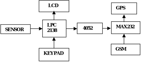
In Proposed system is divided in four different units as shown in fig1 which decrease the time required by the ambulance to reach the hospital. Following are the units
Fig 1. Overall schematic of AARS
Accident is detected by the vehicle unit and it sends the exact Latitude and Longitude co-ordinates of the accident spot to the main server.The main server search for the nearest hospital and conveys the ambulance (Ambulance unit).The main server also finds the shortest path between the accident location and the ambulance to follow the same path. The traffic control unit is used to control the traffic lights between the ambulance unit and accident location so as to reduce the time required for the ambulance to reach the accident location. The block diagram of this system is shown in the fig 1.
1.The Vehicle Unit
For implementation consider vehicle unit has been installed in every vehicle. It contains microcontroller, accelerometer, GPS and GSM module and sensors to sense the accident. On crash of the vehicle, information about accident is conveyed to the main server. This information consists of the co-ordinates of accident detected by GPS module installed in vehicle. The GPS system is used to find out current position of vehicle (latitude and longitude) which is the exact location of accident spot and gives that data to GSM module. The accident location is then conveyed to the main server unit that houses the database of all the nearby hospitals and sends an ambulance to the accident spot. This information to the main server is conveyed by GSM module. The location information is given to ambulance which helps it to reach the accident location immediately to save the casualties.
Fig 2 The block schematic of the vehicle unit.
2. The Main Server Unit
Server unit is the heart of the proposed system. Practically, the Server unit contains all the database of all the nearby hospitals in order to send an ambulance to the accident spot. It is conveyed by the GPS and GSM module installed in vehicle unit about the message informing and accident location. Server unit has many tasks to perform. we can list down those tasks as:-
Ambulance unit
Vehicle unit
Traffic control unit Main server
Sensors
KEYPAD 16x2 LCD
ATME GA32
4052 switchi ng IC
GSM
Fig 3 The block schematic of main server unit
1. Getting GPS co-ordinates from the vehicle unit. These units are communicated to the server unit using GSM unit in vehicle unit.
2. Communicating to nearest hospital
3. Controlling the signal post on the shortest path.
On the occurrence of accident, the vehicle unit instantly sends the GPS co-ordinates of the location to server unit. Our server unit will already have the locations of all the nearby ambulances. At that point of time from the accident location the server unit looks for the nearest ambulance which contains the details of all free and busy ambulances. Comparison of distance between all the nearby ambulances is being done from the accident location. The ambulance with shortest path is guided to the accident location.
3.The Ambulance Unit
Fig 3 The block schematic of ambulance unit
The ambulance unit is one of the complex units of the system. Mainly ambulance unit contains GPS and GSM module for getting GPS co-ordinates, a RF Module for communication with the traffic control unit. The ambulance unit also evaluates basic parameters of the patient so as to reduce time for diagnosis process after reaching the hospital. The vital parameters monitored by ambulance unit are heart rate and body temperature. Different sensors are used for measuring heart rate and body temperature of the patient. A report of this diagnosis is communicated to the nearest hospital. These sensors act as a input to the controlling unit of ambulance unit. An ARM7 controller is used to control all operations of ambulance unit. Another important task performed by ambulance unit is using RF module so that the ambulance gets the desired location in shortest possible time. Both traffic control unit and ambulance unit has RF module. In this way the signal posts are manipulated to get a break free path for the ambulance. Fig shows block schematic of ambulance unit for better understanding. The ambulance unit has a RF transmitter and the traffic control unit has a RF receiver. The RF transmitter on the ambulance will communicate with the RF receiver of the traffic control unit. The main server communicates the traffic unit with the shortest path to the hospital. Without any overcrowding ambulance will get a clear path all along its way to the hospital.
4. Traffic control unit
Traffic control unit is mainly responsible for managing the signal posts in the path of ambulance. The block representation of the traffic control unit can be seen in fig. The controller is connected to both RF module and signal posts, RF module acts as input where as signal posts are output .The RF id card reader reads the RF tag .This tag is
LPC 2138 SENSOR
LCD
KEYPAD
4052
GPS
GSM MAX232 4052
switching IC MAX 232
GSM
AT89C51
communicated to traffic control unit via RF module. The controller receives the id and then in turn enables the signal post tagged to that id to go green. In this way, whenever the ambulance approaches the signal post. The post goes green. Microcontroller 89C51 is used to control all operations of the traffic control unit. Controller passes signals to the traffic signals and accordingly they turn green. In this way the signals in the shortest path to the hospital is cleared for the ambulance reaches the hospital in time.
Fig 5 The block schematic of traffic control unit.
III.COMPONENTSUSEDINPROPOSEDSYSTEM
An effective solution for the proposed system is to rescue the accident sufferer and cautiously carrying him to the abreast hospital. Components which are mainly take part in proposed system are as follows:
1. ATmega32 microcontroller:
For controlling purpose in the vehicle unit it is used. Sensors are the inputs in this unit and result is displayed on the LCD.
2. Accelerometer (ADXL335):
It is a sensor to check for occurrence of the accident. As accelerometer co-ordinates varies the vehicle is tilted to accident.
3.Vibration sensor: (PUSH to ON SWITCH):
It is used as a sensor to check for the occurrence of the accident. Switch changes its state when vehicle is hit during accident.
4.AT89C51 Microcontroller:
It is used to control all operations of server unit such as getting GPS co-ordinates, informing the same to the traffic control unit, ambulance unit etc.
5.ARM Microcontroller (LPC 2138):
It is a 60 MHz microcontroller used in ambulance unit to control its operations such as fetching GPS co-ordinates , RF communication with traffic control unit, etc.
6.GSM Module(SIM900):
GSM Module is used for communicating the GPS co-ordinates to the server unit. 7.LCD 16*2 Display:
It is used for display purpose to make the proposed system user friendly.
IV.SIMULATION RESULTS
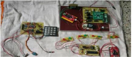
The actual setup of the proposed system is shown below in Fig 6. The setup is connected to a regulated power supply. The figure shows different units for the proposed system.
Fig 6. Actual setup of the proposed system RF
MODULE
MAX 232
89C51
Traffic control unit controlling the traffic signals is shown in below Fig 7.It shows one of the signal goes green as RF module detects ambulance near that signal.
Fig 7. Traffic control unit displaying traffic signals
The vehicle unit is shown in below fig 8.It displays sensors used for detection of accident. Sensors are connected to ATmega32 ports and then microcontroller informs the server unit about the occurrence of accident.
Fig 8. Vehicle unit with accident detection sensors
Fig 9 shows the ambulance unit showing RF module and RF card reader. It uses ARM7 controller for controlling all operations of ambulance unit.
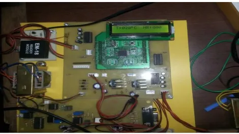
The LCD displays the detection of accident. It also gets GPS co-ordinates from GPS module and displays them on LCD display. We have set accelerometer co-ordinates as Xmin = Ymin = 270 and Xmax = Y max = 380. This range specifies the normal position of vehicle. If co-ordinates go out of range, then we say that accident has occurred. It also shows the temperature. It can be seen in below Fig 10.
Fig10 Displays GPS co-ordinates after accident detection and temperature.
Figure 11 shows the latitude and longitude of ambulance 1 through GPS also latitude and longitude of ambulance 2. Then as the co ordinates traced then main server will search for the nearest ambulance. Whichever ambulance is nearby it will convey the location of accident to that ambulance. As the ambulance reached to the accident spot it will take the victim and along with will check for the green signal.
Fig 11 Displays location of ambulance 1 and 2.
REFERENCES
[1] Sotiris Pavlopoulos, EfthyvoulosKyriacou,” A Novel Emergency Telemedicine System Based on Wireless Communication Technology— Ambulance”, ieee transactions on information technology in biomedicine, vol. 2, no. 4, December 1998, pp. 261-267.
[2] Manuel Fogue, PiedadGarrido, Member, IEEE, Francisco J. Martinez, Member, IEEE, Juan-Carlos Cano, Carlos T. Calafate, and Pietro Manzoni, Member, IEEE,” A System for Automatic Notification and Severity Estimation of Automotive Accidents” IEEE TRANSACTIONS ON MOBILE COMPUTING, VOL. 13, NO. 5, MAY 2014
[3] RajeshwariSundar, SanthoshsHebbar, and VaraprasadGolla, “Implementing Intelligent Traffic Control System for Congestion Control, Ambulance Clearance, and Stolen Vehicle Detection” IEEE SENSORS JOURNAL, VOL. 15, NO. 2, FEBRUARY 2015
[4] Automatic accident detection and ambulance rescue with intelligent traffic light system by Mr.S.Iyyappan , Mr.V.Nandagopal International Journal of Advanced Research in Electrical, Electronics and Instrumentation Engineering Vol. 2, Issue 4, April 2013
[5] Intelligent Accident-Detection And Ambulance- Rescue System by Bhandari Prachi, Dalvi Kasturi, Chopade Priyanka, INTERNATIONAL JOURNAL OF SCIENTIFIC & TECHNOLOGY RESEARCH VOLUME 3, ISSUE 6, JUNE 2014
[6] Sotiris Pavlopoulos, EfthyvoulosKyriacou, Alexis Berler, Spyros Dembeyiotis,and DimitrisKoutsouris, Senior Member, IEEE,” A Novel Emergency Telemedicine System Based on Wireless Communication Technology—AMBULANCE” IEEE TRANSACTIONS ON INFORMATION TECHNOLOGY IN BIOMEDICINE, VOL. 2, NO. 4, DECEMBER 1998
[7] Xiaolin Lu, Develop Web GIS Based Intelligent Transportation Application Systems with Web Service Technology, Proceedings of International Conference on ITS Telecommunications, 2006.
[8] Seokcheon Lee , Role of Parallelism in Ambulance Dispatching”’ IEEE TRANSACTIONS ON SYSTEMS,MAN, AND CYBERNETICS: SYSTEMS, VOL. 44, NO. 8, AUGUST 2014 pp 1113-1122