COMBUSTION OF MUNICIPAL SOLID WASTE USING STANDPIPES AIR DISTRIBUTORS
ANWAR BIN JOHARI
A thesis submitted in fulfilment o f the requirements for the award o f the degree of Doctor of Philosophy (Chemical Engineering)
Faculty of Chemical and Natural Resources Engineering Universiti Teknologi Malaysia
Dedicated to human race;
“Look towards those who rank below you (so that you may get used to being thankful) and do not look who rank above you, lest you should despise the favours of Allah upon you”
A C K N O W LE D G M EN T
I would like to express my sincere thanks to Associate Prof. Dr. Mohd. Rozainee Taib o f Department o f Chemical Engineering, Faculty o f Chemical and Natural Resources Engineering, Universiti Teknologi Malaysia, for his continuous guidance, assistance and support throughout the course of the research.
A BSTRA CT
A B STR A K
C H A P T E R T IT L E PA G E
TITLE PAGE i
DECLARATION ii
DEDICATION iii
ACKNOWLEDGEMENT iv
ABSTRACT v
ABSTRAK vi
TABLE OF CONTENTS vii
LIST OF TABLES xiii
LIST OF FIGURES xvi
LIST OF SYMBOLS xviii
APPENDICES xxiii
1 IN T R O D U C TIO N 1
1.1 Introduction 1
1.2 Research Background 1
1.2.1 Selection o f Fuel for Combustor 2 1.2.2 Selection of Thermal Treatment Methods 8
1.2.3 Selection o f Combustion Technology 9
1.3 Justification of the Research 13
1.4 Objectives o f the Research 16
1.5 Scope of the Study 17
1.6 Thesis layout 18
2 L IT E R A T U R E R E V IE W 19
2.1 Introduction 19
2.2 Fluidization Concept 19
2.3 Physical Properties of Particles 23
2.3.1 Bed Voidage (e) 23
2.3.2 Particle Sphericity (<p) 24
2.3.3 The Geldart Classification of Particles 24
2.4 Bubble Dynamics 26
2.4.1 Bubble Rising Velocity and Bubble Size 27
2.5 Entrainment and Elutriation 29
2.6 Fluidized Bed Air Distributors 33
2.6.1 Current Research W ork on the Standpipes Air
Distributors 35
2.7 Combustion Theory 36
2.7.1 M oisture Evaporation 37
2.7.2 De-volatilization/pyrolysis 37
2.7.3 Char Combustion 41
2.8 Combustion Technology o f Municipal Solid Waste 42 2.9 Combustion of Solid Waste in a Fluidized Bed 44 2.9.1 Combustion o f Biomass in a Fluidized Bed 47 2.9.2 Combustion o f Coal in a Fluidized Bed 49 2.9.3 Combustion o f Refuse Derived Fuel (RDF) in a
Fluidized Bed 50
2.9.4 Combustion o f High Moisture Content Waste
in a Fluidized Bed 52
3 M E T H O D O L O G Y 56
3.1 Introduction 56
3.2 Scope o f Research Activities 56
3.3 Formulation o f the Simulated Municipal Solid Wastes
and its Chemical and Physical Characterization 58
3.3.1 Analytical Tests 58
3.4 M easurement o f the Physical Properties o f Sand 61 3.5 Geometrical Design o f a Standpipe Air Distributor 61
3.5.1 Single Orifice Study 63
3.5.2 Orifice Distance Study 64
3.5.3 Pipe Distance Study 65
3.6 Hydrodynamic o f Circular and Rectangular Columns
(Small Scale) 66
3.6.1 Circular Hydrodynamic Studies (CHS) 68 3.6.2 Rectangular Hydrodynamic Studies (RHS) 75
3.6.3 Combustor Selection Procedures 76
3.7 Hydrodynamics of Bigger Scale Rectangular Column 77
3.7.1 Equal Flow Studies 80
3.7.2 Centre High Studies (CH) 81
3.7.3 Two-Side High Studies (TSH) 81
3.7.4 One-Side High Studies (OSH) 82
3.7.5 Sample Preparation 83
3.8 Calorific Value of Solid Waste 83
3.9 Combustion of Simulated Municipal Solid Waste in a
Rectangular Column 85
3.9.1 Sample Preparation and Experimental Set-up 88 3.9.2 Temperature, Emission M easurement and
Data Logging System 90
3.9.3 Combustion Calculation for the Simulated
Municipal Solid Waste Combustion Studies 95 3.9.4 Calculation of Adiabatic Flame Temperature 97
3.9.6 Study on Effect of Fluidization Numbers on the Combustion of Simulated Municipal
Solid Waste 102
3.9.7 Study on Effect o f Air Factor (AF) 106
3.9.8 Bed Pre-heating 108
3.10 Combustion of Municipal Solid Waste in a Rectangular
Column 110
3.10.1 Study on the Effect of Different Fluidization Numbers (Primary Air) on the Sustainability
of the Combustion o f Municipal Solid Waste 113 3.10.2 Calculation o f Combustion Quality and Carbon
Utilization Efficiency 115
3.10.3 Study on the Effect o f Secondary Air on the
Combustion o f Municipal Solid Waste 117 3.11 Combustion o f Municipal Solid Waste in a Circular
Fluidized Bed 118
3.11.1 Experimental Set-up 120
4 R ESU LTS AND D ISCU SSIO N 123
4.1 Introduction 123
4.2 Effect of Sand Physical Properties on the
Minimum Fluidization Velocity 124
4.3 Effect of Air Distributor Geometrical Design
on the Fluidization Behaviour 126
4.3.1 Effect o f Orifice Diameter 126
4.3.2 Effect o f Orifice Distance 129
4.3.3 Effect o f Pipe Distance 131
4.4 Summary - Geometrical Design o f Standpipes
Air Distributor 132
4.5 Hydrodynamic Studies o f Circular and Rectangular
Columns (Small Scale) 133
4.6 Hydrodynamics o f Bigger Scale Rectangular Column 149 4.6.1 Effect o f Equal Air Flow (EF) Strategy 150 4.6.2 Effect o f Centre High Air Flow (CH) Strategy 153 4.6.3 Effect o f One Side High Air Flow (OSH) Strategy 156 4.6.4 Effect o f Two Side High Air Flow (TSH) Strategy 158
4.7 Summary - Hydrodynamic Studies 161
4.8 Combustion Studies in a Fluidized Bed 165 4.8.1 Properties o f Simulated Municipal Solid Waste 165 4.9 Combustion Study o f Simulated Municipal Solid Waste 167
4.9.1 Effect of Fluidization Number on the Combustion of the Simulated Municipal Solid Waste 168 4.9.2 Adiabatic Flame Temperature and Thermal
Efficiency o f Simulated Municipal Solid Waste 173 4.9.3 Effect o f Air Factor on the Combustion of
Simulated Municipal Solid Waste 177
4.9.4 Overall Thermal Efficiency at Different
Air Factors 180
4.9.5 Optimum Throughput Rate o f Simulated Municipal Solid Waste Rectangular Fluidized
Bed Combustor 182
4.10 Combustion Study Using Municipal Solid W aste 183 4.10.1 Effect o f Fluidization Number on the Combustion
of the Municipal Solid W aste 184
4.10.2 Overall Thermal Efficiency r m and Carbon Utilization Efficiency rjcu o f Municipal Solid
Waste Combustion 188
4.10.3 Gases Emission in the Combustion of Municipal Solid Waste at 5 Umf and AF = 0.8 190 4.10.4 Effect o f Secondary Air on the Combustion of
Municipal Solid Waste 194
4.10.5 Gas Emission Yield at Different Total
4.10.6 Combustion Quality Efficiency 200 4.11 Combustion of Municipal Solid Waste in a Circular
Fluidized Bed 202
4.12 Comparison of Bed Combustion Profiles of Municipal
Solid Waste in a Rectangular and Circular Fluidized Bed 205 4.12.1 Bed Temperature Profile o f Circular and
4.12.2 Rectangular Fluidized Bed 205
4.13 Summary - Combustion Studies 207
5 C O N C LU SIO N S AND R EC O M M EN D A TIO N S 212
5.1 Conclusions 212
5.2 Recommendations for Future Study 214
R E FE R E N C E S 217
TA BLE NO. T IT L E PA G E 1.1 Waste components o f municipal solid waste for Thailand and the UK 4 1.2 Compositions o f municipal solid waste generated from residential
medium income in Kuala Lumpur 5
1.3 Composition o f simulated municipal solid waste 6
1.4 Heat content o f municipal solid waste 8
1.5 Investment cost o f small cogeneration plants in Finland 12 2.1 Correlations for the estimation o f bubble diameter 29 2.2 Composition o f volatile and fixed carbon for selected fuels 46
2.3 RDF fuel analyses 51
3.1 Column shape and size 68
3.2 Dimensions o f air distributors in the CHS studies 70 3.3 Flow rates at 1 Umf for different sand sizes for the CHS 71
3.4 Grading system for the CHS study 71
3.5 Flow rates at 1 Umf for different sand sizes for the RHS 76 3.6 Experimental set-up for the Centre High Studies 81 3.7 Experimental set-up for the Two-Side High Studies 82 3.8 Experimental set-up for the One Side High Studies 82
3.9 Samples used in big rectangular study 83
3.10 Design and operating parameters for the combustion studies 87 3.11 Composition o f simulated municipal solid waste 88 3.12 Tapped holes locations for online monitoring system 92 3.13 General specification o f SWG 300-1 gas analyzer 95 3.14 Measuring ranges and accuracy as given by the manufacturer 95 3.15 Flow rate o f incoming air for various fluidizing numbers 103
3.16 Air requirement for fluidization at different fluidizing numbers 104 3.17 Air distribution in each air distributor at different fluidization numbers 105 3.18 Feed input needed at different fluidization numbers 106 3.19 F eed input needed at 5 Umf at different air factors 107 3.20 Flow o f incoming air into each air distributor pipe 107 3.21 Design and operating parameters for the combustion o f MSW 111 3.22 Operating parameters for the combustion o f municipal solid waste at
5, 6 and 7 Umf 114
3.23 Operating parameters on the study o f the effect o f the secondary air 118 3.24 Selected operating parameters for circular and rectangular fluidized bed 119 3.25 Operating parameters o f circular fluidized bed studies 119
3.26 Position o f thermocouple probes 120
4.1 Sand physical properties 124
4.2 Umf for both observation and calculated from correlations 125 4.3 Effect o f stand pipe orifice diameter on the fluidizing behaviour in a
single orifice study 129
4.4 Effect o f orifice distance 130
4.5 Effect o f pipe distance on the bubbling behaviours 131 4.6 Final distributor design dimensions for CHS and RHS 132 4.7 Fluidization quality for Sand Sieve No. 10/20 at different fluidization
numbers at 1 Dc and 1 W 134
4.8 Fluidization quality for Sand Sieve No. 20/30 at different fluidization
numbers at 1 Dc and 1 W 135
4.9 Fluidization quality for Sand Sieve No. 30/60 at different fluidization
numbers at 1 Dc and 1 W 135
4.10 Grade point at different aspect ratios for Sand Sieve No. 10/20 140 4.11 Grade point at different aspect ratios for Sand Sieve No. 20/30 142 4.12 Grade point at different aspect ratios for Sand Sieve No. 30/60 144 4.13 The onset o f slugging for circular and rectangular columns using
different mean sand sizes 148
4.14 Grade point for samples at different fluidization numbers using
4.15 Grade point for samples at different fluidization numbers using
Centre High Flow strategy 154
4.16 Grade point for samples at different fluidization numbers using
One-Side High Flow strategy 157
4.17 Grade point for samples at different fluidization numbers using
Two-Side High Flow strategy 160
4.18 Summary o f best operating conditions for CHS and RHS 163
4.19 Properties o f SMSW and MSW 166
4.20 Average temperature profile in bed (T1), bed surface (T2) and
freeboard (T3, T4, T5) at different fluidization numbers at AF = 1 168 4.21 Adiabatic flame, highest and average temperatures at Location T4 173 4.22 Percentage heat loss at different fluidization numbers 175 4.23 Thermal efficiency o f the simulated municipal solid waste at
5, 6 and 7 Umf 176
4.24 Average temperature profile at various temperature probe locations
operating at 5 Umf at different air factors 179
4.25 Overall thermal efficiency at different air factors operated at 5 Umf 181
4.26 Throughput rate at fluidization number 5 183
4.27 Average temperature profile at AF = 0.8 at different fluidization
numbers for the combustion o f municipal solid waste 186 4.28 Overall thermal and carbon utilization efficiency o f municipal
solid waste operated at 5 and 6 Umf and Air Factor = 0.8 189 4.29 Secondary air flow rate at different Total Air Factor 194 4.30 Average bed (T1), surface (T2) and freeboard (T3, T4, T5, T6)
conducted at secondary air AF = 0 197
4.31 Average bed surface (T2) and freeboard temperature (T3, T4, T5, T6)
at different secondary Air Factors 198
4.32 Product gases at different Total Air Factors 199
FIG U R E NO. T IT L E PA G E
1.1 Solid waste generation in states in Malaysia 3
1.2 Schematic o f Bubbling and Circulating Fluidized Bed Combustors 12
2.1 Fluidization states 20
2.2 A powder classification diagram by Geldart 25
2.3 Interchange o f solids and the rising bubble 26
2.4 Chart for determining the terminal velocity falling through fluids 31
2.5 TDH in a bubbling fluidized bed 32
2.6 Processes occurring during incineration 36
2.7 Schematic diagram o f mass burn incinerator with travelling grate 43 2.8 Typical municipal solid waste sorting for RDF production 44
3.1 Single orifice study 64
3.2 Orifice distance study 65
3.3 Experimental-layout in determining the optimum pipe distance 66
3.4 Test rig for CHS 69
3.5 Layout o f standpipe for air distributor (20 cm internal diameter) 70
3.6 Mixing behaviour at selected grade point 74
3.7 Steps for determining the suitable operating conditions for CHS 74 3.8 RHS experimental layout with three air distributors 75
3.9 Procedure for column type selection 77
3.10 Big scale rectangular experimental rig with three air distributors 80 3.11 General overview o f the research work on the combustion o f the
simulated municipal solid waste 85
3.12 Air distributors o f the rectangular fluidized bed 89 3.13 Photograph of rectangular fluidized bed combustor 90
3.14 Schematic o f the experimental layout o f rectangular fluidized
bed combustor 91
3.15 SWG 300-1 gas analyzer 92
3.16 Oxygen measurement principle 94
3.17 Schematic diagram o f heat balance o f a fluidized bed 100
3.18 Pre-drying o f palm shell 108
3.19 Heated fluidized bed at 7000C 109
3.20 Experimental procedures in the combustion o f municipal solid waste 110
3.21 Municipal solid waste dried-up area 112
3.22 Packed municipal solid wastes for combustion studies 113 3.23 Schematic diagram for the determination o f carbon utilization
Efficiency 115
3.24 Experimental layout o f circular fluidized bed combustor 121 3.25 Photograph o f circular fluidized bed combustor 122 4.1 Stagnant and mixing zones in the Perspex column o f fluidized bed
single orifice study 128
4.2 Solids slugs observed at 1.5 Dc, 3 Umf and using Sand Sieve No. 20/30 147 4.3 Circulation and dead zones in rectangular column 151 4.4 Mixing and sand circulation pattern in Centre High Flow strategy 153
4.5 Flow pattern in One Side High strategy 157
4.6 Mixing behaviour by Two-Side High Flow strategy 159
4.7 Bed temperature at different fluidization numbers 171 4.8 Effect o f air factors on bed temperature profile at 5 Umf 178 4.9 Bed temperature (T1) at 5, 6 and 7 Umf using municipal solid waste
in a rectangular fluidized bed combustor 185
4.10 Temperature profile at 5 Umf and AF=0.8 for the combustion of
municipal solid waste in a rectangular fluidized bed combustor 188 4.11 Temperature and product gas profile at 5 Umf and AF = 0.8 191 4.12 Effect o f secondary air on the bed temperature profile at 5 Umf and
primary air factor 0.8 195
4.13 Temperature profile of bed and freeboard operating at 5 Umf and
Total Air Factor = 1.4 203
LIST OF SYMBOLS
2 A , A Cross-sectional area o f bed, (m ) A Area o f distributor plate per hole, (m )
A r Archimedes number, A r = P p—P f ^ m (dimensionless) V f
B i Biot number (dimensionless) CPa Average heat capacity o f air (J/g0C)
CPv Average heat capacity o f volatiles (J/g0C) Cp^ Average heat capacity o f char and ash (J/g0C)
CPds Average heat capacity o f dry waste (J/g0C) CPwv Average heat capacity o f water vapour (J/g0C)
CxH y Hydrocarbon
D c Column diameter, (m) Db, ^ Bubble diameter, (m)
Dg Binary molecular diffusion coefficient o f oxygen in air, (m /s) d bo Initial bubble formed near the bottom o f the bed, (m)
d t Diameter o f the spherical fuel particle, (m) dm, d p Mean particle diameter (m), particle diameter (m) d t Bed diameter, (m)
g P f (p3 - p f )' d „ Dimensionless particle size, d „ = d sph
g Conversion factor, A
H Specific enthalpy o f the ith component at 250C, (kJ/kg) ( W
h Heat transfer coefficient.
k Thermal conductivity, v (
_W_
v mKL mf Height o f bed at minimum fluidization, (m) L p Pyrolysis endothermicity, (kJ/kg)
M Mass o f solid in bed, (kg) M a Mass flow rate o f air (g/min)
M ca Mass flow rate o f residual char and ash (g/min) M ds Mass flow rate o f dry waste (g/min)
M f Mass flow rate o f fuel (g/min) M v Mass flow rate o f volatiles (g/min) M w Mass flow rate o f water (g/min) nd Total number o f orifices
n Moles o f the ith component in the feed or product p s Partial pressure o f oxygen at the carbon surface, (atm) Qrad Radiative heat loss (W)
( W
q, q Heat flux I —- I, heat liberated (J/g) m2
Re Reynolds number, Re = ( p u p } Vf
(dimensionless)
Ta, Ta Inlet air temperature (0C), temperature o f flame (K)
r o Temperature o f particle (K), temperature o f the surroundings (K)
Tb Bed temperature (0C)
Tad Adiabatic flame temperature, (0C)
De-volatilization time, (s) Burn-out time, (s)
( m Fluidization velocity, I —
U, Bubbles velocity in a bubbling fluidized bed, I —m
br Single bubble velocity, I —m
U
0,u
0 Fluidization velocity at the distributor, I —m
U mf, u mf
U t, ut
Dimensionless gas velocity, u« = ut P f g v { p s - P f)
b0
Distance above the distributor, (m) Height o f initial bubble formation, (m)
AP Pressure drop across the bed, I — -m
( k J Heat o f combustion o f the fuel at reference temperature 25 C, t
mol A
A H Heat o f vaporization o f water at 25 C, 0 ( t k J mol
s
s
s
G reek L etters
a Thermal diffusivity (a = kpP1Cp1)
X Amount o f heat required to raise the moisture from ambient conditions to the boiling point and to evaporate the moisture, (J/g)
W
o _____
a Stefan-Boltzmann constant (5.67x10' m2k ) s , s mf Bed voidage, bed voidage at minimum fluidization s m Emissivity o f the bed surface, (dimensionless) 0S particle sphericity, (dimensionless)
l f , jug fluid viscosity ( — | , gas viscosity, ( — |
f g l ms J l ms J
p b Bulk density, ( |
I m J
p c Carbon density o f a char particle, | | l m J
p Density o f fluidization gas, ( k g | I m J
p Particle density, ( k g | I m J
p f Fluid density ( k g | , gas density ( |
l m J l m J
A bbreviation
2D Two-dimensional
3D Three-dimensional
AF Air Factor
ASEAN Association o f South East Asian Nations BFB Bubbling Fluidized Bed
CH Centre High
CFB Circulating Fluidized Bed CHS Circular Hydrodynamic Studies
EF Equal Flow
GI Galvanized Iron
HHV High Heating Value, (MJ/kg) ITA Investment Tax Allowance LHV Lower Heating Value, (MJ/kg) LDPE Low Density Polyethylene
LPM Litre Per Minute
MSW Municipal Solid Waste
OSH One Side High
PS Pioneer Status
PAH Polycyclic aromatic hydrocarbon
ppm part per million
RC - 1 Rectangular column - 1 RC - 2 Rectangular column - 2
RDF Refused Derived Fuel
RHS Rectangular Hydrodynamic Studies SEM Scanning Electron Microscope
SPP Small Power Producers
SREP Small Renewable Energy Programme TDH Transport Disengaging Height
TSH Two Side High
A PPEN D IC ES
A PPEN D IX T IT L E PA G E
A Formulation o f the Simulated Municipal Solid Waste 225
B Calculation o f Adiabatic Flame Temperature 234
C Calculation o f Thermal Efficiency 242
IN T R O D U C TIO N
1.1 In tro d u ctio n
This chapter discusses the thermal treatment o f the municipal solid waste in a fluidized bed combustor. It also discusses the background o f the research activities, selection and justification for the proposed study. B rief description on the reason for the utilization o f fluidized bed for waste incineration is included and focus is given on the Malaysian energy scenario. The objectives of the research and the scope of work are also pointed out.
1.2 R esearch B ackground
Fuel for combustor may vary as it depends on the purpose o f the burning itself. In the case o f municipal solid waste, the waste itself is regarded as a fuel. Ruth (1998) has given a thorough review on the combustion technology using municipal solid waste as its feed. Another source o f fuel is the biomass waste and becomes one o f the promising sources o f fuels for energy generation. Experimental investigation on the combustion o f biomass in a pilot scale fluidized bed has been carried out by Saenger et al. (2001) and Natarajan et al. (1997) on the combustion o f coffee husk and Armesto et al. (2002) on the combustion and gasification o f rice husks. These two sources o f fuels are readily available and many research and commercial activities have been done especially on the aspect o f energy conservation via the integrated power plant operation system. Coal as a fuel has been another source of energy generation as commonly practised decades ago. Extensive research activities on the combustion o f coal are still being carried out. Saxena et al. (1997) used a fluidized bed o f 0.154 m in diameter and an overall height o f 3.5 m on their research on the combustion o f coal.
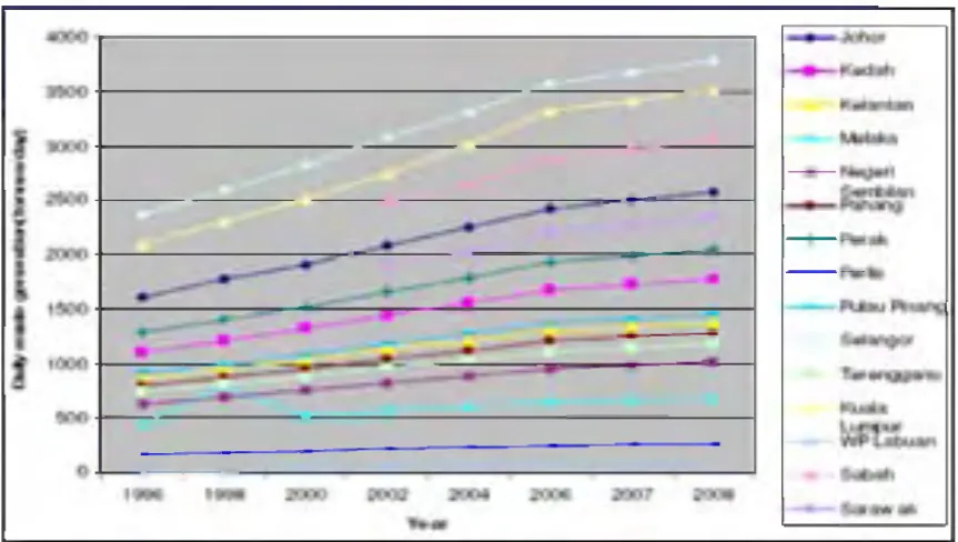
Looking into Malaysian perspective, municipal solid wastes are abundant and cause a challenging effort for the authorities to dispose it off. As a matter o f fact, the increase in municipal solid waste is an indication o f the progress o f Malaysia towards developed nation. Solid waste generation in major urban area in peninsular M alaysia is shown in Figure 1.1.
Figure 1.1: Solid waste generation in states in Malaysia (Agamuthu, 2008)
Data clearly show an increment in waste generation in states in Malaysia, so does the problem of disposing it. Currently the most widely used method of waste disposal in Malaysia is land-filling. However, with tremendous increment in waste generation annually, the Malaysian government has looked into several alternatives in reducing the disposal problem such with the possible use of thermal treatment method.
solid waste components has been used in a fluidized bed combustor (Piao et al., 2000; Hernandez-Atonal et al., 2007).
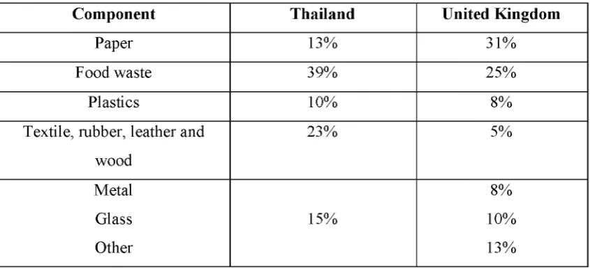
The compositions o f the municipal solid waste vary with geographical location, social and economic status. For example, the amount o f moisture in municipal solid waste is low in industrialised countries, whereas wastes in developing countries especially in ASEAN region contain high moisture content. Typical distribution o f components in municipal solid waste for Thailand and the United Kingdom is shown in Table 1.1.
T able 1.1: Waste components o f municipal solid waste for Thailand and the UK (Patumsawad and Cliffe, 2002)
C om ponent T hailand U nited K ingdom
Paper 13% 31%
Food waste 39% 25%
Plastics 10% 8%
Textile, rubber, leather and wood
23% 5%
Metal 8%
Glass 15% 10%
Other 13%
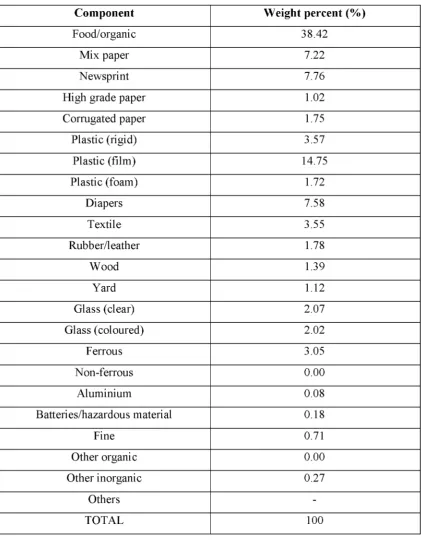
Table 1.2: Compositions o f municipal solid waste generated from residential medium income in Kuala Lumpur (Karthirvale et al., 2003)
C om ponent W eight percen t (% )
Food/organic 38.42
Mix paper 7.22
Newsprint 7.76
High grade paper 1.02
Corrugated paper 1.75
Plastic (rigid) 3.57
Plastic (film) 14.75
Plastic (foam) 1.72
Diapers 7.58
Textile 3.55
Rubber/leather 1.78
Wood 1.39
Yard 1.12
Glass (clear) 2.07
G lass(coloured) 2.02
Ferrous 3.05
Non-ferrous 0.00
Aluminium 0.08
Batteries/hazardous material 0.18
Fine 0.71
Other organic 0.00
Other inorganic 0.27
Others
-TOTAL 100
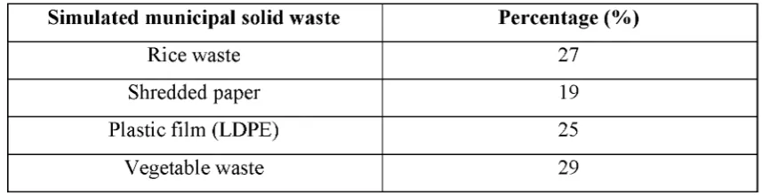
the fluidized bed combustion o f municipal solid waste will be based on findings from the combustion o f the simulated municipal solid waste. The formulation o f the simulated municipal solid waste used in the current research activities is based on the data gathered from the municipal solid waste characteristics study conducted in Kuala Lumpur (Rozainee, 2001). The simulated municipal solid waste is made of four major categories; namely, food waste, plastics, paper and vegetable wastes. Proximate analysis was conducted to investigate the simulated municipal solid waste compositions in terms o f four constituents; namely moisture content, volatile matter, ash and fixed carbon. Ultimate analysis was carried out to determine the chemical elements that make up the sample namely carbon content, hydrogen content and oxygen content. The percentage compositions o f these waste categories are shown in Table 1.3. Appendix A shows the detail calculation and formulation o f simulated municipal solid wastes.
Table 1.3: Compositions o f simulated municipal solid waste Sim ulated m unicipal solid w aste P ercentage (% )
Rice waste 27
Shredded paper 19
Plastic film (LDPE) 25
Vegetable waste 29
stages: (i) mixing the components, (ii) size reduction by shredding, (iii) compaction into cylindrical pellets o f 2.5 cm diameter and approximated length o f 5 cm.
Yang et al. (2003) presented another technique for the formulation o f the simulated municipal solid waste. The major fuel in the simulated waste consists of cardboard and vegetable and the weight ratio between the cardboard and vegetable was 1.85:1 which is in accordance to the ratio between paper and food content in a typical United Kingdom municipal solid waste. Knowing the waste characteristics enable researchers to simulate the feed into the combustor. The majority o f the combustible materials in the municipal solid waste derived from paper and plastics. These materials if it were to be separated or sorted out from the bulk o f the municipal waste could be used as a potential fuel for the combustor as they yield high calorific values. Salvador et al. (2004) studied the combustion o f substitution fuels that were made from compressed mixes o f cardboard and polyethylene. These two materials represent the two classical classes o f waste components.
Municipal solid waste disposal has always been seen as a burden but with good solid waste management, the municipal solid waste is actually an asset. Having known the waste compositions in the municipal solid waste enables the separation of combustible and incombustibles prior to the combustion o f the wastes. The municipal solid waste could be turned into resources o f energy and electricity generation through the implementation o f the state o f the art thermal decomposition method such as demonstrated by the fluidized bed combustion or gasification system.
waste in one country will be different from that o f another. Table 1.4 shows the heat content o f municipal solid waste in Thailand and United Kingdom.
Table 1.4: Heat content o f municipal solid waste H igh H eating V alue
(HHV)
M J/k g (as received) M J/k g (dry basis)
Thailand 6.49 MJ/kg* 15.59 MJ/kg*
United Kingdom 10.25 MJ/kg* 15.0 MJ/kg*
* Data from Patumsawad and Cliffe, (2002).
Knowledge o f the physical characteristics and chemical composition of municipal solid waste are crucial as these parameters influence the overall behaviour o f the combustion system. For example, differences in properties o f coal and municipal result in differences in the combustion characteristics o f these fuels and in turn affect the type o f combustion equipment. In particular, the most important fuel properties are the size o f the fuel particles and the fuel composition. The size o f fuel particle affects the length o f time required for its combustion. Municipal solid waste for example comprises o f extremely variable sizes and shapes, thus longer residence times are required to completely burn the waste.
1.2.2 Selection of T h erm al T rea tm e n t M ethods
Normally pyrolysis reaction temperature is carefully controlled at around 5000C. Much o f the present interest in pyrolysis is focused on the liquid (tar) production. However, as pyrolysis liquid contains organic materials and water, many are reported to contain polycyclic aromatic hydrocarbon (PAH), some o f which have shown to be carcinogenic. Horne and W illiams (1996) reported that the pyrolysis liquid o f mixed wood contains both monocyclic hydrocarbon such as benzene, toluene and dimethyl and ethylbenzene and polycyclic aromatic hydrocarbons. On the shorter note, by assessing the pros and cons o f pyrolysis technique, the idea o f using this method into the present research activities is unrealistic since pyrolysis technique is not intended for the mass reduction o f solid waste. Hence, other techniques such as combustion or gasification will be the best bet for solving the problems o f municipal solid waste disposal.
Combustion and gasification technology are two thermo-chemical treatments that have gained much interest in recent years. These processes offer a more realistic approach in dealing with the tremendous increase in the municipal solid waste in Malaysia. In a gasification process, waste is converted to a combustible gas mixture by partial oxidation (starved air condition) o f waste at high temperature, typically in the range o f 800 - 9000C. The main gaseous components are carbon monoxide and hydrogen. Combustion process on the other hand requires excess air, thus producing carbon dioxide and water. These two processes carried out in a fluidized bed combustor offer upstream flexibility (biomass, coal and municipal solid waste) and downstream product flexibility (gaseous products) advantages.
1.2.3 Selection of C om bustion Technology
system, whereas refused derived fuel (RDF) is commonly burnt in a fluidized bed. Grate-firing systems are equipped with flat or sloping grates. The grates may either be moving or stationary in design. The moving grate system requires large operational area and not economical to be constructed ju st for the academic exercises. On the other hand, the stationary grate system is a fixed bed combustion system and even though requires less operational area and economical, the combustion behaviour o f a fixed bed and fluidized bed is different. Both grates system do not have a fluidization medium, thus, not within the scope and objectives of the current research study. Grate-firing reactors were the most versatile units in the mid 1980s.
Fluidized beds have only gained tremendous acceptance in the recent years due to several reasons. One o f them is the ability to burn various types o f fuels because it provides long fuel residence times, good contacting o f fuel and bed material with air with a relatively uniform temperature distribution inside the bed. In the fluidized bed system, the bed is first heated close to the operating temperature. The bed material, usually sand, absorbs and stores the heat, while the turbulence and mixing o f the bed keeps the temperature uniform throughout the bed. W hen waste is introduced into the fluidized bed, the high heat and mass transfer characteristics of the bed permits the rapid energy conversion at practically isothermal condition. The high surface area available in fluidized beds on which reactions could occur, result in good conversion efficiency, higher throughput and lower operating temperature. Uniform temperatures and high heating capacities o f sand permits a wide range of low-grade fuels o f even non-uniform size and varying moisture content to be converted to desired products (Natarajan et al., 1997).
wide variation o f moisture contents. The mass concentration o f fine particles is less in the BFB compared to that o f the CFB due to the lower application o f the fluidization number in the BFB. The BFB combustor operates at lower fluidization velocity, typically 1-3 m/s whereas the CFB combustor operates at higher fluidization velocity ranges from 3 - 10 m/s (Koornneef et al., 2007). As a result of the higher fluidization velocity in the CFB combustor, solids are entrained in the air flow more equally along the combustor height and the heat transfer and combustion temperature is more equally distributed with the combustor height compared to the BFB. W ith an increase in the mass load o f the elutriated fine particles, the design o f the cyclone separator would be larger in the CFB than in the BFB. Thus, increasing the investment cost o f the CFB system (Anthony, 1995). In the CFB combustor, the major portions o f the dust and unconverted carbon in the product gas are recycled to the reactor bottom through a cyclone, thus leading to high carbon conversion.
Table 1.5: Investment cost o f small cogeneration plants in Finland (Bain et al., 1998)
P lan t C apacity pow er/heat (MWe/MWt)
Type of com bustor Investm ent cost (£ M illion)
Pieks-m-ki 9/25 BFB 9.5
Kankaanp 6/16 BFB 8.0
Kuhmo 5/13 CFB 12.3
Ylivieska 5/15 BFB 8.7
Kuusamo 6/17 BFB 8.0
Lieksa 8/22 CFB 11.3
The schematic diagram o f the bubbling and circulating fluidized bed combustors is shown in Figure 1.2.
Considering the existing laboratory facilities and from the evaluation of operation, design and costs o f the BFB and CFB, the BFB combustor system is chosen for the current research work.
1.3 Justification of the R esearch
The title o f the research is ‘Design and O p eratin g P aram eters of a Fluidized Bed fo r the C om bustion of th e M unicipal Solid W aste using Standpipes A ir D istrib u to r’. As stated from the research title, the study focuses on the three major aspects, as listed below;
(i) operating parameters o f fluidized bed (ii) municipal solid waste
(iii) standpipes air distributor design
components such as glass, rubber and metal are omitted from the formulation of simulated municipal solid wastes since their compositions are low in the actual municipal solid wastes. These four components o f wastes are taken from the same source, thus, giving consistent waste characteristics in terms o f its physical and chemical compositions and moisture content. Results from the combustion o f the simulated municipal solid wastes are used as an input to the actual combustion of municipal solid wastes.
Physical and chemical characteristics o f municipal solid waste are useful in the design o f a fluidized bed combustion system. For example, information on the carbon, hydrogen and oxygen content o f the municipal solid waste or simulated municipal solid waste enables the calculation o f air requirement for the complete combustion, excess air combustion or even starved air combustion (gasification). Furthermore, enables o f estimation o f air compressor power and costing. Physical characteristic on the other hand provides information o f the waste itself such as the density o f the waste which gives an indication o f the mixing o f the waste in the fluidized bed, whether the waste float on the sand or penetrate inside the sand bed. The amount o f water in the waste gives an indication o f the burning profile in the sand bed. It shows the sustainability o f the waste combustion inside the sand bed. Volatile matter for example gives information whether the combustion is on the freeboard (region above the surface o f the sand bed) or bed combustion. Therefore, knowledge o f the municipal solid waste characterization, physical and chemical compositions are crucial as data gathered are useful for the formulation o f the simulated municipal solid waste, design and operation o f the fluidized bed.
into the fluidized bed, thus, permitting the mixing o f low density waste into the sand bed. The new design also has the advantage over those two conventional designs as it permits the disposal o f ash and other incombustibles without even dismantling the distributors. Focus on the new design includes the geometrical design such as orifice size, orifice distance and distance between each distributor pipe and their effect on the bed hydrodynamics.
The combustor shape and size are also looked into to study their effects on the fluidization. The shape o f the fluidized bed chosen for the study is o f rectangular and circular columns. The effect o f combustor shapes and sizes on the bubble formation would be observed as bubble plays a significant part in the mixing behaviour o f waste and sand. Other aspects such as the fluidizing numbers and bed height are also investigated. The sand size (fluidizing medium) also plays an important role as their properties would influence the bed hydrodynamics. The operating parameters such as air factor (ratio o f air supplied to the combustor to the stoichiometric air) and feed rate into reactor are also part or the research activities as the purpose o f the fluidized bed combustion is to maximize the feed rate o f fuel.
fluidized bed system has many advantages over the conventional land-filling operation.
The fluidized bed system can be used for biomasses and municipal solid waste (in the form o f refuse derived fuel), thus, with its broad feedstock flexibility, the fluidized bed operation is highly recommended for fast disposal o f waste. According to M a (1997) there are 2.4 million hectares under oil palm cultivation nationwide which produce a large amount o f residual waste. The timber industries generate some 12 million tonnes o f logging residues and 3 million tonnes o f wood waste a year. Paddy straw and rice husk accounted to about 3 million tonnes and 434,000 tonnes per year respectively.
Various incentives have been offered by the government to promote the renewable energy power projects (Koh and Hoi, 2002). The government can endorse Pioneer Status (PS) with full exemption for 10 years or given a Investment Tax Allowance (ITA) which is beneficial for heavy up-front capital costs.
1.4 O bjectives of the R esearch
The objectives o f this research are as follows;
(i) To design and fabricate a new air distributor for the hydrodynamics and combustion studies
(ii) To study the bed hydrodynamics o f fluidized bed under various experimental rig design
(iii) To determine the range o f operating parameters for the combustion of the simulated municipal solid waste
1.5 Scope of the Study
In order to achieve the objectives o f this research, the programme o f work have been divided into several sections as listed below;
i) The initial work consisted topics related to the fundamental concepts of fluidized bed hydrodynamics, combustion theory and waste combustion in a fluidized bed.
ii) The proximate and ultimate analyses were conducted to gives an insight into the waste physical characteristics. Methods on the formulation o f the simulated waste were presented in great details. Geometrical design and the fabrication o f air distributors were also presented.
iii) Bed hydrodynamic studies were conducted using circular and rectangular columns (small rigs) to give better understanding o f the fluidization concept. The studies involved the manipulation o f fluidizing numbers and bed height to determine the fluidization quality. Sand physical characteristics and its effect on fluidization were also examined.
iv) Up-scaling o f the smaller rig were based on the findings from the hydrodynamics studies. The study focused on the Air Flow Strategy introduced into the fluidized bed reactor.
v) The combustion o f the simulated municipal solid wastes were conducted according to the specified choice o f fluidizing numbers, bed height, sand size and air flow strategy. The ranges o f operating condition were obtained through the manipulation o f fluidizing numbers, feed throughput and the air factor. Temperature monitoring in the bed and freeboard region were used to explain the combustion profile.
1.6 Thesis layout
The thesis covers the study o f the combustion o f the simulated waste based on the following chapters;
C h a p te r 2 reviews some information on the fundamental description o f the general bed behaviour such as Geldart’s classification o f particles, minimum fluidization velocity, bubble formation, bed mixing, entrainment and elutriation of particles and transport disengaging height (TDH). The influences o f air distributors on the mixing behaviour are reviewed and this chapter also deal with the combustion of a carbonaceous material, which includes drying, de-volatilization and char combustion. Finally, the combustion o f wastes such as biomass, refused derived fuel (RDF), high water content wastes, coal in a fluidized bed are reviewed.
C h a p te r 3 concentrates on the experimental procedures in conducting the ultimate and proximate analysis. It also describes the experimental set-up and procedures during design o f standpipes air distributors, bed hydrodynamics studies and combustion tests for both simulated municipal solid waste and actual municipal solid waste.
C h a p te r 4 discusses the results obtained from the studies o f the optimum geometrical design o f the standpipes air distributors, bed hydrodynamics and combustion studies.
REFERENCES
Abelha, P., Gulyurtlu, I, Boavida, D, Seabra Barros, J., Cabrita, I., Leahy, J, Kelleher, B. and Leahy, M. (2003). Combustion o f poultry litter in a fluidised bed combustor, Fuel. 82: 687-692.
Agamuthu, P. (2008). Solid Waste: Environmental Factors and Health. EU - Asia
Solid WasteManagement Conference. Ipoh. Malaysia.
Amitin, A.V., Martyushin, I.G. and Gurevich, D.A. (1968). Dusting in the Space Above the Bed in Converters with a Fluidised Catalyst Bed. Chem. Technol. Fuels Oils. 3-4. 181.
Anthony, E.J. (1995). Fluidized Bed Combustion o f Alternative Solid Fuel; Status, Successes and Problems o f the Technology. Prog. Energy Combust. Sci. 21: 239-268.
Armesto, L, Bahillo, A., Veijonen, K., Cabanillas, A. and Otero, J. (2002). Combustion behaviour o f rice husk in a bubbling fluidized bed, Biomass and Bioenergy. 23: 171-179.
Aziz, A.A., Musa, M.N. and Salleh, M.S.M. (1995). Thermal Energy Generation using Multi-Stage Combustor for Drying o f Agriculture Produces. The 4th
ASEAN Science and Technology Week Conference. Bangkok. Thailand.
Bain, R.L., Overend, R.P. and Craig, K.R. (1998). Biomass-fired Power Generation.
Fuel Processing Technology. 54: 1-16.
Bauer, W. and Werther, J. (1982). The role o f gas distribution in fluidised bed chemical reactor design. Chem. Eng. Commun. 18: 137-147.
Belgiorno, V., De Feo, G., Della Rocca, C. And Napoli, R.M.A. (2003). Energy from gasification o f solid wastes. Waste Management. 23: 1-15.
Bolton, L.W. and Davidson, J.F. (1987). Dense Phase Circulating Fluidised Beds.
Chem. Eng. Comm. 62: 31-51.
Catipovic, N.M., Jovanovic, G.N. and Fitzgerald, T.J. (1978). Regimes o f Fluidization for Large Particles. AIChE Journal. 2. No.3.
Chakraborty, R.K. and Howard, J.R. (1981). Combustion o f char in shallow fluidised bed combustors: influence o f some design and operating parameters. Journal o f the Institute o f Energy. 48-54.
Chem, J.S. and Hayhurst, A.H. (2006). A model for the devolatilization o f a coal particle sufficiently large to be controlled by heat transfer. Combustion and Flame. 146: 553 - 571.
Colakyan, M. and Levenspiel, O. (1984). Elutriation From Fluidised Beds. Powder Technology. 38: 223-232.
Cranfield, R.R. and Geldart, D. (1974). Large Particle Fluidization. Chem. Eng. Sci.
29: 935-947.
Darton, R.C., LaNauze, R.D., Davidson, R.F. and Harrison, D. (1977). Transactions o f the Institution o f Chemical Engineers. 55: 274-280.
Davidson, J.F. and Harrison, D. (1963). Fluidized Particles. Cambridge University Press, New York.
De Luca, L, Di Felice, R. and Foscolo, P.U. (1992). Slugging behaviour o f fluidised bed o f large particles. Powder Technology. 69: 171-175.
Dimattia, D.G., Amyotte, P.R. and Hamdullahpur, F. (1997). Slugging Characteristics o f Group D Particles in Fludised Beds. The Canadian Journal o f Chemical Engineering. 75.
Ergun, S. (1952). Fluid Flow Through Packed Bed Columns. Chemical Engineering Progress. 48. No.2: 89-94.
Fagbemi, L., Khezami, L. and Capart, R. (2001). Pyrolysis products from different biomasses: Application to the thermal cracking o f tar. Applied Energy. 69: 293-306.
Felder, R. M. and Rousseau, R. W. (2000). Elementary Principles o f Chemical Processes. Third Edition. Wiley International Edition. 467-468.
Feng, D., Chen, H. and Whitings, W.B. (1985). The effect o f distributor design on fluidised bed hydrodynamic behaviour. Chem. Eng. Commun. 36: 317-332. Geldart, D. (1971). The Size and Frequency o f Bubbles in Two and Three
Dimensional Gas Fluidized Beds. Powder Technology. 4: 41.
Geldart, D. (1973). Types o f Gas Fluidisation. Powder Technology. 7: 285-292. Geldart, D. and Baeyens, J. (1985). The Design o f Distributors for Gas-Fluidised
Beds. Powder Technology. 42: 67-78.
Geldart, D., Hurt, J.M. and Wadia, P.H. (1978). Slugging in Beds o f Large Particles.
AIChE Symp. Series. 176. 74.
Geldart, G. (1973). Types o f Gas Fluidization. Powder Technology. 7: 285-292. Getti, P, Robertis, U.D., D ’Antone, S., Villani, M. and Chiellini, E. (1985). Coal
Combustion - Correlation between surface area and thermogravimetric analysis data. Fuel. 64: 950-955.
Gidaspow, D., Seo, Y.C. and Ettehadieh, B. (1983). Hydrodynamics o f Fluidization: Experimental and Theoretical Bubble Sizes in a Two-Dimensional Bed With a Jet. Chem. Eng. Commun. 22: 253-272.
Goh, Y.R., Siddal, R.G., Nasserzadeh, V., Zakaria, R, Swithenbank, J., Lawrence, N., Garrod, N., Jones, B. (1998). Mathematical Modelling o f the burning bed of a waste incinerator. Journal o f the Institute o f Energy. 71: 110-118.
Haider, A and Levenspiel, O. (1989). Drag Coefficient and Terminal Velocity of Spherical and Non-Spherical Particles. Powder Technology. 58: 63-70.
Hamdullahpur, F. and MacKay, G.D.M. (1986). Two-Phase Flow Behaviour in the Freeboard o f a Gas-Fluidized Bed. AIChE Journal. 32. No. 12: 2047-2055. Hampartsoumian, E. (1983). The influence o f fuel burning characteristics on the
performance o f a fluidized bed combustor, IMechE. C77/83.
Hernandez-Atonal, F. D., Ryu, C, Sharifi, V. N. and Swithenbank, F. (2007). Combustion o f refuse derived fuel. Chemical Engineering Science. 62: 627 - 635.
Horio, M. and Nonaka, A. (1987). Generalised Bubble Diameter Correlation in Gas- Solid Fluidised Beds. AIChE Journal. 33. No. 11.
Horio, M., Nonaka, A., Sawa, Y. and Muchi, I. (1986). A new Similarity Rule for Fluidized Bed Scale-up. AIChE Journal. 32. No. 9: 1466-1482.
Horne, P.A. and Williams, P.T. (1996). Influence o f temperature on the products from the flash pyrolysis o f biomass. Fuel. 75. No. 9: 1051-1059.
Kanury, A.M. (1994). Combustion characteristics o f biomass fuels. Combust. Sci. and Tech. 97: 469-491.
Karaosmanoglu, F., Tetik, E. and Gollu, E. (1999). Biofuel production using slow pyrolysis o f the straw and stalk o f the rapeseed plants. Fuel Processing Technology. 59: 1-12.
Karthirvale, S., M uhd N oor M uhd Yunus, Kamaruzzaman Sopian and Abdul Halim Samsudin (2003). Energy Potential from Municipal Solid Waste in Malaysia.
Renewable Energy. 29: 559-567.
Knowlton, T.M., Karri, S.B.R. and Issangya, A. (2005). Scale-up o f fluidized bed hydrodynamics. Powder Technology. 150: 72-77.
Kobayashi, N., Yamazaki, R. and Mori, S. (2000). A Study on the behaviour of bubbles and solids in bubbling fluidised beds. Powder Technology. 113: 327 344.
Koh, M.P. and Hoi, W.K. (2002). Renewable energy in Malaysia: a policy analysis.
Energy fo r Sustainable Development. VI. No.3.
Koornneef, J., Junginer, M, and Faaij, A. (2007). Development o f fluidized bed combustion - An overview o f trends, performance and cost. Progress in Energy and Combustion Science. 33: 19 - 55.
Kunni, D and Levenspiel, O. (1991). Fluidization Engineering. 2nd Edition. Butterworth-Heinemann.
Kunni, D., Yoshida, K. and Levenspiel, O. (1968). Inst. Chem. Eng. Symp. 30. 79. La Nauze, R. D. (1985). Fundamentals o f coal combustion in fluidized beds. Chem
Eng Res Des. 62.
Leung, L.S. (1972). Design o f Gas Distributors and Prediction o f Bubble Size in Large Gas-Solid Fluidised Beds. Powder Technology. 6: 189-193.
Lin, C.H., Wey, M. Y. and You, S.D. (2004). Effect o f concentration o f bed materials on combustion efficiency during incineration. Energy. 29: 125-136. Ma, A.N. (1997). Proceedings o f the Regional Expert Consultation on Selection
Criteria and Priority Rating fo r Assistance to Traditional Biomass Energy
Using Industries. RWEDP Report No. 32.
Mansaray, K.G. and Ghaly, A.E. (1998). Thermogravimetric Analysis o f Rice Husks in an Air Atmosphere. Energy Source. 20: 653-663.
Matsen, J.M. (1995). Design and scale-up o f CFB catalytic reactors. Circulating Fluidized Beds, Chapman & Hall, London, 489-503.
Mollerus, O. (1982). Interpretation o f Geldart’s Type A, B, C and D Powders by Taking Into Account Interparticle Cohesion Forces. Powder Technology. 33: 81-87.
Mori, S and Wen, C.Y. (1975). Estimation o f Bubble Diameter in Gaseous Fluidised Beds. AIChE Journal. 21. No.1: 109-115.
Natarajan, E., Nordin, A. and Rao, A.N. (1997). Overview o f Combustion and Gasification o f Rice Husks in Fluidised Bed Reactors. Biomass and Bioenergy. 14. No. 5/6: 533-546.
Neogi, D., Chang, C.C., Walawender, W.P. and Fan, L.T. (1986). Study o f Coal Gasification in an Experimental Fluidized Bed Reactor. AIChe Journal. 32: No. 1. 17 - 28.
Ngo, S.P. (2007). Production o f amorphous silica from rice husk in fluidized bed system. Universiti Teknologi Malaysia. Malaysia. PhD thesis.
Ogada, T and Werther, J. (1996). Combustion characteristics o f wet sludge in a fluidized bed. Fuel. 75. No. 5: 617 - 626.
Patumsawad, S. and Cliffe, K.R. (2002). Experimental study on the fluidised bed combustion o f high moisture municipal waste. Energy Conversion and
Management. 43: 2329-2340.
Pemberton, S.T. and Davidson, J.F. (1986). Elutriation From Fluidised Beds - I. Particle Ejection From The Dense Phase Into The Freeboard. Chemical Engineering Science. 41. No.2: 243-251.
Perry’s Chemical Engineers’ Handbook (1997). Physical and Chemical Data. 2 - 186.
Piao, G., Aono, S., Kondoh, M., Yamazaki, R. and Mori, S. (2000). Combustion test o f refuse derived fuel in a fluidized bed. Waste Management. 20: 443 - 447. Pillai, K.K. (1981). The influence o f coal type on devolatilisation and combustion in
Pinto, F., Franco, C., Andre, R.N., Miranda, M., Gulyurtlu, I. and Cabrita, I. (2002). Co-gasification study o f biomass mixed with plastic waste. Fuel. 81: 291 297.
Qureshi, A.E. and Creasy, D.E. (1979). Fluidised Bed Gas Distributor. Powder Technology. 22: 113-119.
Rajan, R.R. and Wen, C.Y. (1980). A Comprehensive Model for Fluidized Bed Coal Combustors. AIChE Journal. 26. No.4: 642-654.
Rao, T.R. and Bheemarasetti, J.V.R. (2001). Minimum fluidization o f mixtures of biomass and sands. Energy. 26: 633-644.
Rietema, K. (1984). Powders, W hat Are They?. Powder Technology. 37: 5-23.
Ross, D.P., Heidenreich, C.A., Zhang, D.K. (2000). Devolatilisation times o f coal particles in a fluidized bed. Fuel. 79: 873-883.
Rowe, P.N. (1976). Prediction o f Bubble Size in a Gas Fluidized Bed. Trans. Inst. Chem. Eng. 54: 285.
Rozainee, M. (1998). Incineration o f sludge waste in a novel rotating fluidized bed. University o f Sheffield. United Kingdom. PhD thesis.
Rozainee, M. (2001). Municipal solid waste characteristics in Kuala Lumpur. A report submitted to the Ministry of Housing and Local Government for designing of waste incinerator.
Ruth, L.A. (1998). Energy From Municipal Solid Waste: A Comparison with Coal Combustion Technology. Prog. Energy Combust. Sci. 24: 545-564.
Saberi, Sh., Saberi, B., Shakourzadeh, K. and Guigon, P. (1995). Comparative study of tuyere designs for fluidised beds. Chem. Eng. Journal. 60: 75-79.
Saenger, M., Hartge, E.U., Werther, J., Ogada, T. and Siagi, Z. (2001). Combustion of coffee husks. Renewable Energy. 23: 102-121.
Salvador, S., Quintard, M. and David, C. (2004). Combustion o f a substitution fuel made of cardboard and polyethylene: influence of the mix characteristics - experimental approach. Fuel. 83: 451-462.
Sasongko, D., and Stubington, J.F. (1996). Significant factors affecting devolatilisation of fragmenting, non swelling coals in fluidized bed combustion. Chemical Engineering Science. 51. No. 16: 3909-3918.
Sathiyamoorthy, D. and Rao, C.H.S. (1978). Gas Distributor in Fluidised Beds.
Saxena, S.C. and Jadav, S. (1983). A Two-Dimensional Gas Fluidized Bed For Hydrodynamic and Elutriation Studies. Powder Tecnology. 36: 61-70.
Saxena, S.C., Chatterjee, A. and Patel, R.C. (1979). Effect o f Distributors on Gas- Solid Fluidization. Powder Technology. 22: 191-198.
Saxena, S.C., Wu, W.Y. and Fei, M.B. (1997). Fluidised Bed Combustion o f Coal.
Energy. 22. No. 11: 1029-1040.
Scala, F. and Chirone, R. (2004). Fluidized bed combustion o f alternative solid fuels.
Experimental Thermal and Fluid Science. 28: 691 - 699.
Stubington, J.F., Ng, K.W.K., Moss, B. and Peeler, P.K. (1996). Comparison of experimental methods for determining coal particle devolatilisation times under fluidized bed combustor conditions. Fuel. 98. 79. No.3: 233-240. Suksankraisorn, K., Patumsawad, S. and Fungtammasan, B. (2003). Combustion
studies o f high moisture content waste in a fluidized bed. Waste Management.
23: 433 - 439.
Suksankraisorn, K., Patumsawad, S., Vallikul, P., Fungtammasan, B. and Accary, A. (2004). Co-combustion o f municipal solid waste and Thai lignite in a fluidized bed. Energy Conversion and Management. 45: 947 - 962.
Svoboda, K. and Hartman, M. (1981). Ind. Eng. Chem. Process Des. Develop. 20: 319.
Swithenbank, J., Nasserzadeh, V., Goh, Y.R. and Siddal, R (1997). Fundamental Principles o f Incinerator Design. Procedings o f the 1st International Symposium on Incineration and Flue Gas Treatment Technology. Sheffield. United Kingdom.
Thipse, S.S., Sheng, C., Booty, M.R., Magee, R.S. and Bozzelli, J.W. (2002). Chemical makeup and physical characteristics o f a synthetic fuel and methods o f heat content evaluation for studies on MSW incineration. Fuel.
81: 211-217.
Tillman, D.A. (1991). The combustion o f solid fuels and waste. Academic Press. San Diego
Turton, R and Clark, N.N. (1987). An Explicit Relationship to Predict Spherical Particle Terminal Velocity. Powder Technology. 53: 127-129.
Wen, C.Y. and Yu, L.H. (1982). Fluidised Bed Freeboard Phenomena: Entrainment and Elutriation. AIChE Journal. 28. No.1.
Wen, C.Y. and Yu, Y.H. (1966). Mechanics o f fluidization. Chemical Engineering Progress Symposium Series. 62: 100 - 111.
Wen, C.Y., Krishnan, R., Khosravi and Dutta, S. (1978). Dead Zone Heights Near the Grid o f Fluidised Beds. Fluidization. Proceedings o f the Second Engineering Foundation Conference. Cambridge University Press. 32 - 37. Werther, J. (1978). Influence o f the Distributor Design on Bubble Characteristics in
Large Diameter Gas Fluidised Beds. Proceedings o f the Second Engineering Foundation Conference. Cambridge University Press. 7 - 12.
Wu, S.Y. and Baeyens, J. (1991). Effect o f Operating Temperature on Minimum Fluidization Velocity. Powder Technology. 67: 217-220.
Yan, R., Liang, D.T., Laursen, K, Li, Y., Tsen, L. and Tay, J.H. (2003). Formation of bed agglomeration in a fluidised multi-waste incinerator. Fuel. 82: 843-851. Yang, Y.B., Goh, Y.R., Zakaria, R., Nasserzadeh, Swithenbank, J. (2002).
Mathematical modeling o f MSW incineration on a travelling bed. Waste Management. 22: 369-380.
Yang, Y.B., Yamauchi, H., Nasserzadeh, V. and Swithenbank, J. (2003). Effect of fuel devolatilization on the combustion o f wood chips and incineration of simulated municipal solid wastes in a packed bed. Fuel. 82: 2205-2221.
Yates, J.G. (1983). Fundamentals o f Fluidized-bed Chemical Processes.
Butterworths. London.
Yin, C., Rosendahl, L.A. and Kaer, S.K. (2008). Grate-firing of biomass for heat and power production. Progress in Energy and Combustion Science. 34: 725-754. Zakaria, R. (2000). Static Incinerator Bed Combustion. University o f Sheffield,
Chemical and Process Engineering Department. United Kingdom. PhD thesis.