Scholarship at UWindsor
Scholarship at UWindsor
Electronic Theses and Dissertations Theses, Dissertations, and Major Papers
2017
Design of an Adaptable Tooling System for Part to Part Variation
Design of an Adaptable Tooling System for Part to Part Variation
Processing
Processing
Boris Novakovic
University of Windsor
Follow this and additional works at: https://scholar.uwindsor.ca/etd
Recommended Citation Recommended Citation
Novakovic, Boris, "Design of an Adaptable Tooling System for Part to Part Variation Processing" (2017). Electronic Theses and Dissertations. 6006.
https://scholar.uwindsor.ca/etd/6006
This online database contains the full-text of PhD dissertations and Masters’ theses of University of Windsor students from 1954 forward. These documents are made available for personal study and research purposes only, in accordance with the Canadian Copyright Act and the Creative Commons license—CC BY-NC-ND (Attribution, Non-Commercial, No Derivative Works). Under this license, works must always be attributed to the copyright holder (original author), cannot be used for any commercial purposes, and may not be altered. Any other use would require the permission of the copyright holder. Students may inquire about withdrawing their dissertation and/or thesis from this database. For additional inquiries, please contact the repository administrator via email
i
Design of an Adaptable Tooling System for Part to Part Variation
Processing
By
Boris Novakovic
A Thesis
Submitted to the Faculty of Graduate Studies
through the Industrial Engineering Graduate Program
in Partial Fulfillment of the Requirements for
the Degree of Master of Applied Science
at the University of Windsor
Windsor, Ontario, Canada
ii
Design of an Adaptable Tooling System for Part to Part Variation
Processing
By
Boris Novakovic
APPROVED BY:
__________________________________
R. Bowers
Mechanical, Automotive, & Materials Engineering
__________________________________
A. Djuric
Mechanical, Automotive, & Materials Engineering
__________________________________
W. ElMaraghy, Co-advisor
Mechanical, Automotive, & Materials Engineering
__________________________________
H. ElMaraghy, Co-advisor
Mechanical, Automotive, & Materials Engineering
iii
DECLARATION OF PREVIOUS PUBLICATION
This thesis includes one original paper that has been previously published in
conference proceedings, as follows:
Thesis
Chapter Publication title/full citation
Publication Status
3 & 4
Novakovic, B., ElMaraghy, W., & ElMaraghy, H. (2017). Design of an Adaptable Tooling System for Part to Part Variation Processing paper presented at the IEEE conference on Controls & Robotics, Windsor, ON
In Press
I certify that I have obtained a written permission from the copyright owner(s) to include
the above published material(s) in my thesis. I certify that the above material describes
work completed during my registration as graduate student at the University of Windsor.
I declare that, to the best of my knowledge, my thesis does not infringe upon anyone’s
copyright nor violate any proprietary rights and that any ideas, techniques, quotations, or
any other material from the work of other people included in my thesis, published or
otherwise, are fully acknowledged in accordance with the standard referencing practices.
Furthermore, to the extent that I have included copyrighted material that surpasses the
bounds of fair dealing within the meaning of the Canada Copyright Act, I certify that I have
obtained a written permission from the copyright owner(s) to include such material(s) in
my thesis.
I declare that this is a true copy of my thesis, including any final revisions, as approved by
my thesis committee and the Graduate Studies office, and that this thesis has not been
iv
ABSTRACT
Today’s automotive manufacturing facilities use different robotic systems with the
specifically designed end of arm tooling (EOAT). Regardless of how accurate these robotic
systems may be, they are programmed to repeat the same task and move to the same
position repeatedly. As convenient as this process may be, it does not allow robots to
automatically readjust to different part variations without the human assistance. This
situation is especially noticeable in the plastics manufacturing industry, e.g., fuel tank
welding.
This thesis describes the systematic design methodology of an adaptable tooling system for
a part to part variations processing aimed at automotive plastic fuel tank manufacturing.
By combining a 3D vision system with a PLC, and a Fanuc R-2000iB/165F 6 axis robot,
the system provides the robot with the ability to automatically readjust the processing unit
to different part variations.
The design approach specifies programming and device correlation by using Siemens S7,
Fanuc TP, and SICK AG software. A case study using a fuel tank sample was developed
to check the system for functionality and performance. Results of the study indicate that
the system is accurate within ±0.25 mm, which is well suited for fuel tank manufacturing.
The study signifies a new approach to vision guided robotics (VGR). It utilizes existing
equipment for applications where part variation may be present.
Three patent applications were published during the course of this research. They each
v
DEDICATION
To my family
vi
ACKNOWLEDGMENT
I would like to express my sincere gratitude to my supervisors Dr. Hoda ElMaraghy and
Dr. Waguih ElMaraghy for providing me with the possibility to complete this thesis
research. I cannot thank you enough.
I would also like to thank everyone at the IMS Centre for their assistance and support
during the course of this research. A group of truly amazing individuals with whom it was
a pleasure to work.
I am also indebted to SPM Automation (Canada) Inc. for their support, cooperation and
equipment access, without which this research would not be possible. Thank you for all
those times you supported me when I had to leave work to go to class or study. Special
thanks go to Mr. Chris Holtkamp, Mr. Nikola Zubic and Mr. Cory Lane for their valuable
assistance during the course of this research.
Finally, I would like to thank my fiancée Jayde, for being my cheerleader and supporting
vii
TABLE OF CONTENTS
DECLARATION OF PREVIOUS PUBLICATION ... iii
ABSTRACT ... iv
DEDICATION ... v
ACKNOWLEDGMENT... vi
LIST OF FIGURES ... x
LIST OF TABLES ... xii
NOMENCLATURE ... xiii
CHAPTER 1: INTRODUCTION ... 1
1.1 Conventional Plastic Welding ... 1
1.1.1 Welding Process Steps ... 3
1.2 Hard Fixed Processing Units ... 5
1.3 Robotic Processing Units ... 6
1.4 Current Industrial Practice ... 8
1.5 Research Motivation ... 12
1.6 Objective and Problem Statement ... 14
1.7 Thesis Outline ... 15
CHAPTER 2: LITERATURE REVIEW ... 16
2.1 Overview ... 16
2.2 Academia ... 16
2.2.1 Academic Literature Review ... 20
2.3 Patents ... 21
2.3.1 Patents Literature Review ... 24
2.4 Industrial State of the Practice ... 25
2.5 Industrial State of the Art ... 26
2.6 Summary ... 27
CHAPTER 3: DESIGN OF AN ADAPTABLE TOOLING SYSTEM FOR PART TO PART VARIATION PROCESSING ... 28
3.1 Systematic Design Process ... 28
3.1.1 Task Clarification ... 29
3.1.2 Conceptual Design ... 30
3.1.3 Embodiment Design ... 37
viii
3.2 IDEF0 Design Process ... 47
CHAPTER 4: IMPLEMENTATION CASE STUDY ... 52
4.1 Test Equipment ... 52
4.2 Test Environment ... 54
4.3 Hardware Integration ... 56
4.4 Device Communication ... 57
4.5 Test Procedure ... 57
4.5.1 Robot ... 57
4.5.2 Vision System ... 64
4.5.3 PLC ... 75
4.6 Summary ... 75
CHAPTER 5: RESULTS, VALIDATION AND DISCUSSION ... 77
5.1 Robot Validation ... 77
5.2 Camera Validation ... 83
5.3 System Accuracy ... 85
5.4 Various Scenarios ... 88
5.5 System Comparison ... 89
5.5.1 System Benchmark ... 89
5.5.2 Cycle Time ... 91
5.5.3 Weld Quality ... 91
5.5.4 Personnel Cost Reduction ... 91
5.5.5 Communication Option ... 92
5.6 System Architecture ... 92
5.7 System Configurations ... 94
5.8 System Design Guidelines ... 94
CHAPTER 6: CONCLUSION AND FUTURE WORK... 97
6.1 Research Contribution ... 97
6.2 Significance... 97
6.3 System Limitations ... 98
6.4 Conclusion ... 100
6.5 Future Work ... 102
REFERENCES ... 103
ix
APPENDIX B: PLC Program for Camera Communication ... 111
x
LIST OF FIGURES
Figure 1-Inlet Check Valve ... 1
Figure 2-Fusion Unit Assembly Illustration (Courtesy SPM Automation (Canada) Inc.) ... 2
Figure 3-Outside and Inside Image of Component Properly Welded to Fuel Tank Body ... 5
Figure 4-Fixed Mounted Fusion Unit Position Relative to the Fuel Tank Fixture (Courtesy SPM Automation (Canada) Inc.) ... 6
Figure 5-Robot Mounted Fusion Unit Position Relative to the Fuel Tank Fixture (Courtesy SPM Automation (Canada) Inc.) ... 7
Figure 6-ISO Feature Location on Fuel Tank ... 9
Figure 7-ISO Pin Assembly on Tank Fixture (Courtesy SPM Automation (Canada) Inc.) ... 9
Figure 8-Fuel Tank Clamping (Courtesy SPM Automation (Canada) Inc.) ... 9
Figure 9-Fuel Tank fixture Cross Section (Courtesy SPM Automation (Canada) Inc.) ... 10
Figure 10-2-Way ISO Pin Assembly Cross-Section (Courtesy SPM Automation (Canada) Inc.) 11 Figure 11-Part Welded Out of Concentricity ... 13
Figure 12-Part Welded on an Angle ... 13
Figure 13-Fuel Tank Blow Moulding Layers ... 13
Figure 14-CAD Representation of Misaligned Melt Phase ... 14
Figure 15-Systematic Design Methodology ... 28
Figure 16-Tool Center Point (TCP) Synchronization ... 31
Figure 17-3D CAD and 3D Scanned Image ... 32
Figure 18-PLC Program Example ... 33
Figure 19-Fusion Unit Design (Courtesy SPM Automation (Canada) Inc.) ... 34
Figure 20-System Concept © 2017 IEEE ... 34
Figure 21-Component Scope © 2017 IEEE ... 35
Figure 22-Worst Case Object Positioning by SICK AG Vision System ... 36
Figure 23-3D Vision Image Scan (Adopted from SICK, 2013) ... 38
Figure 24-3D Vision Scan Generation (Adopted from SICK, 2013) ... 39
Figure 25-IVC Studio Tools ... 39
Figure 26-Robot Position Change ... 44
Figure 27-HMI Position Adjustment Display ... 45
Figure 28-Robot Position Relative to Fuel Tank (Courtesy SPM Automation (Canada) Inc.) ... 46
Figure 29-Fuel Tank Feature Scan Area (Courtesy SPM Automation (Canada) Inc.) ... 46
Figure 30-IDEF0 Representation (Source: Wikipedia, Image by Defense Acquisition University) ... 47
Figure 31-Main Function Block ... 48
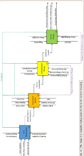
Figure 32-Decoupled Node A0 ... 49
Figure 33-Node A1 (Task Clarification Phase) ... 50
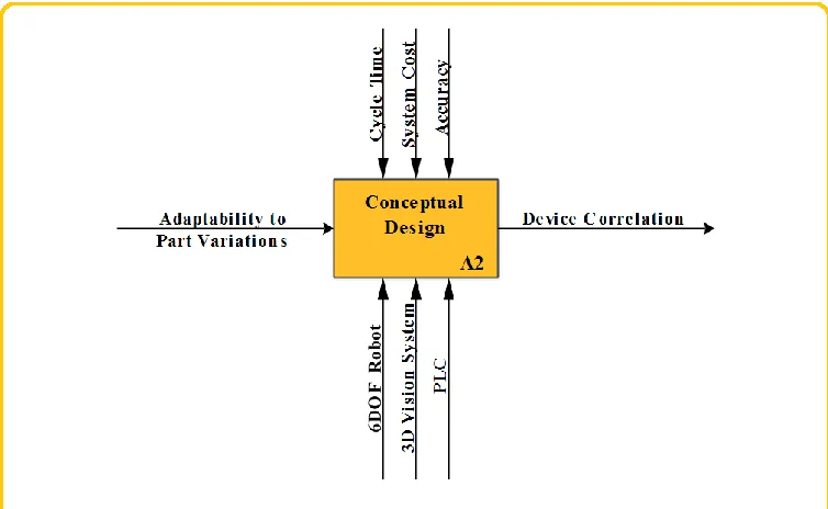
Figure 34-Node A2 (Conceptual Design Phase) ... 50
Figure 35-Node A3 (Embodiment Design Phase) ... 51
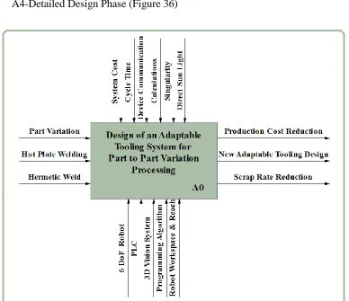
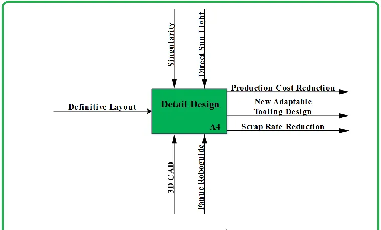
Figure 36-Node A4 (Detailed Design Phase) ... 51
Figure 37-Test Robot-Fanuc R2000 iB 165F ... 53
Figure 38-Test PLC-Siemens S7 ... 53
xi
Figure 40-Test HMI-Siemens ... 54
Figure 41-SPM Automation Prototype Cell... 55
Figure 42-Fuel Tank Section ... 55
Figure 43-3D CAD Illustration of Position Variations ... 56
Figure 44-3D Vision System Distance Setup ... 58
Figure 45-Robot EE Connector ... 59
Figure 46-Electrical Junction Box ... 59
Figure 47-Robot Configuration Program Section ... 60
Figure 48-Robot Path and Communication Protocol Program Section ... 60
Figure 49-Robot Major Axis Translations ... 61
Figure 50-Robot Minor Axis Translations ... 61
Figure 51-Robot “Master” Position and Offset Check ... 62
Figure 52-Robot Position Adjustment ... 62
Figure 53-Robot Protocol ... 63
Figure 54-Robot Protocol ... 63
Figure 55-Camera Software Screen ... 64
Figure 56-ROI Definition © 2017 IEEE ... 65
Figure 57-Blob Finder Tool © 2017 IEEE ... 66
Figure 58-Methodology for Placing "Best Fit Plane" ... 67
Figure 59-Best Fit Plane Placement on 3D Surface © 2017 IEEE ... 68
Figure 60-Compound Plane Angle Calculation ... 69
Figure 61-X and Y Minor Points Calculation © 2017 IEEE ... 70
Figure 62-X and Y Minor Plane Calculation © 2017 IEEE ... 70
Figure 63-Scratch Pad and Master Coordinate Placement ... 72
Figure 64-HMI Display... 74
Figure 65-Robotic Accuracy and Repeatability Illustration ... 78
Figure 66-PR[171] Coordinates (Master Position) ... 80
Figure 67-Register Values (Offset Values) ... 81
Figure 68-PR[172] Coordinates (Offset Position) ... 82
Figure 69-Verification Plate ... 83
Figure 70-Verification Plate CAD Model ... 83
Figure 71-3D Scan of the Verification Device ... 84
Figure 72-Verification Confirmation ... 84
Figure 73-Image Scan Repeatability Test ... 87
Figure 74-Test Video Image ... 88
Figure 75-System Architecture ... 93
Figure 76-Scan Without Direct Sun Light Exposure ... 99
Figure 77-Scan Affected by Direct Sun Light Exposure ... 99
xii
LIST OF TABLES
Table 1-Academia Research Gaps ... 21
Table 2-Patent Research Gaps ... 25
Table 3-Robot Specifications ... 53
Table 4-PLC Specifications ... 53
Table 5-3D Vision System Specifications ... 54
Table 6-HMI Specifications ... 54
Table 7-Device IP Addresses ... 57
Table 8-PR[171] Position Coordinates (Master Position) ... 80
Table 9-Register Values (Position Offset Values) From Scan Image ... 81
Table 10- PR[172] Position Coordinates (Offset Position)... 82
Table 11-System Tolerance/Repeatability ... 86
Table 12-System Comparison ... 89
xiii
NOMENCLATURE
6 DoF Six Degrees of Freedom. Describes robot freedom of movement.
5 DoF Five Degrees of Freedom. Describes robot freedom of movement.
Com Communication Values
DI [ ] Digital Input
DO [ ] Digital Output
EE End Effector Connector
EOAT End of Arm Tool
HMI Human Machine Interface
IDEF0 Icam DEFinition for Function Modeling. ICAM is an acronym for Integrated Computer
Aided Manufacturing
I/O Input and Output
ISO Isostatic
LBL Robot Label
M Measured Values
mm/sec Millimetres per second
OEE Overall Equipment Effectiveness
PLC Programmable Logic Controller
PR[ ] Position Register
R [ ] Robot Register
Ref Reference Values
RI [ ] Robot Input
RO[ ] Robot Output
ROI Region of Interest
SC3DTM Single Camera 3D Technology
TCP Tool Center Point
TCP/IP Transmission Control Protocol/Internet Protocol
TP Fanuc Programming language used by Fanuc Robotics for robot programming
VGR Vision Guided Robotics
1
CHAPTER 1:
INTRODUCTION
1.1 Conventional Plastic Welding
In order to keep manufacturing systems in line with fast-moving pace of OEM demand,
Tier 1 plastic suppliers are faced with a challenging request to keep the production lines at
such pace. Any kind of alteration in the process will create the variation in part geometry,
resulting in a need to readjust the processing units to the part (e.g. blow moulded plastic
fuel tank). Depending on the process, this task may take long periods of time as once the
processing units are adjusted, initially manufactured components are required to go through
quality control prior to the manufacturing line continuing with the production. This
provides motivation for the development of a machine system which should reduce waste,
and increase efficiency and productivity, while preserving high value human involvement
(H. A. ElMaraghy, 2009). Most critical weld are referred to as hermetic welds, which are
commonly found in all components which provide fuel transfer to the inside/outside of the
fuel tank; such as inlet check valve (ICV).
2
These welds are created by one of the most popular thermoplastic joining methods called
hot plate welding. This method works by placing two components at the hot plate surface,
whose surface is then heated by conduction to promote component melting. Upon reaching
predetermined amount of melt at the molten surfaces, the heat source (i.e. hot plate) is
removed and the two components are brought together. Two components are then held
together and allowed to solidify producing the weld. A certain amount of weld flash created
by the molten plastic is squeezed out of the joint assuring adequate fusion between the
components (Grewell & Benatar, 2003).
Processing units used for this welding operation are referred to as the Fusion Units.
Controlled by the closed loop control system, these units are equipped with multiple
sensors for position and force monitoring. They consist of different subassemblies such as
Component Gripper which is used to retain the part being welded to the fuel tank, Part Hot
Plate used to melt the component welded to the fuel tank shell, and Tank Hot Plate
assembly used to promote the melt on the fuel tank surface. Figure 2 illustrated this unit.
3
Fusion Units are normally guided to the fuel tank area by linear slide or robot, from which
point welding process takes place. Tank Hot Plate is brought into contact with the fuel tank,
at which point simultaneously Component Gripper is advanced to the Part Hot Plate,
promoting the part in the Component Gripper to melt. Once both melt pools are created,
Tank Hot Plate is retracted from the fuel tank, Part Gripper is retracted from the Part Hot
Plate, and melted part is brought into the contact with the melted surface on the fuel tank,
followed by solidification process.
The task of processing unit readjustment is typically performed by maintenance technicians
and is usually required every time a different batch of parts is introduced (i.e. WIP,
change-over, rework parts, etc.), part of the process is altered, or even air moisture content is
changed due to the outside temperature. All these factors can result in component or
component feature location to change position and/or shape.
This chapter will discuss robotic and fixed processing units commonly found in plastic fuel
tank manufacturing systems. It will also cover the need for automatic adjustment systems.
1.1.1 Welding Process Steps
It is imperative to understand the plastic welding phases/steps in order to convey the
impotence of this research. Following plastic welding phases are defined by (Grewell &
Benatar, 2003).
Matching: is the initial stage of the plastic welding process which requires increased force
applied by the hot plate (controlled by load cell) in order to conform the fuel tank surface
to the hot plate geometry. This process eliminates normally found surface deformation
4
the heating stage. Displaced material is incorporated in the flash past the hot plate
perimeter. Time for this stage is determined experimentally usually by trial and error until
the desired result is achieved.
Heating: is the second part of the heating process which starts immediately after the
matching stage without any mechanical movement of the processing unit. The force of the
hot plate during the matching phase is decreased to a minimum (controlled by load cell)
and the surface is allowed to be melted without any material displacement (energy is
transferred through conduction heat transfer). Heating time may be determined
theoretically or experimentally and checked through the microtome process (Wikipedia,
2016a) until heat affected zone of 0.4 mm is achieved.
Change-Over: is the mechanical movement of the parts at the end of the heating phase,
which occurs by moving each part out of the contact with the respective hot plate. In the
fuel tank welding, tank hot plate is removed for the fuel tanks surface, respectively
retracting the component gripper form the part hot plate. This is followed by the position
change of the tank hot plate cylinder and the part gripper cylinder, positioning the part
gripper directly over the melted fuel tank surface and bringing the melted parts together.
Change-Over time should be kept under 5 seconds for high-density polyethylene (HDPE)
welding in order to avoid surface cooling of the melted components.
Fusion: is the last stage of the process. It refers to parts being placed in contact together
under pressure and allowed to cool and solidify, completing the welding process. Joining
pressure is monitored by the load cell in order to assure that the correct amount of melt is
squeezed into the weld flash around the component. Having the pressure set too low during
5
between the components at the weld interface. Further, having the pressure set too high
will squeeze all the melt out of the joining area, creating an effect called “cold weld” (virgin
un-melted materials are below the melting point and act as a stop) resulting in a weak weld.
Figure 3-Outside and Inside Image of Component Properly Welded to Fuel Tank Body
1.2 Hard Fixed Processing Units
Dedicated production lines are commonly equipped with the fixed processing units
composed of the Fusion Unit attached to the machine frame via adjustment unit. This
allows the Fusion Unit adjustment in 3 major and 3 minor axes to the fuel tank surface,
resulting in tank hot plate being able to conform to the center of the feature and provide
parallel rectification of the hot plate to the hole weld surface. The process begins by the
fuel tank entering the station and clamping in the tank fixture. Once clamped in the tank
fixture, the processing unit is advanced usually by a linear slide, followed by the welding
of the component to the fuel tank surface which seals the hole opening. This conventional
6
the processing unit are used to assure that the contact between the processing unit and the
fuel tank is made, without monitoring the accuracy of finding the correct location and
parallelism to the weld surface. Once the operation is completed, the weld seal/quality is
checked in the helium leak station (the process performed later down the line) where the
fuel tank is tested for hermetic seal once all the components have been welded.
Figure 4-Fixed Mounted Fusion Unit Position Relative to the Fuel Tank Fixture (Courtesy SPM Automation (Canada) Inc.)
1.3 Robotic Processing Units
Robotic production lines are normally equipped with the same Fusion Unit as dedicated
equipment. This unit is used as EOAT which is attached to the robot 6th axis. These robotic
configurations are found either as stand-alone cells or as a part of the larger production line
(e.g. index table or linear transfer production line) in the manufacturing settings. In either
case, once the fuel tank is clamped in the tank fixture, the processing unit is advanced to
7
of the processing unit being mounted to the robot or the mechanical adjustment unit, the
process is still considered “blind” welding since the sensors and load cell is used to provide
the feedback that the contact is made and the weld is performed.
The advantage of having the processing unit mounted on the robot over the mechanical
adjustment unit, is in the position re-adjustment time. Recording the new robot position is
much faster and easier than mechanically trying to adjust the processing unit to the fuel
tank surface.
8
1.4 Current Industrial Practice
In order to understand why the part variation occurs in the automotive fuel tanks and the
need for this application, research needs to briefly describe the manufacturing process. As
automotive fuel tank with the typical shrink rate of 4% is used in the case study, this section
will discuss the shrink control, direction, and datum points of the fuel tank. Considering
the component length of 1.4 meters as outlined in the example below, length deviation of
5.6 cm in overall length can be expected from the blow moulding process to the final
pack-out stage when the fuel tank should stabilize to room temperature. However, since the
welding process is performed about halfway through the production, shrink rate is still very
active and part variations can be observed (comparing work in progress to already cooled
fuel tanks) during the welding stage. To overcome this issue, manufacturers design and
utilize datum geometry on the fuel tanks commonly referred to as the isostatic (ISO) locator
features. Typically, there are 2 ISO features on the fuel tank; 4-way constraining the part
location in two directions and 2-way constraining the part in one direction. Combined
together, these features control the geometry of the fuel tank during the shrink stage in the
welding process. ISO features are also used as the datum points to measure the compliance
9
Figure 6-ISO Feature Location on Fuel Tank
Figure 7-ISO Pin Assembly on Tank Fixture (Courtesy SPM Automation
(Canada) Inc.)
10
As illustrated in the figures above, fuel tank fixtures used in the welding process contain
assemblies designed as the reverse side of ISO features, called “ISO Pin” assemblies. These
assemblies are part of a typical tank fixture design in the fuel tank welding industry.
Combining ISO feature on the fuel tank with the ISO pins on the tank fixture provides
consistent fuel tank location in the tank fixture relative to datum locations. However, as the
shrink factor is still active and the fuel tank is still changing in terms of geometry, shrink
magnitude may move through the 2-way ISO towards the 4-way pin in the tank fixture as
shown in the figure below.
Figure 9-Fuel Tank fixture Cross Section (Courtesy SPM Automation (Canada) Inc.)
As mentioned earlier regarding the process stability and the fuel tank variation during the
welding process, Figure 10 below illustrates a 2-way ISO pin assembly designed to allow
11
Figure 10-2-Way ISO Pin Assembly Cross-Section (Courtesy SPM Automation (Canada) Inc.)
To conclude above-mentioned details, ISO structures drive the fuel tank manufacturers to
position all hermetic welds in close proximity to 4-way ISO feature in order to eliminate
feature location variation driven by the shrink. This in return constrains the fuel tank
geometry design and configuration of the fuel tank. Therefore, it is common to find all
hermetic welds in close proximity to the 4-way ISO feature, as locating hermetic seals in
more remote locations from the 4-way feature will result in constant equipment adjustment
and increased scrap rate.
Other factors such as manual handling of hot blow moulded fuel tank by manual
de-flashing operations and transferring the part to the next process contribute to the fuel tank
geometry variation as well; however, this will not be covered in this study as the research
12
1.5 Research Motivation
As some part to part variations are acceptable in the mass-production manufacturing
process, others may not be. Regardless of the use in dedicated or flexible manufacturing
production lines, processing units are designed to come in contact with the fuel tank surface
and weld the component. This position is adjusted by maintenance or setup technicians and
therefore it is always in fixed orientation and position relative to the fuel tank. And while
fuel tank surface might change, the processing unit will always advance towards the same
position in 3D space. Even though force sensing and monitoring is an integral part of the
closed loop controls system which monitors the welding process, the result of the welding
operation is that the components are welded to the fuel tank surface without knowing if the
correct position and/or angle to the weld location are attained. Aside from the component
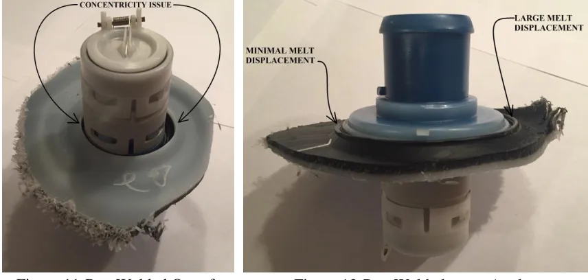
being welded out of concentricity with the feature (Figure 11), this also may cause damage
to ethylene vinyl alcohol (EVOH) layer (Figure 13), if the hot plate surface on the
processing unit is not parallel with the hole weld surface on the fuel tank. Figure 12 displays
13
Figure 11-Part Welded Out of Concentricity
Figure 12-Part Welded on an Angle
Figure 13-Fuel Tank Blow Moulding Layers
EVOH layer consists of 3% overall fuel tank wall surface and is used as a hydrocarbon
barrier to prevent volatile gasses from escaping through the fuel tank wall (SIMONA,
2010). Though it is located closer to the inside wall of the tank surface, EVOH layer
damage may become undetected during the manufacturing process if an angular mismatch
14
Figure 14-CAD Representation of Misaligned Melt Phase
Figure 14 illustrates the incorrect welding position of the component shown in Figure 12.
1.6 Objective and Problem Statement
The objective of this master thesis is the design and introduction of a new method for
adaptable tooling system which would automatically adapt to part variations, especially
noticeable in large automotive plastic fuel tanks.
By doing so, the research will be able to create a methodology for establishing a
relationship between the system components, as well as their function. Currently published
literature is unfortunately limited in terms of systematic design approach regarding robotic
15
By finding the correlation between the image captured by the 3D vision system and the 6
DoF robot in 3D space, the system would be able to reposition the EOAT to the feature of
interest in the image every time the position change would occur.
The equipment selected for this work is SICK AG IVC 3D vision system, Siemens PLC,
and Fanuc R2000-iB/165F robot equipped with an end of arm tool for plastic welding.
The significance of this design is aimed to improve OEE (Overall Equipment
Effectiveness), eliminate scrap rate, simplify equipment/machine design, minimize
maintenance personnel, and decrease the cost of manufacturing by eliminating
inconsistencies.
The intent of this work is to allow for other manufacturing applications where the part to
part variation is present, to implement the presented design where part variation or
component positioning may have an impact on the production quality.
1.7 Thesis Outline
Chapter 2 will conduct a literature survey on academia, patents, of-practice, and
state-of-the-art, as this research is directed more towards the industrial applications. Chapter 3
will review the systematic design approach in terms of methodology and IDEF0 modeling.
Chapter 4 will present a case study example which will define design details with examples.
In Chapter 5 the research will demonstrate the results and the validation of the system,
which will be followed by system benchmarking. Chapter 6 will encompass discussions,
16
CHAPTER 2:
LITERATURE REVIEW
2.1 Overview
The study of vision-guided robotic systems using different tools has been a topic of interest
in both manufacturing industry and academia. As such, this chapter will encompass
different sections relating the research to academia, patents, of-the-practice, and
state-of-the-art.
The first part of the chapter will encompass the review of academic work, followed by the
review of the existing industrial patents. The third part will cover the discussion on
state-of-the-practice technique, followed by the discussion related to the state-of-the-art in the
industry. Many journals and patents have been researched, however only the ones most
related to this research have been cited and covered in this thesis.
2.2 Academia
This section will discuss research covered by academia related to vision-guided robotic
systems.
(Šuligoj, Šekoranja, Švaco, & Jerbić, 2014) proposed object tracking with 2 robots and
stereo vision cameras. The problem was addressed by using 3 points on the part pallets
used to track the object with the vision system. The system was constructed by two cameras
mounted on the first robot, while the second robot carried the markers. Camera robot would
monitor the position of the marker robot and advise it on its position relative to the object
by calculating the position between the robot’s tool center point (TCP) relative to the part
17
transmission control protocol/internet protocol (TCP/IP). This system shows a level of
complexity as well as constraints. In order to make the system functional, markers
described in the research must be present in order for the second robot to track the object
and coordinate the position to the robot performing the operations. Without the markers,
the system would not be able to perform, making it prone to failures. Authors presented a
viable solution for robot guidance; however, the integration of the two robots in sync makes
the system very expensive and intricate due to the synchronizing process.
(Bellandi, Docchio, & Sansoni, 2013) proposed using one robot and two cameras (one in
2D and second in 3D) in order to reposition robot to the object more accurately and faster.
The camera is presented as a “stand-alone” device in the 2D, and combined with a laser
slit projector in the 3D system operating in triangulation mode, it creates a system used for
object location and fitting. Research describes the arrangement composed of both cameras
fastened to the robot end of arm tool (EOAT). This concept arrangement describes a system
where the 2D geometric template matches and classifies the 3D object in order to get a
more robust and faster processing solution by eliminating the cloud segmentation and
object classification. By excluding the point cloud, 3D data is used for calculating location
as well as the object orientation in order for the robot EOAT to be properly oriented to the
object/feature of interest. This system shows enough accuracy for pick and place
applications, however it is constrained to objects with simplified shapes such as cylinders
and flat surfaces (planes) and would have limitations in recognizing and analyzing objects
which contain 3D surfaces (object height changing in Z direction) where multiple features
18
(Martinez, Boca, Zhang, Chen, & Nidamarthi, 2015) research comprised of one robot
equipped with the stereo camera for random industrial bin picking applications. The study
describes the methodology on coordinate system synchronization between the two devices,
meaning that any scanned object would have its position directly related to the robot. Each
object is analyzed for access to picking position prior to robot advancement. Due to EOAT
size, the system was required to use 2 tool center points (TCP), and develop a procedure
for robot extraction path once the objects were grasped in order to avoid a collision.
Research demonstrates teaching methodology for using two different tool center points
(one for each part gripper on EOAT) and calibrating them together, along with other
methods such as robot extraction. System indicated some limitations regarding the part
orientation which was impacted by larger EOAT, as well as longer cycle time produced by
the algorithm used for object location and positioning.
Another bin picking application was presented by (Oh, Lee, & Lee, 2012). This research
describes the design of the system on the similar platform for pick and place application as
(Martinez et al., 2015). Published paper defines the application where one robot and two
cameras are used to locate the object. By using a larger field of view and geometric pattern
matching method with the respect to the 2D image, this concept allowed for a more robust
system which would be capable of locating components that would previously generate
faults. Designed for industrial applications, the system incorporated collision avoidance by
using the object orientation with respect to the bin orientation, increasing the system
reliability. The system did show certain sensitivity to outside elements (i.e. lighting) which
limited the system in high accuracy applications. After presenting the system at Korea
19
(Semim, Jr, Silva, Silva, & Tormena, 2012) developed another concept on using the vision
system for positioning the robot EOAT to the engine head which may vary in position and
orientation. Computed vision system program was created by using Pearson Correlation
(Yen & Johnston, 2005) to determine the object position and orientation. The correlation
of the image and the robot EOAT was created by corresponding holes on the engine head
to the tool center point on the EOAT. Change in engine head position (displacement
position) was then transferred to the robot TCP position which would then be adjusted with
the same displacement values.
Charge-coupled device (CCD) camera integrated with 5 degrees of freedom (5 DoF) robot
was explored by (Xie & Hämmerle, 2008). Research selected somewhat limited 5 axis
robot, equipped with the CCD camera on the end effector. To achieve the accuracy of the
vision system, new image processing technique was developed by using a pinhole camera.
Object recognition was performed by using 2D and 3D cameras; by taking images from
different angles in order to achieve accurate object angle position. This at the same time
eliminated the possibility of generating an inaccurate image and adjusting the EOAT
incorrectly if clustered objects are present in the work envelope. In addition to this, the
procedure used color instead of grayscale images, improving object tracking and
registration. It is imperative to acknowledge that the experiment utilized kinematics in
order to eliminate the vibrations created during the robot joint angles during the object
20
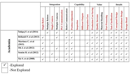
2.2.1 Academic Literature Review
Current academic publications relevant to this research were reviewed in the previous
section. The approach used by the academia illustrates different methods of adjusting the
robot end effector to part variations or differently positioned objects. The experiments
performed include a well-defined systematic approach to providing object recognition and
orientation in 3D space by using different robot arrangements in conjunction with single
or dual cameras. By using existing or developing a custom cloud platform for object pattern
matching the studies were tested for material handling (i.e. pick and place) applications.
Academic research identifies a level of complexity inadequate for manufacturing settings,
as certain industrial components (such as PLC) are not utilized, and proposed custom
programming software is often not recognized and/or approved by the industry.
Experiments displayed do not directly satisfy part processing applications (e.g. welding,
screwing, trimming, etc.) by using a single robot in conjunction with a single 3D vision
system and the PLC. However, methodologies displayed provide a good starting point that
21
Table 1-Academia Research Gaps
-Explored -Not Explored
2.3 Patents
(Richard, 2008) wrote an article on robotic guidance where he mentioned that marriage of
vision and robotics is changing the robotics nature, by going from pre-programmed
directions to the robots which are starting to “find their way” in a manufacturing
environment. This can commonly be observed at the robot conferences and/or shows,
which is usually followed by the industrial pretense. And even though most of the
manufacturers and/or integrators are very secretive regarding the methodology on the
robotic guidance, some patents may uncover details on the advances.
Patent assigned to ABB Robotics Inc.(Thorne, 1997), explains the robotic control system
for repositioning the EOAT to the new position with the assistance of video display
showing the coordinate points of the EOAT. Work points recovered from the robot
22
This allows the technician to select and designate the work points which are to be
manipulated in terms of position and/or location. Once the points are saved, the program
is then recorded to the robot controller. The patent demonstrates easier manual
manipulation of the robot adjustment with the help of the 3D screen, however, it still
requires human assistance each time robot manipulation is required.
Another ABB Robotics Inc. assigned patent (Abare et al., 2003), describes the robotic
pallet welder machine used for manufacturing plastic fuel tank and adapting to different
part variations. This configuration describes the linear transfer machine with multiple
processing stations (i.e. boring and welding). Patent defines the system which includes 3D
vision camera located on the overhead support above the fuel tank. The vision system scans
the area of interest on the fuel tank during each cycle, once the palletized fuel tank enters
the station. Once the scan is completed, the location and the planarity data are
communicated to the robot processing the part. The patent further goes on describing the
robot and machine arrangement, as well as a brief description of the sequence of operations.
However, the patent does not describe the algorithm, communication protocol or any other
detailed description regarding the robotic adaptability to part variations. In addition to this,
this machine setup with the overhead 3D vision camera (assuming the 3D vision system is
mounted on the servo linear slide), creates the constrain for the vision system scan path, as
the feature of interest on the fuel tank may not be positioned directly under the camera.
This would require various overhead support designs for different products, constraining
the production line to the product on which the overhead support is designed to, and
23
(Oxenfarth, 2007) describes a 3D vision system for position and angle readjustment of the
processing unit in fuel tank applications. The patent designates two different robot
arrangements. The first arrangement describes the relationship between the two robots, one
of which carries 3D scanner while the second robot carries the EOAT for plastic fuel tank
welding. Once the first robot would scan the area of interest, the position would be
translated to the second robot with EOAT, which would adapt to the new position. This
shows some similarity in the arrangement with (Abare et al., 2003), with the exception that
the camera is mounted to the robot instead of the overhead frame structure. (Oxenfarth,
2007) presented the second arrangement with the 3D vision camera being mounted to the
EOAT on one robot, eliminating the second robot altogether. This physical component
arrangement appears to have certain similarities to this thesis research as well as patent
applications (Novakovic & Holtkamp, 2017a), (Novakovic & Holtkamp, 2017b), and
(Novakovic & Holtkamp, 2017c). Aside from the robot arrangement, this patent does not
provide any description of the algorithm, device correlation, or communication protocol
description.
(Weber, Lane, & Novakovic, 2012a) and (Weber, Lane, & Novakovic, 2012b) is another
patent for fuel tank finishing/welding applications. The patent describes the tooling
arrangement and operation of scanning the outside surface of the fuel tank and triangulating
the position to the robot, for positioning/welding components inside the workpiece interior
(i.e. fuel tank) and the method of using the same. The patent describes 3D scanning of the
object exterior surface and triangulating the feature position back to the robot in order to
reposition the components holder to the inside of the work piece for welding. Once the
24
pump) access opening and positions the component into alignment with the inside contact
surface under the region of interest. Published material provides the information that the
3D vision camera, robot controller, and the PLC devices are used. However, the patent
publication does not go into detail describing the systematic approach, algorithm,
component correlation, or method on device communication/protocol.
2.3.1 Patents Literature Review
Patents review section seems to follow a very similar pattern in terms of patent information
availability. The majority of the systems are used for part processing without providing
enough manifestations on the systematic approach or details to understand the system
structure and methodology (Risch, 2015). This is mostly as these systems are considered
trade secrets (Canadian Intellectual Property Office, 2015) and manufacturers are wary of
releasing any information as patents do not always provide full protection. This in return
makes these systems difficult to understand or to be built by the person skilled in the art.
Although reviewed patents do not satisfy this research criterion in regards to the design
detail, the objectives specified can be used for selecting an appropriate approach for the
25
Table 2-Patent Research Gaps
-Explored -Not Explored
2.4 Industrial State of the Practice
Since the introduction of vision guided robotics (VGR), the initial systems were introduced
with 2D vision cameras. This arrangement allows for X, Y, R or X, Y, Z robotic adaptation
depending on the camera used (Fanuc Robotics America, 2012). The introduction of 2D
vision-guided robotic systems allowed for significant scrap reduction in material handling
operations depending on the application. And even though 3D vision guided robotics have
been introduced to the industry, many applications still remain utilized by 2D systems,
forcing manufacturers to keep advancement on these systems. Applications using
randomly placed objects on the same plane where the object tilt is not present are an ideal
application for these systems (Anandan, 2014). These systems are fully pre-programmed
with the set of tools utilized for the application (e.g. parameters, conditions, etc.). The user
interface allows for easy setup and the PC-based programming tools provide a platform for
easy integration (ABB, 2013). However, once the object tilt angles do become present, 3D
26
2.5 Industrial State of the Art
Part variety and product demand change drive the need for flexible manufacturing systems.
Constant tooling change-over and the introduction of new production components requires
perpetual tooling/machine adjustment until the production is stable. In order to solve this
issue, many equipment manufacturers turn to readily available industrial solutions. Robotic
manufacturers such as Fanuc and ABB were some of the first in the industry to introduce
vision-guided robotic systems.
Fanuc iRVision consists of several platforms (Fanuc Robotics America, 2016):
2D Vision Guidance allows the robot to accurately position the EOAT to the part
location in X, Y and R (rotation) position.
3DL Sensor provides the robot with the ability to position the EOAT in X,Y,Z
location as well as the angle and rotation (W,P,R).
Visual Line Tracking system is based on the 2D vision camera platform. The
system provides the ability to the robot to pick and place the components to/from a
moving conveyor by monitoring the encoder sensor which provides the conveyor
speed and the position of the object on it.
Vision Guided Depalletizing is another form of a system built on the 2D platform.
In addition to X,Y,R direction corrections and calculations, the system will also
calculate the Z height and reposition the tool center point accordingly.
Unlike Fanuc, ABB uses third part vision systems in order to provide their robots with the
vision guidance (COGNEX, 2017). Companies like Cognex and Braintech provide this
27
different uses; such as bin picking and processing applications. This approach provides
ABB with similar capabilities as Fanuc (ABB, 2008).
2D Vision Guidance allowing robot to accurately position the EOAT to the part
location in X, Y and R (rotation) position.
Single camera information in 4 degrees of freedom (X,Y,Z,R)
Single camera 3D technology for full 6 degrees of freedom adjustment
(X,Y,Z,W,P,R)
Surround 3D imaging combining information from multiple cameras viewing parts
from different angles
2.6 Summary
Literature review presented in this chapter summarizes academic, patents,
state-of-the-practice and state-of-the-art solutions regarding vision-guided robotic applications for the
part to part variation handling. As creative and efficient academic solutions may be, they
do not present a feasible solution to the industrial requirements, mostly due to the level of
complexity and lack of industrial devices use. Patents, on the other hand, do not disclose
enough information on the system design or detail to understand the structure or the
function. State-of-the-practice and state-of-the-art provide already well-developed
solutions but do not disclose any information in regards to system design. Rather, they
provide an out-of-the-box solution for the integrators. Therefore, the research and results
28
CHAPTER 3:
DESIGN OF AN ADAPTABLE TOOLING
SYSTEM FOR PART TO PART VARIATION PROCESSING
3.1 Systematic Design Process
The primary objective of this research thesis is to design a system that would automatically
adapt to part variations commonly found in the plastic manufacturing industry. Planning a
system design where different components are assembled in order to provide this objective
brings uncertainties which need to be addressed prior to components integration. In order
to achieve this design, extensively used IDEF0 as well as systematic design approach by
(Pahl, Beitz, Feldhusen, & Grote, 2007) was chosen in order to select, configure, and
integrate components into the system, by observing and eliminating the constrains each
component might carry.
29
3.1.1 Task Clarification
The fundamental problem in many blow moulded components processing is the part
variation. This variation leads to major automotive recalls which more often than not,
create large volumes of fuel tanks which needed replacing in the past (Grande, 2011),
(ARFC, 2002) and are still occurring (Mazda, 2016b), (Honda, 2016), (Mazda, 2016a).
Part to part variations typically found within mass produced plastics parts requires periodic
machine adjustment by maintenance technicians. This in return generates production
downtime, extra production cost, increases scrap rate and lowers overall equipment
effectiveness (OEE).
In order to eliminate this issue, adaptable tooling system is required so the feature on the
fuel tank and component being welded can be matched correctly. Readily available
industrial components such as robots, PLCs, cameras, etc., will only be used for the system
design.
Process cycle time should be lower than compared to current production as the ideal
condition would always be achieved, and the need for the matching time to conform the
fuel tank surface to the hot plate is decreased.
The system should allow for easy integration into existing robotic production without
major equipment changes. The addition of the system components (i.e. camera) to the
current production system should be performed with ease, assuming that the current
30
Once integrated, the robot should automatically adjust the EOAT to the new position on
the fuel tank where the feature of interest is deviated. Thus, resulting in adaptability to part
variations.
3.1.2 Conceptual Design
In order for the system to reposition the processing unit to the new feature location, it is
essential that the system is capable of adjusting in X, Y, Z, W, P, R directions. Thus, 6
degrees of freedom (6 DoF) robot will be used in order to provide the flexibility in position
adjustment and orientation. In addition to the robot, other components listed below will
need to be used in order to administer the position change.
3D vision system will be used for topology generation.
PLC will be used to provide communication between the network devices and to
perform process making decisions.
Processing unit will be used as robot EOAT for fuel tank welding.
Robot required for the application should have the ability to adjust in 6 degrees of freedom;
therefore, an articulated 6 DoF robot is required. For this application, an existing Fanuc
R2000-iB/165F robot will be utilized. Since Fanuc robots are most commonly found in the
worldwide manufacturing settings (Christensen, 2016), Fanuc TP robot programming
language is well developed for most operations regarding the robot movement and position.
Having the camera mounted as part of the EOAT, two user tools will be assigned to the
31
can provide direction and velocity, producing an accurate and repeatable camera scan start
location, which will be used for analyzing the object topology. This procedure is achieved
by moving the robot over top of the object and scanning the surface on the initial component.
Once this is performed, the camera will record the feature position (i.e. hole) in terms of X,
Y, Z, W, P, R location, while simultaneously robot user tool position is recorded to the same
physical feature of interest (i.e. fuel tank hole) location. This procedure creates a correlation
between the feature of interest on the camera image and the robot EOAT position register
(PR). This position will be assigned as the “master” point from which all subsequent feature
locations will be measured. Once position difference on the next component scan is
calculated by the camera, the variation in position will be sent to the PLC where it will be
checked and then transferred to the robot. The robot will initially move EOAT to the
“master” position, and then perform the difference in location regarding X, Y, Z, followed
by W, P, R directions. Once process (i.e. welding) is completed, the subsequent component
can be processed.
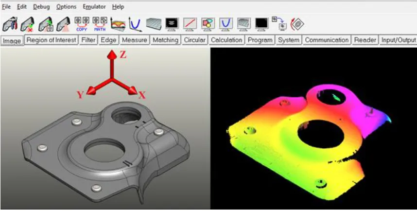
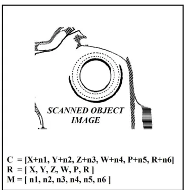
32 3D vision system will utilize manufacturer’s software and tools in order to find features in
3D space (SICK, 2013). Once feature location and position in 3D space is recorded, it is
referenced to the image upper left-hand corner (origin point). It is essential to mention that
this image corner is located on the image start scan line. Thus, moving the scan start
location without repositioning the object will change the feature location on the image.
Therefore, it is critical to assure that the image scan location is repeatable and accurate.
Figure 17-3D CAD and 3D Scanned Image
Once the first image (“master”) is scanned, the position of the feature will be marked as
[0,0,0,0,0,0] (meaning that the “position offsets” are not present), from which all other
position will be measured. Once calculated, all changes in position will be sent to the PLC.
Siemens Step 7 PLC system will utilize a Ladder logic programming, typically found in the
manufacturing plants throughout North America (Smith, 2003). This type of programming
33
Part of a PLC referred to as Function Block Diagrams (FBD) will be utilized for describing
the function between the input and output variables.
Figure 18-PLC Program Example
However, due to PLC inability to send or receive decimal values to and from other network
devices, position locations will be required to be converted into integers prior to any
communication.
EOAT will utilize a standard processing unit (i.e. Fusion Unit). Unit consist of the following
assemblies:
Tank Hot Plate: used for fuel tank melting
Part Hot Plate: used for melting the component being attached to the fuel tank
34
Figure 19-Fusion Unit Design (Courtesy SPM Automation (Canada) Inc.)
Robot TCP is recorded at the extension of “Component Gripper” cylinder 20 mm prior to
the end of cylinder stroke (380 mm from the position shown in Figure 19).
The conceptual sequence of operations is outlined in Figure 20 below.
35
The scope of each component is outlined in Figure 21 below.
Figure 21-Component Scope © 2017 IEEE
Estimated cost of $40,000 is used as a benchmark, considering the cost of the 3D vision
system purchase ($15,000) along with the cost of programming and integration to the
existing robotic cell.
In addition to the cost of the system integration, tolerance needs to be considered. At this
point in the conceptual design stage, repeatability of the robot needs to be added to the
accuracy of the vision system. Fanuc Robotics specifies positional repeatability of ±0.2
mm (Fanuc Robotics America, 2009). However, repeatability of ±0.1 mm is possible by
using special software upgrade. SICK AG does not provide the tolerance specifications in
regards to the camera but rather uses an approach of applying various filter tools to enhance
the image and decrease the tolerance. By analyzing the components in order to determine
the possible system tolerance, pixel sizes in terms of 0.25 mm x 0.25 mm have been
36
may be positioned close to the corner between 4 pixels, and the system automatically
applying it to one of the four quadrants, the following figure illustrates this accuracy.
Figure 22-Worst Case Object Positioning by SICK AG Vision System
Considering robot repeatability of ±0.2 mm, an assumption can be made that the next scan
start position may vary by this tolerance, thus causing the scanned object in the image to
look as it has moved. Figure 22 illustrates a theoretical object centroid position in proximity
of 4 quadrants, which would automatically fall within the one it is located in. However,
due to robot repeatability, this centroid position may move to a different quadrant, thus
generating the camera repeatability of ±0.175 mm. In order to calculate the system
tolerance, both components (i.e. camera and robot) need to be added together. By doing so,
37
tolerance for adjusting the EOAT to the fuel tank, and fuel tank feature which can vary
±25.0 mm, this tolerance of ±0.375 mm provides satisfactory tolerance limit in order to
pursue the research. More details on robot accuracy and repeatability are covered in section
5.1.
PLC tolerance is not included in this calculation as this device transfers the same values
from the vision system to the robot; therefore, it is assumed that no error is created during
this information transfer.
The conceptual design stage is concluded with the use of 6 DoF robot, 3D vision system,
PLC, the processing unit, and creating the correlation between these devices. Combining
the components together will provide the system structure. This arrangement will provide
flexibility for position adjustment, allow for information exchange, and the ability to
process the parts in a production environment.
3.1.3 Embodiment Design
Embodiment design phase represents a working structure of the project, which will develop
the construction structure of each component and their purpose.
3.1.3.1 Camera Embodiment Design
Having the camera as part of the EOAT, accurate robot speed is calculated by using
38
𝑁𝑜. 𝑜𝑓 𝑂𝑏𝑗𝑒𝑐𝑡𝑠 𝑆𝑐𝑎𝑛𝑛𝑒𝑑/𝑠𝑒𝑐 = 𝑅𝑜𝑏𝑜𝑡 𝑆𝑝𝑒𝑒𝑑
Image Length
(1)
𝑁𝑜. 𝑜𝑓 𝑃𝑟𝑜𝑓𝑖𝑙𝑒𝑠 𝑡𝑜 𝐶𝑎𝑝𝑡𝑢𝑟𝑒 𝑎𝑛 𝑂𝑏𝑗𝑒𝑐𝑡 = 𝑃𝑟𝑜𝑓𝑖𝑙𝑒 𝑅𝑎𝑡𝑒
𝑁𝑜. 𝑜𝑓 𝑂𝑏𝑗𝑒𝑐𝑡𝑠 𝑆𝑐𝑎𝑛𝑛𝑒𝑑/𝑠𝑒𝑐
(2)
𝑃𝑟𝑜𝑓𝑖𝑙𝑒 𝐷𝑖𝑠𝑡𝑎𝑛𝑐𝑒 = 𝐼𝑚𝑎𝑔𝑒 𝐿𝑒𝑛𝑔𝑡ℎ
𝑁𝑜. 𝑜𝑓 𝑃𝑟𝑜𝑓𝑖𝑙𝑒𝑠 𝑡𝑜 𝐶𝑎𝑝𝑡𝑢𝑟𝑒 𝑎𝑛 𝑂𝑏𝑗𝑒𝑐𝑡
(3)
Signal to activate the camera scan is sent through the End Effector (EE) connector on
robot’s axis#2 once the position is reached. During this motion, camera velocity is attained,
as constant scan speed is required to provide an accurate image. Activating the camera scan
during acceleration or deceleration of the robot will create “stretched” or “compressed”
image, providing incorrect feature position values during the calculations.
39
Figure 24-3D Vision Scan Generation (Adopted from SICK, 2013)
During the image scan, PLC byte is sent to the camera. This byte identifies the program
step to be executed. Depending on the program structure, a byte may identify the program
step or action. As the topology is generated, programming tools are used to identify the
area of the image to be analyzed.
By using SICK IVC-3D software, an array of the tools is presented for object evaluation
as shown in Figure 25.
Figure 25-IVC Studio Tools
40 Blob Finder Tool: Used for feature analyzing once the feature is identified by the Region
of Interest (ROI) step. This step also provides the X, Y centroid location as well as the
feature size. It can also be used to provides the limit values used to set the restrictions in
part variation size (i.e. hole diameter).
Fit Surface Tool: Used to define a plane which can be used for attaining the Z location of
the feature as well as minor plane angles.
At this point, the system is able to determine X,Y,Z points and minor angles of the feature.
Once computed, the values can be converted to integers and sent to the PLC.
3.1.3.2 PLC Embodiment Design
In addition to the position integer values, different information is also transferred to the
PLC in order to assure that the scan data is correct. Values defining new image scan, fault
code, program step, offset limits, etc. are presented and then analyzed by the PLC. If the
values received are within specified limits set in the program, the data is then transmitted
to the robot and the process is allowed to continue.
3.1.3.3 Robot Embodiment Design
Once the image is recorded, the topology is analyzed by the camera and the feature
coordinates are sent to the PLC. During the new position calculation by the camera, robot
41
offset position will be determined by the information sent by the PLC. This information is
stored in the robot registers and calculated based on the information received by group
input/outputs. Initially received and stored as integers, the information is converted into
decimal values prior to adjusting to the new position.
Robot Group Inputs (GI) are organized as per below:
GI[n]=Integer for X before decimal place (4)
GI[n+1]=Integer for X after decimal place (5)
………
Robot Registers are normally used to store numbers which can be used for arithmetic
operations, cycle counts, track part counts, etc. (Fanuc Robotics America, 2003). Thus,
these registers will be used to store the values from the PLC, once converted into decimal
values per guideline below.
R[n] (X linear offset value) (6)
R[n+1] (Y linear offset value) (7)
………
Methodology and the equations of converting GI [n] and GI [n+1] as X position decimal
42
Extracting integers into a value before decimal place:
R[n]=GI[n]-128 (8)
Extracting integers into value after decimal place:
R[X:SCRATCH PAD]=GI[n+1]-128 (9)
R[X:SCRATCH PAD]=R[X:SCRATCH PAD]/100 (10)
Adding value before and after decimal together:
R[n]=R[n] + R[X:SCRATCH PAD] (11)
Once the information is extracted, the values are stored in the robot registers.
Position registers (PR) are used to store the positional information (X,Y,Z,W,P,R
configuration). Fanuc robotics provide up to 200 position registers in the controller (Fanuc
Robotics America, 2003), which are identified by the numbers. Therefore, “master”
position PR[X] is used by the case study as the position correlated to the feature center at
the master location from which all other offsets will take place. Two more position registers
are used for major and minor axis offsets. New position register for all major axis offsets
43
Initially, all offsets will need to take place in the world followed by the angular adjustments:
PR[X+1, 1]=PR[X,1] + R[n] (12)
PR[X+1, 2]=PR[X,2] + R[n+1] (13)
PR[X+1, 3]=PR[X,3] + R[n+2] (14)
PR[X+1,4]=PR[X,4] (15)
PR[X+1,5]=PR[X,5] (16)
PR[X+1,6]=PR[X,6] (17)
This is followed by the angular adjustment:
PR[X+2,4:SCAN TOOL ANG]=R[x+3] (18)
PR[X+2,5:SCAN TOOL ANG]=R[n+4] (19)
PR[X+2,6:SCAN TOOL ANG]=R[n+5] (20)
In this stage of the systematic design, the design of each component is created in
accordance with technical principles. By completing the embodiment design stage, a