University of Windsor University of Windsor
Scholarship at UWindsor
Scholarship at UWindsor
Electronic Theses and Dissertations Theses, Dissertations, and Major Papers
2018
Machine Scheduling for Multitask Machining
Machine Scheduling for Multitask Machining
Saleh YavariUniversity of Windsor
Follow this and additional works at: https://scholar.uwindsor.ca/etd
Recommended Citation Recommended Citation
Yavari, Saleh, "Machine Scheduling for Multitask Machining" (2018). Electronic Theses and Dissertations. 7409.
https://scholar.uwindsor.ca/etd/7409
This online database contains the full-text of PhD dissertations and Masters’ theses of University of Windsor students from 1954 forward. These documents are made available for personal study and research purposes only, in accordance with the Canadian Copyright Act and the Creative Commons license—CC BY-NC-ND (Attribution, Non-Commercial, No Derivative Works). Under this license, works must always be attributed to the copyright holder (original author), cannot be used for any commercial purposes, and may not be altered. Any other use would require the permission of the copyright holder. Students may inquire about withdrawing their dissertation and/or thesis from this database. For additional inquiries, please contact the repository administrator via email
Machine Scheduling for Multitask Machining
By
Saleh Yavari
A Thesis
Submitted to the Faculty of Graduate Studies through the Industrial Engineering Graduate Program
in Partial Fulfillment of the Requirements for the Degree of Master of Applied Science
at the University of Windsor
Windsor, Ontario, Canada
2017
Machine Scheduling for Multitask Machining
by
Saleh Yavari
APPROVED BY:
______________________________________________ N.Zamani
Department of Mechanical, Automotive and Materials Engineering
______________________________________________ J.Urbanic
Department of Mechanical, Automotive and Materials Engineering
______________________________________________ A.Azab, Co-Advisor
Department of Mechanical, Automotive and Materials Engineering
______________________________________________ F.Baki, Co-Advisor
Odette School of Business
iii
DECLARATION OF ORIGINALITY
I hereby certify that I am the sole author of this thesis and that no part of this
thesis has been published or submitted for publication.
I certify that, to the best of my knowledge, my thesis does not infringe upon
anyone’s copyright nor violate any proprietary rights and that any ideas, techniques,
quotations, or any other material from the work of other people included in my
thesis, published or otherwise, are fully acknowledged in accordance with the
standard referencing practices. Furthermore, to the extent that I have included
copyrighted material that surpasses the bounds of fair dealing within the meaning of
the Canada Copyright Act, I certify that I have obtained a written permission from
the copyright owner(s) to include such material(s) in my thesis and have included
copies of such copyright clearances to my appendix.
I declare that this is a true copy of my thesis, including any final revisions,
as approved by my thesis committee and the Graduate Studies office, and that this
thesis has not been submitted for a higher degree to any other University or
iv
ABSTRACT
Multitasking is an important part of today’s manufacturing plants. Multitask machine
tools are capable of processing multiple operations at the same time by applying a
different set of part and tool holding devices. Mill-turns are multitasking machines
with the ability to perform a variety of operations with considerable accuracy and
agility. One critical factor in simultaneous machining is to create a schedule for
different operations to be completed in minimum make-span. A Mixed Integer Linear
Programming (MILP) model is developed to address the machine scheduling
problem. The adopted assumptions are more realistic when compared with the
previous models. The model allows for processing multiple operations
simultaneously on a single part; parts are being processed on the same setup and
multiple turrets can process a single operation of a single job simultaneously
performing multiple depths of cut. A Simulated Annealing algorithm with a novel
initial solution and assignment approach is developed to solve large instances of the
problem. Test cases are presented to assess the proposed model and metaheuristic
algorithm.
Keywords: Parallel Machining, Multitasking, Mill-turn, Mixed Integer Linear
v
DEDICATION
Dedicated to
vi
ACKNOWLEDGEMENTS
Firstly, I would like to express my special thanks to my supervisors, Dr. Ahmed
Azab and Dr. Fazle Baki for all their help and supports through the completion of
my program. Their guidance and mentorship was the most valuable asset during my
studies. I would also like to thank my committee members Dr.Nader Zamani and
Dr.Jill Urbanic for their valuable and positive feedbacks and helpful comments.
I would like to thank Mr. Bob Hedrick for his useful comments and information, and
vii
TABLE OF CONTENTS
DECLARATION OF ORIGINALITY ... iii
ABSTRACT ... iv
DEDICATION ... v
ACKNOWLEDGEMENTS ... vi
LIST OF TABLES ... x
LIST OF FIGURES ... xii
LIST OF APPENDICES ... xiv
LIST OF ABBREVIATIONS/SYMBOLS ... xv
CHAPTER 1: INTRODUCTION ... 1
1.1 Multitasking in metal cutting ... 1
1.2 Problem definition ... 2
1.2.1 Machining Unit (MU) ... 2
1.2.2 Part Machining Location (PML) ... 3
1.3 Multitasking on mill-turns and its difference with transfer machines ... 4
1.4 Structure and functionality of mill-turns ... 6
1.5 Multi-axis machine tool features and specialties ... 6
1.5.1 Definition and applications ... 6
1.5.2 Live tooling ... 8
1.5.3 Pinch turning ... 8
1.5.4 Operation mode ... 9
1.5.5 Hard turning ... 11
1.6 Process planning for parallel machines ... 12
1.7 Significance and research motivation ... 13
1.8 Research outline ... 14
CHAPTER 2: LITERATURE REVIEW ... 15
viii
2.2 Literature review ... 15
2.3 Gap analysis ... 18
2.4 Research contributions ... 22
2.5 Solution approaches compare to the literature ... 23
CHAPTER 3: METHODOLOGY ... 24
3.1 Model ... 24
3.1.1 Assumptions ... 25
3.1.2 Nomenclature ... 26
3.1.3 Decision variables ... 27
3.1.4 Objective function and constraints ... 28
3.2 Explanation ... 34
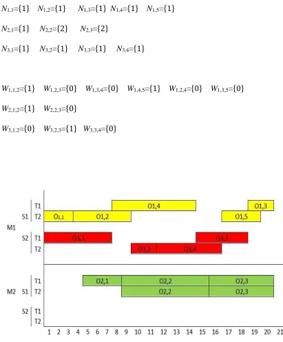
3.3 Demonstrative example ... 35
CHAPTER 4: METAHEURISTIC ALGORITHM ... 38
4.1 Simulated Annealing ... 38
4.1.1 An outlook of SA ... 38
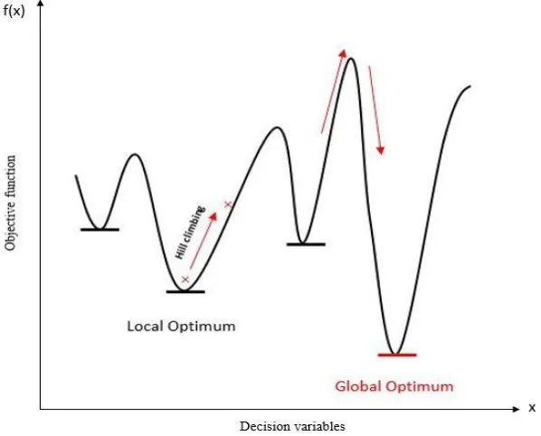
4.1.2 Advantages of hill climbing over greedy algorithms ... 38
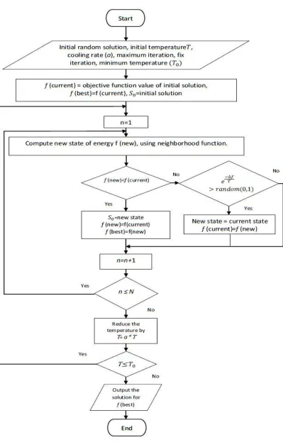
4.1.3 The mechanism of Simulated Annealing ... 39
4.2 Simulated annealing for multitasking scheduling ... 42
4.2.1 Initialization ... 42
4.2.2 Neighborhood search ... 45
4.2.3 Description of the assignment mechanism ... 45
4.2.3.1 Precedence check ... 45
4.2.3.2 Assignment of machines and spindles to operations ... 48
4.2.3.3 Assignment of turrets to operations ... 53
CHAPTER 5: TEST CASES ... 65
5.1 Experimental data ... 65
5.2 Assessment of the mathematical model ... 65
5.3 Assessment of the Simulated Annealing ... 66
5.3.1 Data analysis ... 66
5.3.2 Simulated Annealing test case1 ... 67
ix
5.3.4 Simulated Annealing test case 3 ... 69
5.3.5 Simulated Annealing test case 4 ... 70
5.3.6 Simulated Annealing test case 5 ... 71
5.3.7 Simulated Annealing test case 6 ... 72
5.3.8 Simulated Annealing test case 7 ... 73
5.3.9 Simulated Annealing test case 8 ... 74
5.4 Parameter tuning and sensitivity analysis ... 75
5.5 Evaluation of the results ... 77
CHAPTER 6: CONCLUSION AND FUTURE WORK ... 79
6.1 Conclusion ... 79
6.2 Future work ... 80
REFERENCES/BIBLIOGRAPHY... 81
APPENDICES ... 87
x
LIST OF TABLES
Table 1: Synthesis Matrix ... 19
Table 2: Processing times for the demonstrative example... 36
Table 3: Size complexity for the proposed model ... 65
Table 4: Model parameters, test case 1 ... 67
Table 5: SA parameters, test case 1 ... 67
Table 6: Computational results for test case 1 ... 67
Table 7: Model parameters, test case 2 ... 68
Table 8: SA parameters, test case 2 ... 68
Table 9: Computational results for test case 2 ... 68
Table 10: Model parameters, test case 3 ... 69
Table 11: SA parameters, test case 3 ... 69
Table 12: Computational results for test case 3 ... 69
Table 13: Model parameters, test case 4 ... 70
Table 14: SA parameters, test case 4 ... 70
Table 15: Computational results for test case 4 ... 70
Table 16: Model parameters, test case 5 ... 71
Table 17: SA parameters, test case 5 ... 71
Table 18: Computational results for test case 5 ... 71
Table 19: Model parameters, test case 6 ... 72
Table 20: SA parameters, test case 6 ... 72
Table 21: Computational results for test case 6 ... 72
Table 22: Model parameters, test case 7 ... 73
Table 23: SA parameters, test case 7 ... 73
Table 24: Computational results for test case 7 ... 73
Table 25: Model parameters, test case 8 ... 74
Table 26: SA parameters, test case 8 ... 74
Table 27: Computational results for test case 8 ... 74
xi
xii
LIST OF FIGURES
Figure 1: Work-piece held by a spindle and processed by a cutting tool mounted on
a turret ... 4
Figure 2: A dual-spindle dual-turret mill-turn ... 7
Figure 3: Application of pinch turning on a work-piece ... 9
Figure 4: Application of turn-milling on a single work-piece ... 10
Figure 5: A sample part with milling and turning features ... 11
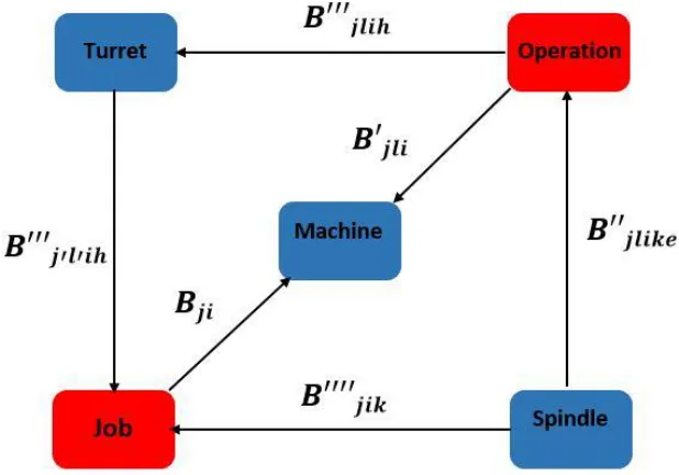
Figure 6: Relations between parameters and components of the system ... 34
Figure 7: Resultant schedule for the example ... 37
Figure 8: Hill climbing concept applied in SA ... 39
Figure 9: Simulated Annealing flowchart ... 41
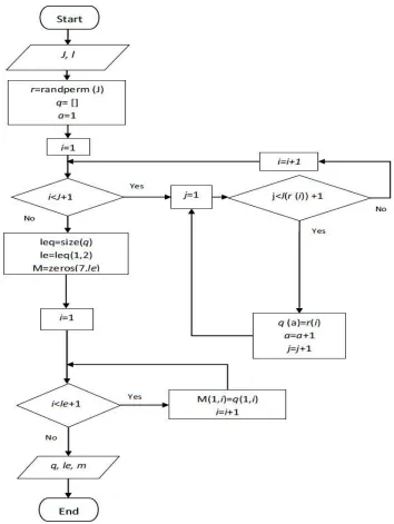
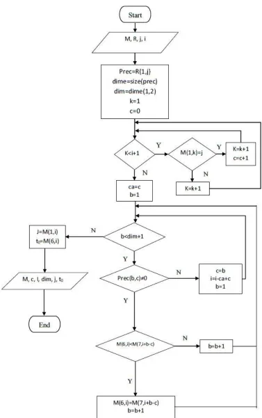
Figure 10: The initialization algorithm flowchart for multitasking scheduling ... 43
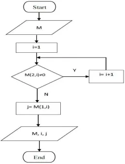
Figure 11: Machining order in the matrix M ... 44
Figure 12: Identification of jobs based on their sequence in the initial solution .... 44
Figure 13: The procedure for checking the precedence relations ... 47
Figure 14: The procedure for checking the previous assignment of any operation of a job ... 48
Figure 15: Flowchart for the first time assignment of a machine and spindle to an operation ... 51
Figure 16: Flowchart for the second time assignment of a machine and spindle to an operation ... 52
Figure 17: Flowchart for the assignment of turrets to an operation if two turrets are needed ... 54
Figure 18: Flowchart for the assignment of turrets to an operation if one turret is needed and only the first turret is available ... 56
Figure 19: Flowchart for the assignment of turrets to an operation if one turret is needed and only the second turret is available ... 58
Figure 20: Flowchart for the assignment of turrets to an operation if one turret is needed and both turrets are available (testing the first turret) ... 60
xiii
Figure 22: Flowchart for comparison between turrets to find the earliest
completion time ... 63
Figure 23: Variation of RPD for different test cases with change in the outer loop iteration ... 76
xiv
LIST OF APPENDICES
Appendix 1: FICO Xpress codes for the proposed mathematical model... 87
xv
LIST OF ABBREVIATIONS/SYMBOLS
MILP Mixed Integer Linear Programming
MU Machining Unit
PML Part Machining Location
NC Numerical Control
CAPP Computer Aided Process Planning
PMPS Parallel Machine Planning System
CAD Computer Aided Design
CAM Computer Aided Manufacturing
GA Genetic Algorithm
1
CHAPTER 1: INTRODUCTION
1.1 Multitasking in metal cutting
Mill-turn machines are machine tools with considerable abilities to machine
different work-pieces simultaneously. Although the tendency to benefit from multitasking
and parallel machine tools is increasing considerably in the industry, there has not been
enough attention in the literature to the topic. Yip-Hoi and Dutta [1] provided a genetic
algorithm for process planning operations on mill-turns. Norman & Bean [2] and Chiu et
al.[3] modeled a small scale scheduling problem on parallel machine tools. In this thesis,
multitask machining, parallel machining, simultaneous machining, or simply mill-turns are
all used interchangeably.
Mill-turns are those machine tools that resemble lathes in structure and kinematics
using spindles as work-piece holding devices, yet they carry live milling tools in their
multiple turrets [4]. Mill-turns are one step ahead of traditional lathes and vertical mills in
terms of agility and accuracy. These powerful machine tools offer some valuable features
such as simultaneous machining of a single operation of a part with multiple turrets, which
distinguishes them from other machines. Multitasking enables turning, milling, facing and
drilling operations to be done on a single setup with minimum processing times [5-7]. In
metal cutting, the final quality of products and the amount of time it takes to machine them
are critical. A mill-turn machine can process parts, which might need three to four different
machine tools to be turned into a finished product. Therefore, mill-turns offer a set of
valuable features that make them a suitable choice for metal cutting and manufacturing
industries.
2
1.2 Problem definition
Mill-turns (parallel machines) are a class of machine tools, which have gained a lot
of interest in recent years in the industry. Traditionally, CNC lathes were developed to deal
with turning tasks and machining centers equipped with rotary cutting tools were designed
to handle milling and drilling type of operations. With the application of multi-functional
machine tools, not only it is possible to continuously process a single job by more than one
cutting tool, it is also possible to machine more than one job at a time using multiple work
holding and cutting tools simultaneously [7].
Mill-turns have different configurations with a variety of applications. If a process
plan or a schedule is about to be created for a mill-turn, the configuration and category of
the machine tool considered needs to be specified. With due attention to the capacity of
these machine tools to agilely machine parts in a fast-paced environment, creating a
schedule and sequence plan to fully present these capabilities is critical. Cycle time is a
key factor in manufacturing facilities when satisfying a variety of demands with predefined
quality standards in a minimum amount of time. It is crucial to benefit the most from the
available production time and resources.
A feasible schedule plan is capable of reducing downtimes and will provide a
procedure to complete the machining processes in an optimum amount of time. The
following concepts are key to the understanding of multitask machining: Machining Unit
(MU) and Part Machining Location (PML) [8].
1.2.1 Machining Unit (MU)
Machining unit is used to hold different cutting tools on a parallel machine tool. In
mill-turns, turrets are applied as machining tools [9, 10]. The turret itself is equipped with
multiple cutting tools that can be mounted automatically for different machining purposes
[10]. There could be two or more turrets present, depending on the configuration of the
mill-turn machine.
The capacity of turrets in terms of holding cutting tools is also different from one
3
mounted on a mill-turn have limitations in terms of the rotational axis. Depending on the
configuration of the machine tool, different machines have different rotational capacities.
Machining units, which are capable to move along multiple axes have more flexibility in
terms of performing operations on work-pieces [11, 12]. Machining units are usually
located above and under the spindle. They can move along different axes. Upper turrets are
commonly capable of moving along X, Y and Z axis, lower turrets though, usually have
movements along X and Z axis. There are some configurations, which their upper turret
have the capacity of B-axis rotation. Application of B-axis is a great feature when
machining the most complicated parts that need a versatile tool orientation for the metal
cutting processes [13-15]. In order to avoid overheating of cutting tools mounted on a
turret, multitask machines are equipped with a coolant system, which is offered in different
ways. The coolant system could be applied through the coolant fluid, it can also be through
circulation of coolant inside the spindle or air blown system through nozzles directed
towards the cutting tool and the work-piece [16]. Application of the coolant depends on
the part being processed, the material used and the machine tool applied.
1.2.2 Part Machining Location (PML)
Part machining location is a location on a mill-turn machine that holds the part for
metal cutting purposes. A spindle or a chuck are common machining locations on a
multitask machine [10]. Spindles have the duty to rotate the work-piece and provide
enough energy for the metal cutting processes [17-19]. The common configurations of
mill-turns have usually two spindles applied, main spindle and a sub spindle [3]. These spindles
have access to each other so that if a specific part needs a certain type of machining process,
it could be easily moved from one spindle to another [20]. Another application of applying
the second spindle in parallel machining is using them as a tailstock. There are some parts,
which are longer to be held by a single spindle and need a second spindle to act as a tailstock
and support them while they are being machined. In some certain occasions, along with the
application of tailstock, an extra support called steady rest is used to provide further
supports while the part is being machined [21].
Spindles have different capacities in terms of loading parts. Depending on the need
4
power. Spindles of a mill-turn are fed through automatic bar feeders, which are one of the
core components of a mill-turn in terms of accelerating the process of turning raw materials
into the finished parts. Spindles and work holding supports are adjusted automatically and
without the operator's interference. The movements of spindles and turrets are programmed
through Computer Aided Manufacturing (CAM) software packages, which enable users to
simulate the metal cutting procedure and therefore, eliminate the potential errors associated
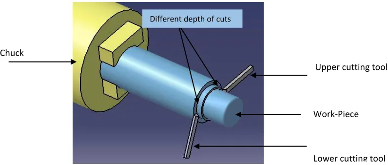
with the machining processes [22]. Figure 1 shows a sample part, which is being machined
by one of the cutting tools mounted on a turret.
Figure 1: Work-piece held by a spindle and processed by a cutting tool mounted on a turret
1.3 Multitasking on mill-turns and its difference with transfer machines
Multitasking on mill-turns is consist of three individual concepts. The first concept
is related to simultaneous machining of different parts or work-pieces on different spindles
of multitasking machine tool. This feature enables the machine tool to hold more than one
work-piece at a time and therefore, it can handle more than one machining process in a
specific time slot. The machining procedure of these work-pieces could be totally different
from each other. They could have a different schedule plan and yet be machined at the
same time without any conflict or delays in their machining processes. The second concept
is related to the simultaneous processing of different operations of a work-piece. This
feature enables the machine tool to use its multiple machining units (turrets) to machine
Turret
Spindle Work-piece
5
the part and hence reduce the total time it takes to process it. Simultaneous machining of
different operations of a part need some conditions to be met, these conditions along with
their impact on the final schedule plan are discussed in detail in the remaining sections of
this chapter. The third concept related to multitasking on mill-turns is the application of
multiple machining units to process a single operation of a part. This important feature is
also integrated into the structure of multitasking machine tools to accelerate the machining
process and deliver high-quality parts in the shortest amount of time.
Transfer machines have some common features with mill-turns and there are some
differences in terms of kinematic and structure. Both mill-turns and transfer machines have
the capacity to process different parts at the same time but there are some differences that
need to be discussed. Transfer machines are basically used to process a considerable
number of the same category of parts [23]. These are the same identical parts that need a
predefined machining procedures to be completed. The mechanism is such that the
work-piece moves from a set of fixed part machining locations to another. On each station or
work holding location, one or more specific type of machining operation is performed and
then the part is moved to another location for further machining. The variety of parts
machined on a transfer machine is very limited in comparison with mill-turns. Another
major difference is that mill-turns are capable of simultaneous machining of work-piece on
a single work holding location and excessive movements of parts are removed. Mill-turns
are equipped with machining units that can approach the part from different angles and
apply different machining operations based on the need. This important feature makes
mill-turns a good fit for both small and large quantities of parts and increases the flexibility of
6
1.4 Structure and functionality of mill-turns
Mill-turns have two separate work holding locations built in their structure. These
work holding locations have the duty to hold the work-piece for machining purposes and
move the part from one location to another if certain types of machining processes are
required. When machining procedure of a part is done, a work holding device or simply a
sub spindle on a mill-turn machine could be applied to remove the part from the main
spindle and lead it towards finished parts. Multitask machine tools usually apply two or
more tool holding devices to enable them for application of some specific features like
pinch turning and simultaneous machining of two different work-pieces. As discussed in
section 1.2.1, the total number of machining units applied on a machine tool depends on
the configuration of the machine and variety of parts to be processed. Turrets on a
mill-turn machine have also live tooling capabilities to handle milling types of operations.
There are various configurations of mill-turns applied. Depending on the need, each
of them could be used in a manufacturing plant. Most of the configurations have two
spindles. However, in terms of turrets, they could be two or more each containing several
cutting tools. The focus of this research is on scheduling operations on a mill-turn with
dual-spindle and dual-turret. Each of these turrets can have access to both spindles; i.e.,
they could work separately or together on the same spindle.
1.5 Multi-axis machine tool features and specialties
1.5.1 Definition and applications
Multi-axis machining is a feature, which enables the machining unit on a multitask
machine tool to process complicate parts [12]. Basically, traditional lathes are capable of
machining the part in X, Y, and Z direction. However, multi-axis machine tools have the
capability to process a work-piece with the application of up to five different axes.
Machining unit on a multi-axis machine tool has more freedom to move in different
directions with more agility and flexibility in comparison with conventional machine tools.
This flexibility in terms of movements enhances the capacity of the machine tool to process
7
unit to move along multiple directions accelerates the machining process and delivers parts
with improved quality [24].
In order to tackle the problem of part complexity, mill-turns have the ability to
apply a 5-axis machining feature. In 5-axis machining, we have the movement along the
traditional linear X, Y and Z axis, and two rotational directions along two of these three
axes. If the cutting tool has the capability to rotate around the X-axis, then we will have a
rotational A-axis. If it is able to rotate around the Y-axis we will have the rotational B-axis
and if it can rotate around Z-axis we have C-axis machining feature in addition to the three
traditional directions [25, 26]. Application of machine tools with the advantage of moving
along multiple axes creates a machining system that enables them to process complicate
parts that cannot be machined on conventional machine tools [27]. It can also decrease the
total time it takes to machine the part and therefore, enhance the efficiency of the process
Figure 2: A dual-spindle dual-turret mill-turn C axis
X
Z X
Z Y
C axis
8
1.5.2 Live tooling
One of the main features of mill-turns, which differentiate them from conventional
lathes is that their turrets provide live tooling features. Turrets have the capability to be
powered and have motors in their structure to be able to simply rotate the cutting tools
mounted on them. In other words, they are capable of providing live tooling. If a turret has
this capacity, it can handle those type of operations which need the rotation of the cutting
tool. Live tooling is a great feature since it enhances the flexibility of the machine tool and
therefore its performance. This feature is the logic behind the implementation of single
setup concept. With the application of such an approach, cutting tools will be mounted by
turrets based on the need and there is no need to further move the work-piece between
machining centers.
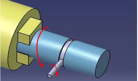
1.5.3 Pinch turning
Turrets are not only capable of processing different operations of a single job
(work-piece), but they also have the ability to process a single operation of that job at the
same time and hence, accelerate the process of machining [28, 29]. This feature is called
pinch turning. The mechanism of pinch turning is such that one of the cutting tools is one
depth of cut ahead of the other one [30]. The procedure is such that one cutting tool starts
removing the material from outside diameter of the part and the other cutting tool is idle at
the beginning, then after a very short hesitation, the other cutting tool starts the machining
procedure from the opposite side of the part. This is a great feature since it reduces multiple
movements of turrets and cutting tools to half and therefore, reduces processing times
considerably. Figure 3 shows the described mechanism for the procedure of pinch turning.
Two turrets can also work simultaneously on a single milling operation and provide a pinch
milling procedure. Pinch milling needs the two turrets to be equipped with live tooling
system. Pinch milling considers restrictions of turrets in terms of rotating along different
9
Upper cutting tool
Lower cutting tool Work-Piece Chuck
Figure 3: Application of pinch turning on a work-piece
1.5.4 Operation mode
Operations processed on a mill-turn machine are affected by the rotation of
work-piece and cutting tools mounted on turrets. There are two major types of operations, ones
which need the rotation of work-piece such as turning and facing, and those which require
the rotation of cutting tools such as milling and drilling. If two operations of the same job
are of the same mode (rotation of either work-piece or cutting tool), these operations can
be processed simultaneously on a single spindle. In other words, it is necessary for two
operations to have the same mode to be machined simultaneously by two different turrets
on a single spindle.
The mode of operations is in direct relation to the rotation of spindles. Turning
operations need the rotation of the spindle and hence, the workpiece held by it, whereas
milling operations need the rotation of the cutting tool and the spindle can be stationary.
Therefore, these two operations cannot be processed simultaneously on a single part.
However, in the world of multitask machining, turn-milling is a different type of
processing, in which both the work-piece mounted in the spindle and the live milling tool
rotates at the same time [31]. The reason to apply turn-milling instead of turning operations
is that turn milling provides less contact time between the cutting tool and the part,
therefore, there will be less heat produced during the machining process and the life of the
10
cutting tool will increase [32]. Figure 4 shows the procedure of turn-milling and how the
cutting tool and work-piece are rotated.
Figure 4: Application of turn-milling on a single work-piece
Limitations regarding the operation mode have a major effect on the final schedule
plan proposed for processing operations of a single job on a machine tool. Figure 5 shows
a sample part, which needs both turning and milling operations to be completely machined.
As can be seen, four different segments of the machined sample part are specified. Features
A and B, which include a hole drilling and a face milling are among those operations which
need the rotation of the cutting tool. On the other hand, features C and D, which are
processed through two different outside diameter turning operations, are among operations
which need the rotation of the spindle and the cutting tool is stationary. Therefore, features
B and C cannot be machined simultaneously, but features C and D could be processed at
one time if there is an available free turret for both of them.
Another concept related to the mode of operations is that each of the presented
features could be the result of multiple separate features. For instance, if we consider the
feature A of the part presented in Figure 5, we can see that this feature is a drilled hole,
which could be consist of four different operations; center drilling, drilling, boring and
reaming. Each of these operations required to achieve the final drilled feature is considered
11
Figure 5: A sample part with milling and turning features
1.5.5 Hard turning
Hard turning is one of the key features of multi-axis machine tools. It is the process
of cutting metals that are hardened to be used in some specific applications, and it could be
a good replacement for grinding operations [33]. By application of hard turning, parts can
be machined on the same setup and it provides a more agile and accurate type of machining
in compare with grinding operations [34-36]. Mill-turns have the capability to apply hard
turning, which is an important feature when integrating the concepts of single setup and a
faster and more accurate machining process.
There are some points which should be considered when applying hard turning on
a machine tool. The most important point is that the machine tool itself should be rigid
enough to handle the process of hard turning. The rigidity of the hardened part and the
cutting angle applied for this process creates a considerable amount of stress. Therefore,
the machine tool itself should be capable of handling the procedure. Another key feature,
which has to be considered is the cutting tool used for material removal. The cutting tool
must be tough enough to stand high temperatures and not to get worn. The third element to
be taken into account is the accurate control over the machining procedure and parameters.
The material removal rate and the speed at which the spindle is turning has to be adjusted
accordingly.
A
12
1.6 Process planning for parallel machines
General process planning and feature recognition of mill-turns have been
introduced to create a connection between aided design (CAD) and
computer-aided manufacturing (CAM) systems. Process planning provides a set of procedures and
instructions to accomplish the procedure of machining the part [37]. Based on the designed
features and specifications of each part a process plan is created.
Process planning on mill-turns considers the detailed design specifications of a
work-piece. It applies an automated computerized system, which is referred as CAPP, and
specifies the following [8, 10]:
1/Types of machining operations/features required for the metal cutting procedures.
At this level, different operations/features of a part, which should be processed to complete
the procedure of machining the part are identified. This information is recorded in the
system to be used in future steps of the planning module. When features are recognized,
complementary data regarding the planning mode are integrated into the system. To do so,
requirements such as precedence relationships between operations, the location where the
work-piece is going to be processed and different operations needed to process a feature
have to be considered.
2/Selection of proper cutting tool/machining unit and material removal rate. The
tools considered for machining each feature should be selected based on that specific
operation. Some extra features of cutting tools such as heat resistance and its rigidity should
also be taken into account. There will be a link between the proper cutting tools used for
machining procedures and the rate at which material will be removed to achieve a feasible
planning scheme.
3/ Feasible sequence for processing each feature. A valid process plan considers the
sequence in which different features of the part will be processed. In order to deliver a final
product, operations required to complete a part have to be processed in a predefined
13
4/Machining parameters, which affect the cutting procedures have to be specified.
Attributes such as cutting speed and depth of cut are key parameters, which have to be
considered. In addition, possible tool path for each feature needs to be defined.
1.7 Significance and research motivation
Considering how mill-turns are fast and reliable processing parts in an accurate
manner and a very short time makes them a suitable choice for many production units.
They have many capabilities, which differentiate them from other milling or turning
machine tools. Some of these features are listed below:
- Mill-turns have the privilege to handle both milling and turning operations on one setup
[10]. This is an important feature because it can reduce handling of parts.
- Since spindles have access to each other, the movement of the work-pieces from one work
holding location to another is done automatically. In case both sides of the part need to be
machined, there is no need to stop the machine tool and change the setup [38].
- Automatic movements of parts remove the need for the operator’s action [7] and therefore
this could reduce the errors related to the operator.
- Parallel machining of a single part by different machining units, reduces the total
make-span. This is an important feature when machining more parts in a very limited time. This
feature can also reduce costs related to delays.
- Parallel machining of different parts at the same time is also a considerable feature when
different products are planned to be machined and the total make-span of all parts is a key
factor.
There has been a tremendous attention from manufactures to the applications of mill-turns
and simultaneous machining. There is limited research done in this area and most of the
key features and aspects are not fully covered. The main motivation of this thesis is to
14
to address the problem of scheduling operations on mill-turns by considering more realistic
assumptions.
The second motivation of this thesis is to provide a mathematical model, which is
capable enough to present most of the features and advantages regarding the application of
parallel machines. Finally, since the problem at hand is computationally NP-complete [39],
developing a creative algorithm to solve larger sets of the problem which is most likely to
be the case, in reality, constitute the third motivation of this thesis.
1.8 Research outline
The second section of this thesis contains a detailed literature review. In the third
chapter, the Mixed Integer Linear Programming (MILP) model with an illustrated example
is presented. The fourth chapter, explains the heuristic algorithm and steps involved in
creating feasible solutions. The fifth chapter includes the case studies and computational
results obtained through testing of the mathematical model and the simulated annealing
15
CHAPTER 2: LITERATURE REVIEW
2.1 Problem statement
In this thesis, the problem of scheduling different Jobs on multitasking machine
tools is considered. Jobs are simply products or parts, which are consist of a different set
of operations. The goal is to create a schedule for machining operations of different jobs such that minimum total completion time is achieved. The type of machines considered for
the scheduling problem is multitasking machine tools known as mill-turns with
dual-spindle and dual-turret configuration. The machine tools considered in this thesis have the
capacity to perform multitasking on one part or multiple parts and therefore, there are
different from transfer machines. The final schedule also determines the sequence of
operations on different machine tools. Each operation has different processing times on
different machines, and there are some constraints related to the capacity of each machine
(turrets and spindles). Precedence relations among operations are considered as a vital part
of the scheduling problem. Finally, the capacity of turrets and spindles in terms of
simultaneous machining and concepts regarding the operation modes and single setup are
taken into account.
2.2 Literature review
In spite of the growing demand in the industry to apply parallel machining and
multitask machine tools, research done on scheduling so far is quite limited. The problem
of scheduling and sequencing operations on mill-turns has not been considered in
comparison with traditional parallel machine scheduling problems [40-42], which have
gained more attention in the literature. Unique features and capabilities of mill-turns along
with limitations will be explained in detail to further explore the physic of these machine
tools and identify possible areas of improvement.
Miller, P. C [43] and Miska. K. H. [44] introduce a new class of machine tools,
which are capable of machining parts in less amount of time and fewer setups. They fully
16
also discuss the key concepts of parallel machining and different configurations of
mill-turns.
Process planning and machining features have been considered by different authors
in the literature [45-47]. Levin and Dutta [8], discuss different elements of parallel
machining and multitasking, which affect the process planning for mill-turns. They
compare variant process planning versus process planning using optimization methods and
generative process planning. They also define the scope and development of Computer
Aided Process Planning (CAPP) for mill-turn machines.
Yip-Hoi and Dutta [38] use the information available from CAD models to
generate a valid process plan for machining different parts. To do so, they consider
geometric models of work-pieces to be machined. Considering the geometric features of
parts and in relation to CAD models, they present a scheme to determine the proper axis
for machining parts and also define the most suitable turning volumes. Feature recognition
has also been studied in the researches done by Tseng. Et al [48, 49], in the work of Li [50]
and Dutta. et al [51].
Azab and Naderi [52] propose a variable neighborhood search metaheuristic for the
problem of scheduling operations for simultaneous machining. The objective of the
proposed algorithm is to reach the minimum completion time for all operations. They do
not model the problem mathematically to define the capabilities and limitations of parallel
machines. Furthermore, the capacity of the machine tool to process a specific operation of
a single job by more than one cutting tool, mode of operations and concepts of single setup
is not considered in their study.
Levin and Dutta [10] study a detailed CAPP for parallel machines. They introduce
PMPS (Parallel Machine Planning System) for mill-turns to control removal of materials
from parts through the use of proper cutting tools and then sequencing operations on
machines. They also address concerns regarding tool path and parameters used for
machining. Levin and Dutta divide PMPS into two different categories; preprocessor and
planning module. In their defined preprocessor stage, permissible tolerances and depth of
cuts, precedence relations between operations, types of operations and best locations to
hold the part for machining purposes are determined. In the planning module defined by
17
relationships. The outcome of their PMPS system is a feasible sequence of operations with
assigned turrets and spindles for each operation.
Yip-Hoi and Dutta [7] discuss important components of simultaneous machining,
which are key to process planning. For that, they consider different properties of the part
such as shape, size and approach direction. Another issue, which is considered in their work
is exploring the most important components of mill-turns that are vital to the process
planning inputs. To address that issue, they study a template configuration of mill-turns in
detail and then they use instances of this template as an input for the process planning
procedure.
Yip-Hoi & Dutta [1] suggest a genetic algorithm (GA) to address the problem of
sequencing operations on mill-turns. They present a process plan to address geometric
features and limitations regarding mill-turn machines. The objective of Yip-Hoi and
Dutta’s algorithm is to achieve an optimum completion time for all operations. The offered
process plan, also considers the precedence relationships among operations, cutting tool
approach directions and machining parameters. However, no mathematical model is
proposed to further extend the problem for larger and more complicated instances.
Norman & Bean [2] present a small size model for the problem of scheduling
mill-turns and consider a shop where one work-piece is machined and scheduled. The objective
function is to minimize the total completion time. They assume a model in which all
operations are pre-assigned to spindles. The capacity of machines in terms of applying
multiple turrets for a single operation is not considered and since the model is considering
only one job to be machined concepts regarding the single setup are absent.
Chiu et al. [3] solve the problem of sequencing and scheduling operations on
parallel machines for a plant with only one part and one machine tool to be scheduled.
These researchers solve a model that is not linear. In their study, operations are scheduled
irrespective of the rotation of spindles and cutting tools and its effect on the final sequence.
Similar to the research done by Norman & Bean [2], since only one job and one machine
tool is considered for scheduling, no constraint is provided to prevent movement of part
from one machine to another.
A Mixed Integer Linear Programming model is developed by Naderi and Azab
18
manufacturing cell to minimize the overall completion time. They present a mathematical
model, which does not consider the mode of operations and how it could affect the number
of operations processed at the same time on a single spindle. Also, the capacity of turrets
to simultaneously process a specific operation of a single job on a single machine tool is
not considered.
2.3 Gap analysis
In order to summarize the related researches done in the area of multitasking and
machine scheduling, a synthesis matrix has been provided. Table 1 presents these findings
along with a brief description of the solution approach and assumptions, which are taken
to tackle the scheduling/sequencing problem.According to the literature, unlike the general
unrelated parallel machine scheduling problem [53-56] the research done to date in the area
of scheduling mill-turns is limited to simplistic problems and assumptions where a few
parts to be machined. However, this is not the case for most of the manufacturing plants in
which there might be different parts and multiple machine tools used for processing them
[57]. To the knowledge of the author, Naderi and Azab [39] were the only researchers who
recently provided a mathematical model in which more than one workpiece with a different
set of operations and machines were considered for the scheduling problem. They were
also assuming each operation has different machining time on different machine tools.
The assumption of having multiple jobs in which each job has a different number
of operations is a more realistic assumption in compare with traditional scheduling
problems in the literature in which a limited number of fixed jobs and machine tools are
considered. Moreover, the scheduling problem should fully resemble the features of these
machines to generate a plan, which is fairly close to their mechanism in reality. Machining
a part on a single setup and capacity of machine tools to process an operation with multiple
turrets are among these features, which were not addressed in the work of Chiu et al. [3],
Norman & Bean [2] and Naderi and Azab [39], who proposed a mathematical model to
19 Re m ar k s Theor et ica l i ss ue s rel at ed t o pr o ce ss pl ann ing and se quen ci n g oper at ions o n m il l-tu rns Theor et ica l i ss ue s of C A PP r el at ed to m il l-tu rns Extr act ing d at a fr o m ge om et ri c m ode ls and us ing the m t o cr ea te fea si b le m ac hi n ing pr oce ss es. S olu tion ap p roac h ed A n over al l gene ral ize d com p reh ens ive pr oce ss p lann ing A pr oce ss pl ann ing sys te m f o r par al lel m achi n es A C om put er A ided Proc ess P lann ing appr o ac h for m il l-tur n m achi nes Cons tr ain ts Pre ce denc e rel at ions, sur fa ce fi n ish inf o rm at ion, tol er an ce s Pre ce denc e rel at ions, g eom et ri c inf o rm at ion, oper at ion m ode Ma ch inab le vol u m es , w or k - pi ec e or ien ta ti o n, int er na l a nd ext er na l r em ova l rat e Ob je ctive fun
ction - - -
Mat he m a ti cal m ode l - - - Pr ob lem tac k led G ene ra l pr oce ss pl ann ing pr obl em Feat u re rec og ni ti on C al cu la ti on of m ac h in ing axi s and m ac h in ing vol u m es Ar tic le Le vin and Dutta [8 ] Yip
-Hoi a
nd
Dutta
[7
]
Yip
-Hoi a
20 Re m ar k s U se of com put er s in t h e a u to m at ion of pr oce ss pl ann ing (C A PP )f o r pa ra ll el m ac h ine t oo ls O nl y one par t is sc hedu led , m ul ti ta ski n
g on a
si ng le op er at ion is not co nsi der ed, no m at he m at ic al m ode l Schedu li n
g j
o bs w it hou t cons ider ing oper at ion m ode, conc ep ts of s ing le se tup , m ul ti tas k ing
on a s
ing le oper at ion S olu tion ap p roac h ed A gene rat ive C om pu ter A ided Proc ess P lann ing sys tem G ene ti c A lgor it h m var iabl e nei ghb or ho od se ar ch Cons tr ain ts Pre ce denc e rel at ions, ea rl ies t st ar t and f in ish ti m e o f oper at ions Pre ce denc e rel at ions, geom et ri c inf o rm at ion, oper at ion m ode, appr o ac h di re ct ion Pre ce denc e rel at ions, ca pac it y of ea ch tur ret , ca p ac it y of ea ch s p ind le Ob je ctive fun ction - Mi n. C Mi n. C m ax M athem atic al m od el - - - Pr ob lem tac k led C om pu ter A ided Proc ess Pla nn ing pr obl em Schedu li n g Schedu li n g Ar tic le Le vin and Dutta [10 ] Yip -Hoi
and Dutta
21 Re m ar k s A si ng le job, m ul ti ta ski n
g on a
si ng le op er at ion an d conc ep ts of s ing le se tup i s not cons ide red Schedu li n g a job w it hou t co nsi der ing : oper at ion m ode, si n gl e se tup , and m ul ti ta ski n
g on a
si ng le op er at ion Schedu li n
g j
o bs w it hou t co nsi der ing : oper at ion m ode, si n gl e se tup , m ul ti tas k ing on a s in gl e ope rat ion This t hes is cons ide rs al l of t he p rev iou sl y cons ider ed c o nst ra int s, pl us al l t h e m ent ion ed gap i n the l it er at ur e s o far S olu tion ap p roac h ed G ene ti c Al gor it h m G ene ti c Al gor it h m G A , SA , It er at ed G ree dy A lgor it hm , A rt if ici al I m m un e al go ri th m , I te rat ed Local S ea rch Sim u la ted A nnea li ng Cons tr ain ts Pre ce denc e r el at ions, ca pac it y of t u rr et an d spi nd le, oper at ion m ode Pre ce denc e r el at ions, ca pac it y of ea ch tur ret Pre ce denc e r el at ions, ca pac it y of ea ch tur ret , ca p ac it y of ea ch spi n dl e Pre ce denc e rel at ions, ca pac it y of ea ch tur ret and spi n dl e, m ul ti ta ski n
g on a
22
2.4 Research contributions
There are many features, which should be considered when modeling mill -turns.
Some of these features are basic concepts related to the mechanism of the mill-turns and
constitute the overlap in previously proposed models in the literature. These concepts
include precedence relationships, capacities of turrets, limitations of spindles, and
constraints related to start and finish times of operations according to their processing
times. There are some key areas that have not received enough attention in the literature
such as the concept of the operation mode, pinch turning, and single setup.
Mode of operations and how it can affect the final schedule plan is considered in
this work. The mode of operation and its relation with process planning of mill-turns could
be found in some of the researches done in the literature but the concept of operation mode
has not received enough attention in the literature for the scheduling problem.To the
author’s knowledge, the ability of multiple turrets to simultaneously process a specific
operation of a single job is another area, which has not been considered in the literature
yet. This feature is related to the application of pinch turning and its importance in
multi-tasking and it is fully discussed in section 1.5.3.
Machining the product from raw material to a finished part in only one setup,
which is known as “Done-in-One” concept, is another key factor, which has not gained
attention so far. This feature removes the movement of parts from one machine tool to
another and has a major effect on reducing costs related to part handling. These concepts
are core features, which have a considerable effect on the feasibility of the final proposed
plan. Each of them needs multiple constraints to resemble the mechanism of the machine
23
Therefore, the main contributions of this thesis can be summarized as follows:
- Creating a machine schedule in which the complete process of machining the
part/job from raw material to a finished product is done on a single setup.
- Defining a rigorous mathematical model in which simultaneous machining of
different operations of a single job is allowed based on concepts related to
operations mode.
- Processing multiple operations of a single job on a single spindle simultaneously
by using different turrets.
- Machining a single operation of a single work-piece (part) by multiple turrets at the
same time.
2.5 Solution approaches compare to the literature
The main focus of the previous studies done in the literature has been on
computer-aided process planning and sequencing operations on mill-turns. Research done so far have
mainly focused on feature recognition, machining parameters and sequencing operations
with limited setups and available resources. However, there have been few attempts in the
literature to provide a model in order to tackle scheduling problems, and if so, there have
been few assumptions, which present the kinematics of mill-turns.
This thesis focuses on the scheduling problem with consideration of machine tool
features, limitations, and capacities. Constraints applied to propose a model in this work
could be divided into two sections. The first type considers parameters related to
multitasking and specific features of mill-turns. The second type though fully presents the
attributes related to the nature of tasks considered for scheduling. Precedence relations and
type of each operation are among these features. The solution approached in this thesis
could be compared with those research in the literature, which propose a mathematical
model to tackle the scheduling problem.The proposed model is linear, therefore, optimality
24
CHAPTER 3: METHODOLOGY
3.1 Model
The problem of scheduling operations on mill-turns is addressed by developing a
mixed integer linear programming model. The model optimizes the total make-span and
creates a feasible solution for scheduling operations on spindles and machines. The model
also assigns a feasible turret for processing each part. Solving the model creates an optimal
solution to schedule different set of operations on available machine tools. The model also
creates a sequence of operations for each job, taken into consideration all constraints and
capabilities regarding the used parallel machine tools. The mixed integer linear
programming model will consider:
- Jobs and operations with different processing times on different machine tools
- The number of turrets used for processing each operation of a specific job
- Capacity of spindles in terms of loading operations
- Capacity of spindles in terms of loading jobs
- Capacity of turrets in terms of machining multiple operations
- Restrictions regarding the operation mode
- Restrictions regarding precedence relations among operations
- Restrictions regarding assigning jobs and operations to a specific turret or
spindle
25
3.1.1 Assumptions
In order to develop the mathematical model, the following assumptions were made.
1. Each operation is assigned to one machine.
2. On a machine tool, an operation is assigned one spindle.
3. Spindle engagement determines the number of active turrets (N) engaged in
performing each operation, where N ≤ 2.
4. If a spindle is loading two operations simultaneously, those operations should be
the same type.
5. Each spindle can hold one job at a time.
6. Each job is loaded on one spindle at a time.
7. Each turret can process one operation of a job at a time.
8. Precedence relations among operations of each job must be satisfied.
9. No delay or pause is allowed between consecutive scheduled operations.
10.If a Job is assigned to a spindle as part of a setup on a machine tool, its operations
will also be assigned to the same spindle of the same setup on the same machine
tool. Parts are assumed to be processed on a single setup where only one spindle is
used and no movement of parts between machines is allowed.
26
3.1.2 Nomenclature
m total available machines i=1, 2…m
n total jobs to be scheduled j=1, 2…n
e spindle turret engagement e=1, 2
ki count of spindles of machine i k=1, 2
hi count of turrets of machine i h=1, 2
lj count of operations of job j l=1, 2… lj
𝑅𝑗,𝑙 precedence operations ofoperation l of job j
𝑆𝑗,𝑖 spindles, capable of loading job j on machine i
𝑇𝑗,𝑖 turrets, capable of processing job j on machine i
𝑃𝑗𝑙𝑖 machining time ofoperation l of job j on machine i
𝑁𝑗𝑙 number of turrets used for processing each operation at a time
𝑊𝑗𝑙𝑙′ binary parameter taking the value of 1 if operations l and l' of job j
27
3.1.3 Decision variables
Continuous decision variable
𝑆𝑡𝑗𝑙 start time of operation l of job j
Binary decision variables
𝐵𝑗𝑖
1 if job j is processed on machine 𝑖, 0otherwise
𝐵′
𝑗𝑙𝑖 1 if operation l of job j isprocessed on machine 𝑖, 0 otherwise
𝐵′′𝑗𝑙𝑖𝑘𝑒 1 if operation l of job j is processed on spindle turret engagement e of
spindle k of machine 𝑖, 0 otherwise
𝐵′′′
𝑗𝑙𝑖ℎ 1 if operation l of job j is processed on turret h of machine 𝑖, 0 otherwise
𝐵′′′′𝑗𝑖𝑘 1 if job j is processed on spindle k of machine 𝑖, 0 otherwise
𝑍𝑗𝑙𝑗𝑙′ 1 if operation l of job j is processed after operation l' of job j, 0 otherwise
28
3.1.4 Objective function and constraints
The objective function for the MILP model is to minimize the total completion times of
all operations on all machines:
Min 𝐶𝑚𝑎𝑥
where 𝐶𝑚𝑎𝑥 is the maximum completion time. The model considers all of the available
machines and machining times of different operations and seeks for the best sequence of
operations on each machine to minimize the make-span.
Eq. (1) and Eq. (2) are provided to ensure that each operation is processed by one
spindle turret engagement, one spindle, and one machine. The parameter e defines the
capacity of the spindle in terms of loading different operations. Assuming both of the
available turrets work on a single operation, at any time, spindles have the capacity to load
maximum two operations.It is necessary to provide a constraint for the model so that at
any time each operation would only be scheduled on one machine and spindle. If there is
only one operation being processed on a spindle, the parameter e takes the value of one and
if two operations are simultaneously being processed on a single operation at a time, then
e takes the value of two.
∑ ∑ ∑ 𝐵′′𝑗𝑙𝑖𝑘𝑒
𝑘𝜖𝑆𝑗,𝑖
2
𝑒=1 𝑚
𝑖=1
= 1 ∀𝑗, 𝑙 (𝟏)
∑ 𝐵′ 𝑗𝑙𝑖 𝑚
𝑖 =1
= 1 ∀𝑗, 𝑙 (𝟐)
Eq. (3) and Eq. (4) assign each job, which is consist of a different set of operations to one
machine and spindle. As discussed in section 2.1, each job is consist of different operations
and number of operations for each job is different with another. The model prevents
scheduling of a single job at two different work-holding locations at a time. Hence, it is
necessary to provide two different constraints, one for allocation of the job to the spindle
29
∑ ∑ 𝐵′′′′𝑗𝑖𝑘 𝑘𝜖𝑆𝑗,𝑖
𝑚
𝑖=1
= 1 ∀𝑗 (𝟑)
∑ 𝐵𝑗𝑖 𝑚
𝑖=1
= 1 ∀𝑗 (𝟒)
Eq. (5) defines the number of turrets used for processing operations of each job. N is the
parameter, which defines the number of turrets working on a specific operation. Some
operations like turning, have the capacity to be processed by two turrets to achieve a faster
pace in the machining procedure. Therefore, N is provided to define this major capacity of
mill-turns, which has an important impact on the final schedule created.
∑ ∑ 𝐵′′′
𝑗𝑙𝑖ℎ ℎ𝜖𝑇𝑗,𝑖
𝑚
𝑖=1
= 𝑁𝑗𝑙 ∀𝑗, 𝑙 (𝟓)
Eq. (6) and Eq. (7) prevent simultaneous machining of two operations of the same job if
they are not the same type of operations. This constraint is related to the limitations
regarding the rotation of spindles. As discussed in section 1.5.4, some operations need the
rotation of the work-piece and others need the rotation of the cutting tool, therefore, these
two types of operations cannot be scheduled together and should not have an overlap in the
final schedule created. Another point, which needs to be considered is that each feature
needed to complete the machining process could itself be consist of multiple operations. In
this work, each operation is considered separately and has its unique mode.
𝑆𝑡𝑗𝑙 − 𝑆𝑡𝑗𝑙′ ≥ 𝐵′′𝑗𝑙′𝑖𝑘𝑒′. 𝑃𝑗𝑙′𝑖 − 𝑀(1 − 𝑍𝑗𝑙𝑗𝑙′) − 𝑀(1 − 𝐵′′𝑗𝑙′𝑖𝑘𝑒′) − 𝑀(1 − 𝐵′′𝑗𝑙𝑖𝑘𝑒)
∀𝑗, 𝑙 < 𝑙′ ∋ 𝑊
𝑗𝑙𝑙′ = 1 , 𝑒, 𝑒′, 𝑖 , 𝑘 ∈ {𝑆𝑗,𝑖} (𝟔)
𝑆𝑡𝑗𝑙′ − 𝑆𝑡𝑗𝑙 ≥ 𝐵′′𝑗𝑙𝑖𝑘𝑒. 𝑃𝑗𝑙𝑖− 𝑀(𝑍𝑗𝑙𝑗𝑙′) − 𝑀(1 − 𝐵′′𝑗𝑙′𝑖𝑘𝑒′) − 𝑀(1 − 𝐵′′𝑗𝑙𝑖𝑘𝑒)
∀𝑗, 𝑙 < 𝑙′ ∋ 𝑊
30
Eq. (8-11) are provided to allow for simultaneous machining of two different operations of
the same job only if they are the same type (either rotation of spindle or the cutting tool).W
is the parameter, which defines if two operations are of the same type or not. If two
operations of the same job are of the same type, W takes the value of zero otherwise it takes
the value of one.
𝑆𝑡𝑗𝑙 − 𝑆𝑡𝑗𝑙′ ≥ −𝑀(1 − 𝑍𝑗𝑙𝑗𝑙′) − 𝑀(1 − 𝐵′′𝑗𝑙′𝑖𝑘𝑒′) − 𝑀(1 − 𝐵′′𝑗𝑙𝑖𝑘𝑒)
∀𝑗, 𝑙 < 𝑙′ ∋ 𝑊
𝑗𝑙𝑙′ = 0 , 𝑒, 𝑒′, 𝑖, 𝑘 ∈ {𝑆𝑗,𝑖} 𝑒 ≠ 𝑒′ (𝟖)
𝑆𝑡𝑗𝑙′ − 𝑆𝑡𝑗𝑙 ≥ −𝑀(𝑍𝑗𝑙𝑗𝑙′) − 𝑀(1 − 𝐵′′𝑗𝑙′𝑖𝑘𝑒′) − 𝑀(1 − 𝐵′′𝑗𝑙𝑖𝑘𝑒)
∀𝑗, 𝑙 < 𝑙′ ∋ 𝑊
𝑗𝑙𝑙′ = 0 , 𝑒, 𝑒′, 𝑖, 𝑘 ∈ {𝑆𝑗,𝑖} 𝑒 ≠ 𝑒′ (𝟗)
𝑆𝑡𝑗𝑙 − 𝑆𝑡𝑗𝑙′ ≥ 𝐵′′𝑗𝑙′𝑖𝑘𝑒′. 𝑃𝑗𝑙′𝑖 − 𝑀(1 − 𝑍𝑗𝑙𝑗𝑙′) − 𝑀(1 − 𝐵′′𝑗𝑙′𝑖𝑘𝑒′) − 𝑀(1 − 𝐵′′𝑗𝑙𝑖𝑘𝑒)
∀𝑗, 𝑙 < 𝑙′ ∋ 𝑊
𝑗𝑙𝑙′ = 0 , 𝑒, 𝑒′, 𝑖, 𝑘 ∈ {𝑆𝑗,𝑖} 𝑒 = 𝑒′ (𝟏𝟎)
𝑆𝑡𝑗𝑙′ − 𝑆𝑡𝑗𝑙 ≥ 𝐵′′𝑗𝑙𝑖𝑘𝑒. 𝑃𝑗𝑙𝑖− 𝑀(𝑍𝑗𝑙𝑗𝑙′) − 𝑀(1 − 𝐵′′𝑗𝑙′𝑖𝑘𝑒′) − 𝑀(1 − 𝐵′′𝑗𝑙𝑖𝑘𝑒)
∀𝑗, 𝑙 < 𝑙′ ∋ 𝑊
𝑗𝑙𝑙′ = 0 , 𝑒, 𝑒′, 𝑖, 𝑘 ∈ {𝑆𝑗,𝑖} 𝑒 = 𝑒′ (𝟏𝟏)
Eq. (12) and Eq. (13) are provided to prevent spindles from holding more than one job at
any time.
𝑆𝑡𝑗𝑙 − 𝑆𝑡𝑗′𝑙′ ≥ 𝐵′′′′𝑗′𝑖𝑘. 𝑃𝑗′𝑙′𝑖 − 𝑀(1 − 𝑍𝑗𝑙𝑗′𝑙′) − 𝑀(1 − 𝐵′′′′𝑗′𝑖𝑘) − 𝑀(1 − 𝐵′′′′𝑗𝑖𝑘)
∀𝑗 < 𝑗′, 𝑙, 𝑗 < 𝑛, , 𝑙′, 𝑖 , 𝑘 ∈ {𝑆