University of South Carolina
Scholar Commons
Theses and Dissertations
1-1-2013
New Ruthenium and Osmium Carbonyl Cluster
Complexes With Main Group Bridging Ligands
Having Unusual Structures and Bonding
Yuwei Kan
University of South Carolina
Follow this and additional works at:https://scholarcommons.sc.edu/etd
Part of theChemistry Commons
This Open Access Dissertation is brought to you by Scholar Commons. It has been accepted for inclusion in Theses and Dissertations by an authorized administrator of Scholar Commons. For more information, please contactdillarda@mailbox.sc.edu.
Recommended Citation
NEW RUTHENIUM AND OSMIUM CARBONYL CLUSTER COMPLEXES WITH MAIN
GROUP BRIDGING LIGANDS HAVING UNUSUAL STRUCTURES AND BONDINGby
Yuwei Kan
Bachelor of Engineering Jilin University, 2008
Submitted in Partial Fulfillment of the Requirements
For the Degree of Doctor of Philosophy in
Chemistry
College of Arts & Sciences
University of South Carolina
2013
Accepted by:
Richard D. Adams, Major Professor
Hans-Conrad Zur Loye, Committee Member
Qian Wang, Committee Member
Timir Datta, Committee Member
ii
iii
ACKNOWLEDGEMENTS
I would like to express my most sincere gratitude and appreciation to my advisor,
Professor Richard Adams, for his guidance, patient and support throughout my research
over the past five years. His dedication, passion and expertise in cluster chemistry made
me always want to think and explore more. My sincere appreciation is extended to my
committee members: Prof. Hans-Conrad Zur Loye, Prof. Qian Wang and Prof. Timir
Datta for their time and valuable advice to my research.
I would like to thank Prof. Vitaly Rassolov, Prof. Michael B. Hall (Texas A&M
University) and Dr. Eszter Trufan (Texas A&M University) for the DFT calculations on
the Ru4(CO)12(μ4-GePh) and [Ru3(CO)8(μ3-CMe)(μ-H)2(μ3-H)]2. I am also thankful to
Qiang Zhang, who is a great companion in Adams group and my life (my dear husband),
for his help with crystals that were difficult to handle and the DFT calculations on the
OsAu and OsBi compounds.
I wish to thank the past and present members of Adams group. Dr. Minglai Fu
and Dr. Eszter Trufan for guiding my first steps in research; Gaya Elpitiya for the best
time we had in the lab and the most precious friendship; Dr. Mingwei Chen, Yuen Onn
Wong and Joeseph Kiprotich for being great teammates; and the new members Jonathan
Tedder and Dr. Juliet Hahn for making me realize how much I have learnt.
These years wouldn’t have been as great if without the support from my family. I
wish to express my deepest gratitude to my dear husband, Qiang Zhang, for being
iv
I would not be able to done all of this without you. I thank my son, Jason Zhang, for
being a good boy and not making too much trouble; my mom Wanhua Li, dad Qiang Kan
and mother in-law Xuehua Na for helping me take care of my son and being so
supportive for my research. Thank my grandfather, Xueda Li, for your understanding and
support to study in the US: I miss you so much. Thank my precious daughter: we’ll be
able to see you in one month.
I would also like to thank my friends Xin Li, Nan Jiang, Suning Wang, Yun Wu,
Xiaofang Zhang, Pei Tang, Hong Guan, Xiaoguang Ma, Di Song, Chen Zhao, Zhichao
Shan, Xiaolong Bai, Ron Parker and Marianne Parker for all the wonderful time we spent
together. Especially I would like to thank Gaya Elpitiya and Prasanna Malinda Witharana
for the delicious Sri Lankan food.
Last but not least, I would like to thank National Science Foundation for the
v
ABSTRACT
The reaction of IrRu3(CO)13(µ-H), 2.1 with HSnPh3 in hexane solvent at reflux
has provided the new mixed metal cluster compounds Ir2Ru2(CO)11(SnPh3)(µ-H)3, 2.2
and IrRu3(CO)11(SnPh3)3(µ-H)4, 2.3 containing SnPh3 ligands. Compound 2.2 which was
obtained in low yield (3%)contains a closed cluster having two iridium and two
ruthenium atoms, one SnPh3 ligand and three bridging hydride ligands.Compound 2.3
has a butterfly structure for the four metal atoms with three SnPh3 ligands and four
bridging hydride ligands around the periphery of the cluster. When compound 2.3 was
heated to 97 oC for 30min, IrRu3(CO)9(μ-η2-C6H5)(μ4-SnPh)2(μ-SnPh2), 2.4 was formed
by cleavage of phenyl rings from the SnPh3 ligands in low yield. Compound 2.4 contain
square IrRu3 clusters of the metal atoms with quadruply bridging SnPh ligands on
opposite sides of the cluster, one bridging SnPh2 ligand on one of the Ir-Ru bonds and
also a rare η2-bridging phenyl ligand.
The new compound IrRu3(CO)11(GePh3)3(µ-H)4, 3.1 was obtained in 64% yield
from the reaction of IrRu3(CO)13(μ-H) with HGePh3 at room temperature. Compound 3.1
is the Ge analog of compound 2.3, whichcontains an open cluster of one iridium and
three ruthenium atoms with three GePh3 ligands and four hydride ligands. When the
reaction was performed at hexane reflux for 10 min a second minor
Ir2Ru2(CO)11(GePh3)(μ-H)3, 3.2 was formed. Compound 3.2 is two iridium atoms and
two ruthenium atoms in a tetrahedral structure which must have formed by some
vi
compounds: IrRu3(CO)10(μ-η2-C6H5)(μ4-GePh)2, 3.3 and IrRu3(CO)9(μ-η2-C6H5)(μ4
-GePh)2(μ-GePh2), 3.4 were formed by cleavage of phenyl rings from the GePh3 ligands.
Compound 3.3 and 3.4 contain square IrRu3 clusters of the metal atoms with quadruply
bridging GePh germylyne ligands on opposite sides of the cluster. Both compounds also
contain a rare η2-bridging phenyl ligand. Compound 3.4 was found to react with
dimethylacetylenedicarboxylate DMAD to yield new compound IrRu3(CO)9([μ4
-Ge(Ph)C(CO2Me)C(CO2Me)](μ-GePh2)2, 3.5 by addition of DMAD to one of the
bridging germylyne ligands. In the process the bridging phenyl ligand was transferred to
the other bridging germylyne ligand to form a bridging germylene ligand.
The compounds Ru4(CO)12(GePh3)2(μ-H)4, 4.1 and Ru4(CO)12(SnPh3)2(μ-H)4, 4.2
were obtained from the reactions of Ru4(CO)13(μ-H)2 with HGePh3 and HSnPh3,
respectively. Both compounds contain a nearly planar butterfly structure for the four
metal atoms with two GePh3 / SnPh3 ligands and four bridging hydride ligands around the
periphery of the cluster. When heated, 4.1 and 4.2 were converted into the complexes
Ru4(CO)12(μ4-EPh)2, 4.3, E = Ge, and 4.4, E = Sn, by cleavage of two phenyl groups
from each of the GePh3 ligands. Compounds 4.3 and 4.4 contain square planar
arrangements of the four ruthenium atoms with quadruply bridging germylyne and
stannylyne ligands on opposite sides of the square plane. The bonding and electronic
transitions of 4.3 were analyzed by DFT computational analyses.
The electronically unsaturated complex [Ru3(CO)8(μ3–CMe)(μ–H)2(μ3–H)]2, 5.1
was obtained by silica gel induced reaction of Ru3(CO)8(μ3–CMe)(μ–H)3, 5.2. Compound
5.1 can be viewed as a dimer of the 46 electron fragment Ru3(CO)8(μ3–CMe)(μ–H)3, is
vii
Compound 5.1 exhibits a dynamical activity in solution that equilibrates two of the three
types of hydride ligands. Compound 5.1 reacts with 1,1–bis(diphenyphosphino)methane
to form the macrocyclic complex [Ru3(CO)7(μ3–CMe)(μ–H)3]2(μ–dppm)2, 5.3.
Compound 5.3 is a centrosymmetrical dimer linked by two bridging dppm ligands, each
phosphorus atom of the dppm is coordinated to a different Ru3 cluster. However,
Ru3(CO)7(μ3-CMe)(μ-H)3(μ-dppm), 5.4, was obtained from the reaction of Compound
5.2 with dppm.
Reactions of Os3(CO)10(NCMe)2 with HGePh3 have yielded the compounds
Os3(CO)10(NCMe)(GePh3)(μ-H), 6.1 and Os3(CO)10(GePh3)2(μ-H)2, 6.2 by the sequential
replacement of the NCMe ligands and the oxidative addition of the GeH bonds of one
and two HGePh3 molecules, respectively, to the osmium atoms of the cluster. Compound
6.2 exists as two isomers in solution at low temperatures which interconvert rapidly on
the 1H NMR time scale at room temperature. When heated, 6.1 was transformed into the
pentaosmium complex Os5(CO)17(μ-GePh2), 6.3 which exhibits a planar raft structure
with one bridging GePh2 ligand. Compound 6.1 reacts with the compound PhAu(PPh3) to
yield the compound Os3(CO)8(μ-CO)(μ-O=CPh)(μ-GePh2)(μ-AuPPh3), 6.4 which
contains a bridging O=CPh ligand and a Au(PPh3) group that bridges an Os-Ge bond, and
compound PhOs4(CO)13(µ-GePh2)(µ-AuPPh3), 6.6 which contains four osmium atoms in
a butterfly arrangement with one bridging GePh2 ligand, one bridging AuPPh3 ligand and
one σ-bonded phenyl ligand to one of the osmium atoms. A minor product,
Os(CO)4(GePh3)(AuPPh3), 6.5 was also obtained in this reaction. Compound 6.4 was also
obtained from the reaction of 6.1 with CH3Au(PPh3). Compound 6.4 reacted with PhC2Ph
viii
contains a novel bridging oxa-metallacycle formed by the coupling of PhC2Ph to the
bridging O=CPh ligand 6.4 and another example of a Au(PPh3) group that bridges an
Os-Ge bond. The bonding of the bridging Au(PPh3) group to the Os – Ge bonds in 6.4 and
6.7 was investigated by DFT computational analyses.
Three new compounds were obtained from the reaction of Os3(CO)10(NCMe)2,
7.1 with BiPh3 in a methylenechloride solution at reflux. These have been identified as
Os3(CO)10(μ3-C6H4), 7.2, Os3(CO)10Ph(μ-η2-O=CPh), 7.3, and HOs6(CO)20(μ-η2
-C6H4)(μ4-Bi), 7.5. A fourth product HOs5(CO)18(μ-η2-C6H4)(μ4-Bi), 7.4 was also
obtained from the reaction of Os3(CO)11(NCMe) with BiPh3. Cleavage of the phenyl
groups from the BiPh3 was the dominant reaction pathway and two of the products 7.2
and 7.3 contain rings but no bismuth. Each of the new compounds was characterized
structurally by single-crystal X-ray diffraction methods. Compound 7.2 contains a triply
bridging benzyne (C6H4) ligand that exhibits a pattern of alternating long and short C – C
bonds that can be attributed to partial localization of the π-bonding in the C6 ring. The
localization in the π-bonding was supported by DFT calculations. Compound 7.3 contains
a triangular cluster of three osmium atoms with a bridging benzoyl ligand and a
terminally coordinated phenyl ligand. Compound 7.5 contains six osmium atoms divided
into two groups of four and two and the two groups are linked by a spiro-bridging
bismuth atom. The group of two osmium atoms contains a bridging C6H4 ligand. When
heated, compound 7.3 was converted into 7.2 and the compound Os3(CO)10(μ-η2
ix
TABLE OF CONTENTS
Acknowledgements………....iii
Abstract………...v
List of Tables………..xi
List of Figures………...xiii
List of Schemes………xvii
Chapter One: Introduction ………...1
References………..21
Chapter Two: New Iridium-Ruthenium-Tin Cluster Complexes from the Reaction of HSnPh3 with HIrRu3(CO)13……….……25
References………..45
Chapter Three: Transformations of Triphenylgermyl Ligands in New Iridium-Ruthenium Carbonyl Cluster Complexes……...……..47
References………..76
Chapter Four: New Tetraruthenium Carbonyl Complexes Containing Germyl and Stannyl Ligands from the Reactions of Ru4(CO)13(µ-H)2 with HGePh3 and HSnPh3………..79
References………118
Chapter Five: Bonding and Reactivity in the New Electronically Unsaturated Hydrogen-Bridged Dimer [Ru3(CO)8(μ3-CMe)(μ-H)2(μ3-H)]2………...120
References………146
ix
References………193
Chapter Seven: Cleavage of Phenyl Groups from BiPh3.
The Reactions of Os3(CO)10(NCMe)2 with BiPh3.………...196
References………221
xi
LIST OF TABLES
Table 2.1 Crystallographic Data for Compounds 2.2, 2.3 and 2.4 ...41
Table 2.2 Selected intramolecular angles and bond distances for compound 2.2 ...42
Table 2.3 Selected intramolecular angles and bond distances for compound 2.3 ...43
Table 2.4 Selected intramolecular angles and bond distances for compound 2.4 ...44
Table 3.1 Crystallographic Data for Compounds 3.1 and 3.2 ...69
Table 3.2 Crystallographic Data for Compounds 3.3, 3.4 and 3.5 ...70
Table 3.3 Selected intramolecular angles and bond distances for compound 3.1 ...71
Table 3.4 Selected intramolecular angles and bond distances for compound 3.2 ...72
Table 3.5 Selected intramolecular angles and bond distances for compound 3.3 ...73
Table 3.6 Selected intramolecular angles and bond distances for compound 3.4 ...74
Table 3.7 Selected intramolecular angles and bond distances for compound 3.5 ...75
Table 4.1 Crystallographic Data for Compounds 4.1, 4.2 and 4.3 ...114
Table 4.2 Selected intramolecular angles and bond distances for compound 4.1 ...115
Table 4.3 Selected intramolecular angles and bond distances for compound 4.2 ...116
Table 4.4 Selected intramolecular angles and bond distances for compound 4.3 ...117
Table 5.1 Crystallographic Data for Compounds 5.1, 5.3 and 5.4 ...142
Table 5.2 Selected intramolecular angles and bond distances for compound 5.1 ...143
Table 5.3 Selected intramolecular angles and bond distances for compound 5.3 ...144
Table 5.4 Selected intramolecular angles and bond distances for compound 5.4 ...145
xii
Table 6.2 Selected intramolecular angles and bond distances for compound 6.1 ...186
Table 6.3 Selected intramolecular angles and bond distances for compound 6.2 ...187
Table 6.4 Selected intramolecular angles and bond distances for compound 6.3 ...188
Table 6.5 Selected intramolecular angles and bond distances for compound 6.4 ...189
Table 6.6 Selected intramolecular angles and bond distances for compound 6.5 ...190
Table 6.7 Selected intramolecular angles and bond distances for compound 6.6 ...191
Table 6.8 Selected intramolecular angles and bond distances for compound 6.7 ...192
Table 7.1 Crystallographic Data for Compounds 7.2, 7.3, 7.5 and 7.6 ...216
Table 7.2 Selected intramolecular angles and bond distances for compound 7.2 ...217
Table 7.3 Selected intramolecular angles and bond distances for compound 7.3 ...218
Table 7.4 Selected intramolecular angles and bond distances for compound 7.5 ...219
xiii
LIST OF FIGURES
Figure 1.1 (Left) The ν3 tetrahedral structure of [Os20(CO)40]2-;
(Right) View of the metal core ...11
Figure 1.2 Effect of tin in the selective hydrogenation of
1,5,9-cyclododecatriene (CDT) using anchored monometallic
and bimetallic cluster catalysts ...12
Figure 1.3 Gas-phase ammoxidation and liquid-phase oxidation of 3-picoline ...13
Figure 1.4 Catalytic behavior of the bimetallic Re-Sb/Bi catalysts
with differenct Re-Sb ratio...14
Figure 1.5 Four phenyltin bridging mode to transition metal clusters ...15
Figure 2.1 An ORTEP diagram of H3Ru2Ir2(CO)11SnPh3, 2.2showing
40% probability thermal ellipsoids ...34
Figure 2.2 An ORTEP diagram of H4Ru3Ir(CO)11(SnPh3)3, 2.3 showing
30% probability thermal ellipsoids ...35
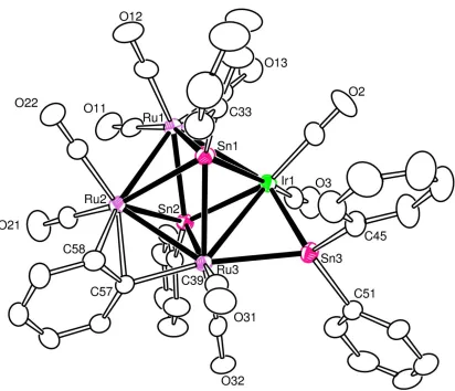
Figure 2.3 An ORTEP diagram of IrRu3(CO)9(μ-η2-C6H5)(µ-SnPh)2(µ-SnPh2),
2.4 showing 25% probability thermal ellipsoids...36
Figure 3.1 An ORTEP diagram of IrRu3(CO)11(GePh3)3(µ-H)4, 3.1 showing
30% probability thermal ellipsoids ...60
Figure 3.2 An ORTEP diagram of Ir2Ru2(CO)11(GePh3)(µ-H)3,3.2 showing
30% probability thermal ellipsoids ...61
Figure 3.3 An ORTEP diagram of IrRu3(CO)10(µ-η2-C6H5)(µ4-GePh)2, 3.3
showing 40% probability thermal ellipsoids...62
Figure 3.4 An ORTEP diagram of IrRu3(CO)9(µ-η2-C6H5)(µ4-GePh)2(µ-GePh2),
3.4 showing 20% probability thermal ellipsoids...63
Figure 3.5 An ORTEP diagram of
IrRu3(CO)9(µ-GePh2)2[µ4-Ge(Ph)C(CO2CH3)C(CO2CH3)], 3.5
xiv
Figure 4.1 An ORTEP diagram of Ru4(CO)12(GePh3)2(µ-H)4, 4.1
showing 30% probability thermal ellipsoids...94
Figure 4.2 An ORTEP diagram of Ru4(CO)12(SnPh3)2(µ-H)4,4.2
showing 20% probability thermal ellipsoids...95
Figure 4.3 An ORTEP diagram of Ru4(CO)12(μ4-GePh)2, 4.3 showing
20% probability thermal ellipsoids ...96
Figure 4.4 A molecular orbital energy level diagram in eV for compound
4.3 and selected molecular fragments ...97
Figure 4.5 Selected molecular orbitals for the Ru4(CO)12 fragment
of compound 4.3 ... 98-99
Figure 4.6 Selected molecular orbitals for compound 4.3 ... 100-102
Figure 4.7 UV–vis spectrum of 4.3 in methylene chloride solution ...103
Figure 4.8 TD-PBEsolcalculated UV–vis spectrum of compound 4.3 ...104
Figure 5.1 Examples of unsaturated polynuclear metal complexes
containing bridging hydride ligands ...131
Figure 5.2 Electron impact mass spectrum of compound 5.1 ...132
Figure 5.3 An ORTEP diagram of the molecular structure of Ru6(CO)16(μ3–CMe)2(μ–H)4(μ3–H)2, 5.1 showing 30%
thermal ellipsoid probability ...133
Figure 5.4 Schematic representations of the monomer, the intermediate
with the Ru(3)−Ru(3′) bond, and the dimer, showing bond distances of the optimized structures and the relative Gibbs free energies
of the systems ...134
Figure 5.5 Selected molecular orbital contour diagrams of 5.1 and fragment ...135
Figure 5.6 An ORTEP diagram of the molecular structure of
[Ru3(CO)7(μ3–CMe)(μ–H)3]2(μ–dppm)2, 5.3, showing 30%
thermal ellipsoid probability ...136
Figure 5.7 A stack of plots of the 1H NMR spectra of compound
5.1 at various temperatures in the hydride region ...137
Figure 5.8 An ORTEP diagram of the molecular structure of
xv
ellipsoid probability ...138
Figure 6.1 An ORTEP diagram of the molecular structure of
Os3(CO)10(NCMe)(GePh3)(µ-H), 6.1 showing 30% thermal
ellipsoid probability ...166
Figure 6.2 An ORTEP diagram of the molecular structure of Os3(CO)10(GePh3)2(µ-H)2, 6.2 showing 30% thermal
ellipsoid probability ...167
Figure 6.3 Variable temperature 1H NMR spectra for compound
6.2 in CD2Cl2 solvent recorded in the high field region of the spectrum ...168
Figure 6.4 A 2D NOESY spectrum of compound 6.2 at -40 oC ...169
Figure 6.5 A 2D NOESY spectrum of compound 6.2 at -80 oC ...170
Figure 6.6 An ORTEP diagram of the molecular structure of
Os5(CO)17(µ-GePh2), 6.3 showing 30% thermal ellipsoid probability ...171
Figure 6.7 An ORTEP diagram of the molecular structure of Os3(CO)8(µ-CO)(µ-OCPh)(µ-GePh2)(µ-AuPPh3), 6.4
showing 30% thermal ellipsoid probability ...172
Figure 6.8 The highest occupied molecular orbital of compound 6.4 (Iso = 0.03) shows that a significant component of the orbital
is derived from a direct interaction between the Au and Ge atoms ...173
Figure 6.9 An ORTEP diagram of the molecular structure of Os(CO)4(GePh3)(AuPPh3), 6.5 showing 30% thermal
ellipsoid probability ...174
Figure 6.10 An ORTEP diagram of the molecular structure of PhOs4(CO)13(µ-GePh2)(µ-AuPPh3), 6.6 showing 30%
thermal ellipsoid probability ...175
Figure 6.11 An ORTEP diagram of the molecular structure of Os3(CO)7(µ-GePh2)(µ-AuPPh3)[µ-OCPhCPhCPh)],6.7
showing 20% thermal ellipsoid probability ...176
Figure 6.12 The HOMO and HOMO-2 of compound 6.7 (Iso = 0.03) s
how significant bonding interactions directly between the
Au and Ge atoms ...177
xvi
ellipsoid probability ...207
Figure 7.2 Diagrams of the HOMO and HOMO-2 with their energies
for compound 7.2 showing the -bonding in the C6H4 ring ...208
Figure 7.3 An ORTEP diagram of the molecular structure of PhOs3(CO)10(μ-η2-O=CPh), 7.3 showing 30% thermal
ellipsoid probability ...209
Figure 7.4 An ORTEP diagram of the molecular structure of Os6(CO)20(μ-η2-C6H4)(μ4-Bi)(-H), 7.5 showing 30%
thermal ellipsoid probability ...210
Figure 7.5 An ORTEP diagram of the molecular structure of Os3(CO)10(μ-η2-O=CPh)2, 7.6 showing 30% thermal
ellipsoid probability ...211
Figure 7.6 Selected electron densities at bond critical points calculated
xvii
LIST OF SCHEMES
Scheme 1.1 The mechanism for the catalytic process of hydrogenation of diphenylacetylene to (Z)-Stilbene by use of
Pt3Ru6(CO)20(µ3-PhC2Ph)(µ3-H)(µ-H) complex as catalysts ...16
Scheme 1.2 Range of Commodity and Specialty Chemicals That Can Be Derived from the Selective Partial Hydrogenation of
Cyclododecatriene (CDT) ...17
Scheme 1.3 Synthesis of Ir(COD)(CO)2EPh3 from the reaction of
[Ir(COD)Cl]2 with Ph3Eli and some transformation of Ir-E
cluster complexes, (E = Ge or Sn) ...18
Scheme 1.4 Ir3(CO)6(µ-GePh2)3(GePh3)3(Ph) is obtained by α-phenyl
cleavage from Ir3(CO)6(µ-CO)(µ-GePh2)2(GePh3)3 upon heating
under 110oC ...19
Scheme 1.5 Quadruply bridging EPh compoundsRu4(CO)10(µ4-EPh)2(µ-EPh2)2
and Ru4(CO)9(µ4-EPh)2(µ-EPh2)3 are obtainedfrom the reaction
of H4Ru4(CO)12 with excess Ph3EH in octane reflux ...20
Scheme 2.1 Ru3(CO)12, 2.5 reacts with Ph3SnH at 97 oC under hydrogen
atmosphere to yield Ru3(CO)9(SnPh3)3(μ-H)3, 2.6and
Ru3(CO)9(-SnPh2)3, 2.7. 2.6 can be converted to 2.7 by
heating to reflux in an octane solution ...37
Scheme 2.2 Rh4(CO)12, 2.8 reacts with Ph3SnH at room temperature
to yield 2.9. Reaction of 2.9 with Ph3SnH at reflux in
1,2-dichlorobenzene solvent yielded the complex 2.10 ...38
Scheme 2.3 The compounds 2.11, 2.12, 2.13, and 2.14 were obtained from the reaction of [Ru4(CO)12(µ-H)4] with Ph3SnH in
octane solvent at reflux (125 oC) ...39
Scheme 2.4 Compound 2.1 reactwith HSnPh3 to yield 2.2 and 2.3. 2.4 was formed when compound 2.3 was heated
to 97 oC for 30min ...40
Scheme 3.1 Compound 3.6, 3.7, and 3.8 are obtained from the reaction of
xviii
Scheme 3.2 Ir4(CO)12 react with HGePh3 under octane reflux to
yield Ir3(CO)5(GePh3)(µ-H)(µ-GePh2)3(µ3-GePh) and
Ir3(CO)6(GePh3)3(µ-GePh2)3 ...66
Scheme 3.3 Ir4(CO)12 react with HGePh3 under nonane reflux to
yield H4Ir4(CO)4(µ-GePh2)4(µ4-GePh)2...67
Scheme 3.4 IrRu3(CO)13(µ-H) reacts with HGePh3 to yield the
compound 3.1 and 3.2. Compound 3.1 was transformed into
3.3 and 3.4 upon heating to hexane reflux for 6h. Compound
3.4 reacts with dimethylacetylenedicarboxylate to yield
the new compound 3.5 ...68
Scheme 4.1 Four PhSn or PhGe bridging mode to transition metal ...105
Scheme 4.2 Ru5(CO)15(µ5-C) reacts with HGePh3 or HSnPh3 in
nonane reflux to yield Ru5(CO)11(µ-EPh2)4(µ5-C) ...106
Scheme 4.3 Rh4(CO)12 reacts with HSnPh3 in octane reflux to
yield Rh3(CO)6(SnPh3)3(µ-SnPh2)3. Triply bridging PhSn compound
Rh3(CO)3(SnPh3)3(µ-SnPh2)3(µ3-SnPh)2 is obtained when
Rh3(CO)6(SnPh3)3(µ-SnPh2)3 reacts with more HSnPh3 under 172oC ...107
Scheme 4.4 Re2(CO)8(µ-C6H11)(µ-H) reacts with HEPh3
(E = Ge or Sn) to yield Re2(CO)8(µ-EPh2)2 ...108
Scheme 4.5 Quadruply bridging EPh compounds
Ru4(CO)10(µ4-EPh)2(µ-EPh2)2 and Ru4(CO)9(µ4-EPh)2(µ-EPh2)3
are obtainedfrom the reaction of H4Ru4(CO)12
with excess Ph3EH in octane reflux ...109
Scheme 4.6 Bridging EPh2 ligands are formed by heating terminally EPh3 complexes .110
Scheme 4.7 IrRu3(CO)10(µ-C6H5)(µ4-GePh)2 and
IrRu3(CO)9(µ-C6H5)(µ4-GePh)2(µ-GePh2) are obtained by heating
IrRu3(CO)11(GePh3)3(µ-H)4 under hexane reflux ...111
Scheme 4.8 Ir3(CO)6(µ-GePh2)3(GePh3)3(Ph) is obtained by
α-phenyl cleavage from Ir3(CO)6(µ-CO)(µ-GePh2)2(GePh3)3
upon heating under 110oC ...112
Scheme 4.9 Ru4(CO)13(µ-H)2 readily reacts with HEPh3 to yield 4.1 or 4.2. 4.3 or 4.4 are obtained from 4.1 or 4.2 under
hexane reflux, respectively ...113
xix
Scheme 5.2 . Formation of 5.3 from 5.1 ...140
Scheme 5.3 Formation of 5.4 from 5.2 ...141
Scheme 6.1 Phenyl cleavage process on Ir-Bi-E cluster ...178
Scheme 6.2 Phenyl cleavage process on (µ-H)3Ru3(CO)9(EPh3), E = Ge or Sn ...179
Scheme 6.3 Phenyl cleavage from Ir3(CO)6(µ-CO)(µ-GePh2)2(GePh3)3...180
Scheme 6.4 Proposed mechanism(1) for 6.2, 6.2’ and 6.2’’ transformation in solution .181 Scheme 6.5 Proposed mechanism(2) for 6.2and 6.2* transformation in solution ...182
Scheme 6.6 Os-Ge and Os-Ge-Au reactions ...183
Scheme 7.1 The synthesis of Re-Bi complexes ...213
Scheme 7.2 The reaction of Os3(CO)11(NCMe) with BiPh3 and the transformation of the OsBi cluster complexes ...214
1
CHAPTER 1
INTRODUCTION
Metal cluster chemistry has been developed rapidly over the last five decades.1 A metal
cluster compound can be defined as the compound that contains two or more metal atoms
that are held together by direct and substantial metal-metal bonds.2 Ligated transition
metal clusters, such as transition metal carbonyl complexes, which can be used as
synthetic organometallic reagents, are usually synthesized by thermal or photochemical
activation of mononuclear metal precursors.3 Transition metal carbonyl complexes are
coordination complexes with carbon monoxide ligands that are bonded terminally to one
transition metal atom or bridging to two or more transition metal atoms. The transition
metal – carbonyl bonding interaction involves σ-bonding of the CO ligand to the empty d
orbital of the transition metal, as well as the π back bonding of a filled metal d orbital to
an empty π* orbital.4The CO ligand has a high tendency to stabilize metal-metal bonding
in cluster compounds because they are capable of reducing the electron density on the
metal by π-backbonding to the CO ligand. The first metal carbonyl complex, Ni(CO)4,
was discovered by Ludwig Mond in 1890, which is an intermediate used to produce pure
nickel metal by the Mond process.5 Polynuclear metal carbonyl cluster compounds
include not only electron-precise polyhedral cluster complexes in which all the metal
atoms have the closed shell 18 electron configuration, but also compounds in which the
metal atoms interact with each other by forming delocalized bonds that can be explained
2
aroused interest over the years for the following reasons:
1. This area of chemistry can serve as effective structural model to the study on
metal surfaces in chemisorbed processes, which is known as the cluster-surface analogy.7
As an example, the high-nuclearity cluster [Os20(CO)40]2- (Figure.1.1) was synthesized
and characterized by Johnson and Lewis in 1991.8 This cluster contains a tetrahedron of
20 osmium atoms with 40 terminal CO ligands, arranged like the unit cell of cubic
close-packed metal atoms with chemisorbed molecules. The size of some transition metal
cluster compounds spans the range from the small ligated clusters and the colloidal
metals, and large enough to make the valuable comparisons to the bulk metal and metal
surfaces regarding to the structure, electronic and chemical characteristics, as well as the
catalytic transformations of small molecules.3 The characterization of cluster compounds
in solution and the solid state by the use of spectroscopic (particularly IR, NMR and mass
spectrometry) and diffraction techniques (single-crystal X-ray diffraction) can provide a
useful understanding for metal surfaces at the atomic and molecular level.
2. Transition metal cluster complexes are able to act as good homogeneous
catalysts.7 Although in some metal cluster catalytic system, it is the mononuclear metal
fragment which is formed after the loss of ligands from the cluster that acts as the
catalysts,9 there are some examples where catalysis is achieved by intact clusters
complexes. In the homogenous metal cluster catalyzed reaction, one or more metal atoms
in the cluster can serve as an active site to convert the reactants into products, and the
cluster catalyst is an integral part of the catalytic cycle.10 For example, the complex
Pt3Ru6(CO)20(µ3-PhC2Ph)(µ3-H)(µ-H) has been shown to be an effective catalyst for the
3
cluster complex, the central triangular layer contains three platinum atoms while each of
the two outer triangle layers contains three ruthenium atoms. In the hydrogenation of
diphenylacetylene, the formation of (Z)-stilbenewas observed at a turn over frequency of
47h-1.The kinetic studies also showed that it was the whole cluster complex itself that
acted as the active catalyst in the catalytic cycle instead of metal-containing-fragments,
see Scheme 1.1.
3. Many transition metal cluster complexes have been shown to serve as precursors
to heterogeneous catalysts for a variety of important industrial processes.12 It is believed
that metal carbonyl clusters on metal supports such as silica, alumina, can form highly
dispersed metallic catalysts in low oxidation states. Parkyns reported the first example to
prepare highly dispersed catalysts by using metal carbonyls as the precursors. They
prepared an alumina supported metallic nickel from the decomposition of Ni(CO)4.13
Since this discovery, there has been significant interest in this research field.
Recently, much more attention has been focused on the study of the synthesis and
characterization of mixed-metal cluster complexes for the applications in catalysis.14 The
presence of two or more types of metals can improve the catalytic properties, including
increasing product selectivity, enhancing the catalyst lifetime and increasing activity.15
The improvement is often produced by cooperative interactions between the different
types of metal atoms.16 It is widely believed that the investigation of heteronuclear
transition metal cluster complexes can provide a deeper insight into such synergistic
effects due to the fact that cluster complexes can be better characterized at the atomic and
molecular level and can be used directly as precursors to nanoscale heterogeneous
4
derived from transition metal complexes is that the stoichiometry of the heterometallic
catalysts on the support can be controlled, because the mixed-metal cluster complexes
contain direct bonds between the metal atoms.
It is well known that bimetallic catalysts are widely used in many industrial
processes, for example bimetallic catalysts containing platinum are extensively used in
petroleum reforming which refers to the process of converting low-octane rating
petroleum naphtha to high-octane gasoline.18 Reforming reactions include isomerization,
dehydrogenation, and dehydrocyclization to produce aromatic hydrocarbons from the
hydrocarbon feedstocks. The first industrial bimetallic catalyst used in petroleum
reforming is alumina-supported Pt-Re catalysts in 1969.14 Later it was also discovered
that alumina-supported Pt-Ir and Pt-Sn bimetallic catalysts exhibit superior catalytic
properties to monometallic Pt catalysts.19 Since 1970s, the development of EXAFS
(extended X-ray absorption fine structure) greatly improved the study of bimetallic
clusters. EXAFS provides the structural information of catalytic materials to investigate
the dispersion of the bimetallic clusters over the surface of an oxide support.20
Main group metals, such as Ge,21 Sn,22 Bi,23 have been shown to be valuable
modifiers for transition metal based catalysts to enhance their catalytic performance.
Platinium-tin nanoparticles supported on alumina that are used as dehydrogenation and
aromatization catalysts have been shown to be even more effective than Pt-Re and Pt-Ir
bimetallic catalysts in petroleum reforming.19 The platinum-tin catalysts possess
increased reforming selectivity and reduced poisoning by weakening Pt-C bonds that lead
to the formation of coke. Many studies have been conducted to try to understand the role
5
even small traces of metallic tin.21 Dautzenberg et al. and Biloen et al. have suggested
that tin divides the surface to very small ensembles of platinum atoms (ensemble effect),
thus the hydrogenolysis and isomerization can be suppressed to reduce coke formation.24
However, Burch and Garla proposed that tin modifies the electronic properties of the
small platinum particles (ligand effect), which is attributed to the higher stability and
selectivity.
Tin has also been shown to be valuable modifier to many other transition metal
catalysts. Iridium-tin catalysts have been shown to have high selectivity for
dehydrogenation of propane to propene.25 Nickel-tin catalysts have been shown to
produce hydrogen catalytically from biomass-derived oxygenated hydrocarbons.26
Recently, Adams et. al. showed that the tin-containing nanoscale catalysts platinum-tin,
rhodium-tin, and ruthenium-tin anchored with mesoporous silica exhibit remarkable
selectivity for the selective hydrogenation of 1,5,9-cyclododecatriene (CDT) to produce
cyclododecene (CDE), which is the vital feedstock in many industrial processes (Scheme
1.2).27 These bimetallic catalysts are more effective than the traditional monometallic
catalysts which lack selectivity and produce considerable amounts of the undesired
product cyclododecane (CDA). Bimetallic organometallic transition metal carbonyl
complexes are used as precursors to prepare the catalysts, following by their deposition
from solution onto silica supports such as Davison type 911 and ligand removal by
heating in vacuo for 1h at 473 K. The corresponding precursors complexes were used as
precursors for the nanocatalysts PtSn2, RhSn2 and RuSn2 are (COD)Pt(SnPh3)2, (COD =
1,5-cyclooctadiene), Rh3(CO)6(SnPh3)2(μ-SnPh)2 and Ru(CO)4(SnPh3)2, respectively. To
6
Rh4(CO)12, and Ru3(CO)12 were used as the precursors to prepare the corresponding
monometallic catalysts. The result of the catalytic performance is shown in Figure 1.2.
The PtSn2 catalyst on the silica support was characterized by using electron-induced
energy-dispersive X-ray (EDX) emission spectroscopy.
Another Group 14 element germanium has also been shown to exhibit interesting
catalytic properties when introduced to monometallic catalysts. The alumina supported
rhodium-germanium bimetallic catalysts prepared by surface redox reaction have been
shown to improve the selectivity of citral hydrogenation to the unsaturated alcohols
(nerol and geraniol) which are of importance in several industries, such as flavor,
fragrance and pharmaceutical industry., whereas the monometallic rhodium catalysts lead
to saturated aldehyde (citronellal) as main product.21
Bismuth on oxide supports is of great interest recently because it has been shown
to catalyze the oxidation of certain hydrocarbons efficiently.23 Transition metal – bismuth
bimetallic catalysts also attracted significant attention since the discovery of
bismuth-molybdate catalysts in the 1980s which catalyze the important industrial process for the
ammoxidation of propylene to acrylonitrile.28 Studies of the mechanism of this reaction
have been suggested that bismuth is responsible for the abstraction of hydrogen from
propylene through the Bi-O bond.28
Niacin (3-picolinic acid or nicotinic acid), produced commercially both by the
gas-phase ammoxidation and liquid-phase oxidation of 3-picoline (Figure 1.3), is known
as vitamin B3 and plays an essential role in human metabolism.29 It is also been
extensively used as a cholesterol-lowing agent.30 Thus, it is desired to find
7
shown recently by Raja and Adams that silica-supported bimetallic rhenium-bismuth and
rhenium-antimony nanocluster catalysts, Re2Bi2, Re2Sb2, Re2Sb, derived from
Re2(CO)8(μ-BiPh2)2, Re2(CO)8(μ-SbPh2)2 and Re2(CO)8(μ-SbPh2)(μ-H), respectively can
improve the activity and selectivity for the liquid-phase ammoxidation of 3-picoline to
nicotinonitrile (an intermediate to niacin) under mild condition, see Figure 1.4.31 This
result is attributed to the significant synergistic effects produced by combining two
metallic elements, and the intimate bonding in Re-Sb/Bi complexes precursor prior to the
conversion into nanoparticles.
Due to the excellent catalytic performance of precious metal - heavy main group
metal, there have been major efforts to synthesize and characterize main group metal
containing mixed metal cluster complexes. The heavy main group metals (Ge, Sn, Bi)
with alkyl substituents attract most interest because the alkyl groups are easily removed
under thermal treatment when preparing the multi-metallic catalysts. The important
synthetic routes for tri-alkyl transition metal-tin/germanium complexes include halide
displacement and oxidative addition.32 The halide displacement is a nucleophilic
displacement process in which the electron-rich nucleophilic anion bond displaces a
halide anion from a metal halide complex. For example, the Ir-E (E = Ge, Sn) cluster
Ir(COD)(CO)2EPh3 were obtained by the reaction of [Ir(COD)Cl]2 with Ph3ELi (prepared
by reacting Ph3EH with PhLi) under the purge with CO, see Scheme 1.3.33 In this process,
the halide Cl- which is known to be a good leaving group forms LiCl with Li+,
accompanied by the simultaneous formation of Ir-E bond to yield this Ir-E complexes.
There are numerous examples for the oxidative addition reaction for the synthesis of
8
readily react with Ru(CO)5 after the loss of one CO via oxidative addition to give the
stable stannyl hydride complex Ru(CO)4(SnPh3)H.35
In addition to terminally-coordinated triphenylgermyl or triphenylstannyl ligands
EPh3, the bridging EPh2 ligands, triply-bridging EPh ligands, and quadruply-bridging
ligands EPh can be formed by the cleavage of phenyl groups from the EPh3 ligands and
subsequent elimination of benzene when hydrides are present, the bridging modes are
shown in Figure 1.5.36 Recently, the computational analysis of the α-cleavage of a phenyl
group from GePh3 ligand has been studied in the transformation of the complex
Ir3(CO)6(µ-CO)(µ-GePh2)2(GePh3)3 into the complex Ir3(CO)6(η1-Ph)(µ-GePh2)3(GePh3)2,
see Scheme 1.4.37 In this transformation, the α-cleavage of the phenyl group occurs at one
single iridium atom. The first example of triply-bridging SnPh ligands was for the
complex Rh3(CO)3(SnPh3)3(μ-SnPh2)3(μ3-SnPh)2, which contains three terminal SnPh3
ligands, three edge-bridging SnPh2 ligands, and two triply bridging SnPh ligands.38 This
complex was made from the reaction of Rh4(CO)12 with Ph3SnH by forming Rh3(CO)6
(μ-SnPh2)3(SnPh3)3 as intermediate. The first example of quadruply-bridging EPh ligands
was found in the complex Ru5(CO)11(C6H6)(μ4-SnPh)(μ3-CPh) which was obtained by
the cleavage of phenyl groups from the SnPh3 ligand in the complex
Ru5(CO)11(C6H6)(SnPh3)(μ-H)(μ5-C).39 The quadruply bridging EPh is not uncommon.
For example, a series of tetraruthenium complexes containing quadruply bridging EPh
ligands, 1.1-1.4,were obtained from the reactions of Ru4(CO)12(µ-H)4 with HEPh3, see
Scheme 1.5. 40 The quadruply bridging EPh ligands serve as a three-electron donor, thus
three of the ruthenium atoms achieve an 18-electron configuration, but the fourth
9
represented by the polyhedral skeletal electron approach would predict a total valence
electron count of 62 electrons for an arachnooctahedron of four metal atoms, which is
precisely the number of valence electrons found in compounds 1.1-1.4.
As previously discussed, the addition of the Group VB heavy metal bismuth to
transition metal catalysts can improve catalytic properties. BiPh3 has been shown to be
the major source of Bi for the addition of bismuth to transition metal carbonyl complexes.
However, unlike SbPh3, it is very difficult to introduce BiPh3 to transition metal cluster
complexes. There are only a few examples of transition metal cluster complexes with
terminally-coordinated BiPh3 ligand reported so far. These include Cr(CO)5(BiPh3),41
M(CO)5(BiPh3), (M = Mo or W),42 and [(η5-C5H5)Fe(CO)2(BiPh3)]BF4.43 Attempts have
been made to mimic the reaction of Ni(CO)4, Co2(CO)8, Fe(CO)5, Fe2(CO)9/THF and
Mn2(CO)10 with SbPh3 by using BiPh3, but all failed to add bismuth to the complexes.44
This is mainly a result of the poor σ-donor ability of the bismuth and the weak Bi-C bond
which is easily cleaved.45 For example, the reaction of Os3(CO)11(NCMe) with BiPh3
yielded five compounds Os2(CO)8(μ-BiPh), 1.5, Os(CO)4Ph2, 1.6, Os4(CO)14(μ-η3
-O=CC6H5)(μ4-Bi), 1.7, Os4(CO)15Ph(μ4-Bi), 1.8, and Os5(CO)19Ph(μ4-Bi), 1.9, but none
of them contains BiPh3 ligand.46 The products are formed by the fragmentation of Os3
cluster and the facile phenyl cleavage from BiPh3. In compound 1.5, the BiPh ligand
serves as a two-electron donor to the two osmium atoms, while in compound 1.7-1.9 the
spiro μ4-Bi serve as five-electron donor to the osmium atoms with proper distribution, all
those compounds achieve 18 electron configuration.
The design and synthesis of main group (especially heavy main group metal)
10
understanding of the synergistic effect of the metals. In addition, the investigation of the
bonding and reactivity in such cluster complexes is also of great important. In this thesis,
a large number of novel ruthenium and osmium carbonyl cluster complexes with bridging
main group ligand were synthesized and characterized, some with unusual bonding have
11
Figure 1.1. (Left) The ν3 tetrahedral structure of [Os20(CO)40]2-; (Right) View of the metal
12
13
14
Figure1.4. Catalytic behavior of the bimetallic Re-Sb/Bi catalysts with differenct Re-Sb ratio.31
0
10
20
30
40
50
60
70
80
Re2Sb
Re2Sb2
Re2Bi2
Conv Mole %
Nicotinonitrile
15
16
Scheme 1.1. The mechanism for the catalytic process of hydrogenation of
diphenylacetylene to (Z)-Stilbene by use of Pt3Ru6(CO)20(µ3-PhC2Ph)(µ3-H)(µ-H)
17
18
Scheme 1.3. Synthesis of Ir(COD)(CO)2EPh3 from the reaction of [Ir(COD)Cl]2 with
19
Scheme 1.4. Ir3(CO)6(µ-GePh2)3(GePh3)3(Ph) is obtained by α-phenyl cleavage from
20
Scheme 1.5. Quadruply bridging EPh compoundsRu4(CO)10(µ4-EPh)2(µ-EPh2)2 and
Ru4(CO)9(µ4-EPh)2(µ-EPh2)3 are obtainedfrom the reaction of H4Ru4(CO)12 with excess
21
REFERENCES
1. (a) Dine, T. J.; Rochester, C. H.; Thomson, J. Catalysis and surface characterization; The Royal Society of Chemistry, Cambride, 1992. (b) Shriver, D. F.; Kaesz, H. D.; Adams, R. D. The Chemistry of Metal Cluster Complexes; VCH Publisher, Weinheim, 1990. (c) Mingos, D. M. P.; Wales, D. J. Introduction of Cluster Chemistry; Prentice Hall, New York, 1990. (d) Knozinger, H.; Guczi, L.; Gates, B. C. Metal Clusters in Catalysis; Elsevier, New York, 1986. (e) Johnson, B. F. G., Transition Metal Clusters; Wiley, New York, 1980
2. Chisholm, M. H.; Early Transition Metal Clusters with π-Donor Ligands; VCH
Publishers, New York, 1995.
3. Johnson, B. F. G. Coord. Chem. Rev.1999, 190-192, 1269.
4. Cotton, F. A.; Wilkinson, G.; Murillo, C. A.; Bochmann, M.; Advanced Inorganic Chemistry, six ed., Wiley, New York, 1999.
5. (a) Thayer, J. S. Organometallic Chemistry, VCH Publishers, 1988. (b) Mond, L.; Langer, C.; Quincke, F. J. Chem. Soc.1890, 749. (c) Abel, E. J. Organomet. Chem. 1990, 383, 11.
6. Mingo, D. M. P. Accts. Chem. Res.1984, 17, 311.
7. (a) Muetterties, E. L.; Rhodin, T. N.; Band, E.; Brucker, C. F.; Retzer, W. R. Chem. Rev.1979, 79, 91. (b) Muetterties, E. L. Bull. Soc. Chim. Belg.1976, 85, 451. (c) Muetterties, E. L. Bull Soc. Chim. Belg.1975, 84, 959.
8. Amoroso, A. J.; Gade, L. H.; Johnson, B. F. G.; Lewis, J.; Raithby, P. R.; Wong, W. T. Angew. Chem. Int. Ed. Engl. 1991, 24, 697.
9. Bradley, J. S. J. Am. Chem. Soc.1966, 88, 3491.
10. Adams, R. D.; Cotton, F. A. Catalysis by Di- and Polynuclear Metal Cluster Complexes, Wiley-VCH, New York, 1998, chapter1, p4
11 Adams, R. D.; Barnard, T. S.; Li, Z.; Wu, W.; Yamamoto, J. H. J. Am. Chem. Soc. 1994, 116, 9103.
12. Shephard, D. S.; Maschmeyer, T.; Thomas, J. M.; Sankar, G.; Ozkaya, D.; Zhou, W.; Oldroyd, R. D.; Bell, R. G. Angew. Chem. Int. Ed. Engl.1997, 36, 2242.
22
14. (a) Sinfelt, J. H. Bimetallic Catalysts: Discoveries, Concepts, and Applications; Wiley, New York, 1983. (b) Sinfelt, J. H. Adv. Chem. Eng. 1964, 5, 37.
15. Ichikawa, M. Adv. Catal. 1992, 38, 283.
16. Goodman, D. W.; Houston, J. E. Science,1987, 236, 403
17. (a) Adams, R. D.; Babin, J. E.; Tasi, M.; Wang, J. G. Organometallics1988, 7, 755. (b) Castiglioni, M.; Giordano, R.; Sappa, E. J. Organomet. Chem.1988, 342, 111. (c) Castiglioni, M.; Giordano, R.; Sappa, E. J. Organomet. Chem. 1987, 319, 167.
(d) Dombek, B. D. Organometallics1985, 4, 1707.
18. (a) Xiao. J.; Puddephatt, R. J. Coord. Chem. Rev.1995, 143, 457. (b) Dees, M. J.; Ponec, V. J. Catal.1989, 115, 347. (c) Rice, R. W.; Lu, K. J. Catal.1982, 77, 104. (d) Rasser, J. C.; Beindorff, W. H.; Scholten, J. F. J. Catal.1979, 59, 211.
19. (a) Sinfelt, J. H. Sci. Am. 1985, 253, 90. (b) Sinfelt, J. H.; Via, G. H. J. Catal.1979,
56, 1.
20. (a) Nashner, M. S.; Frenkel, A. I.; Adler, D. L.; Shapley, J. R.; Nuzzo, R. G. J. Am. Chem. Soc.1997, 119, 7760. (b) Hills, C. W.; Nashner, M. S.; Frenkel, A. I.; Shapley, J. R. Nuzzo, R. G. Langmuir, 1999, 15, 690.
21. (a) Ekou, T.; Vicente, A.; Lafaye, G.; Especel, C.; Marecot, P. Appl Catal. A Gen.. 2006, 314, 73-80. (b) Lafaye, G.; Micheaud-Especel, C.; Montassier, C.; Marecot, P.
Appl. Catal.A Gen. 2002, 230, 19-30. (c) Lafaye, G.; Micheaud-Especel, C.;
Montassier, C.; Marecot, P. Appl. Catal. A Gen. 2004, 257, 107-117. (d) Macleod, N.; Fryer, J. R.; Stirling, D.;Webb, G. Catal. Today 1998, 46, 37-54.
22. (a) Burch, R. J. Catal. 1981, 71, 348-359. (b) Burch, R.; Garla, L. C. J. Catal. 1981,
71,360-372. (c) Srinivasan, R.; Davis, B. H. Platinum Metals Rev. 1992, 36, 151-163. (d) Fujikawa, T.; Ribeiro, F. H.; Somorjai, G. A. J. Catal. 1998, 178, 58-65. (e) Park, Y.-K.; Ribeiro, F. H.; Somorjai, G. A. J. Catal. 1998, 178, 66-75. (f) Epron, F.; Carnevillier, C.; Marecot, P. Appl. Catal. 2005, 295, 157-169. (g) Cortright, R. D.; Dumesic, J. A. J. Catal. 1994, 148, 771-778. (h) Huber, G. W.; Shabaker, J. W.; Dumesic, J. A. Science 2003, 300, 2075-2077. (i)Cortright, R. D.; Hill, J. M.;
23
23. (a) Dumitriu, D.; Bârjega, R.; Frunza, L.; Macovei, D.; Hu, T.; Xie, Y; Pârvulescu, V.I.; Kaliaguine, S. J. Catal.2003, 219, 337–351. (b) Zhao, J.; Qian, G., Li, F.; Zhu J.; Ji ,S.; Li, L. Chin. J. Catal., 2012, 33, 771–776. (c) Qian, G.; Ji, D.; Lu, G.; Zhao, R.; Qi, Y.; Suo, J, J. Catal. 2005, 232, 378–385.
24. (a) Dautzenberg, F. M.; Helle, J. N.; Biolen, P.; Sachtler, W. M. H. J. Catal. 1980, 63, 119-128. (b) Biloen, P.; Helle, J. N.; Verbeek, H.; Dautzenberg, F. M.; Sachtler, W. M. H. J. Catal, 1980, 63, 112.
25. Guidotti, M.; Dal Aanto, V.; Gallo, A.; Gianotti, E.; Peli, G.; Psaro, R.; Sordelli, L.
Catal. Lett. 2006, 112, 89-95.
26. Shabaker, J. W.; Simonetti, D. A.; Cortright, R. D.; Dumesic, J. A. J. Catal. 2005,
231, 67-76.
27. Adams, R. D.; Blom, D. A.; Captain, B.; Raja, R.; Thomas, J. M.; Trufan, E.
Langmuir, 2008, 24, 9223-9226.
28. Grasselli, R. K. J. Chem. Ed.1986, 63, 216-221.
29. Kirkland, J. B., Niacin, in Handbook of Vitamins, Rucker, R.; Zempleni, J.; Suttie, J.W.; McCormick, D.B. (Eds.), 4th ed., Taylor and Francis, New York, 2007, pp 191– 232. Catal. Lett. 2006, 112, 89-95.
30. (a) Ali, K. M.; Wonnerth, A.; Huber, K.; Wojta, J. Brit. J. Pharmacology2012, 167, 1177-1194. (b) Grundy, S. M. Am. J. Cardiol.1992, 70, I27-I32.
31. Raja, R.; Adams, R. D.; Blom, D. A.; Pearl, Jr., W. C.; Gianotti, E.; Thomas, J. M.
Langmuir 2009, 25, 7200–7204.
32. Holt, M. S.; Wilson, W. L.; Helson, J. H. Chem. Rev.1989, 89, 11-49.
33. Adams, R. D.; Trufan, E. Organometallics2010, 29, 4346-4353.
34. (a) Adams, R. D.; Trufan, E. Phil. Trans. R. Soc. A2010, 368, 1473–1493. (b) Thomas, J. M.; Johnson, B. F. G.; Raja, R.; Sankar, G.;Midgley, P. A. Acc. Chem. Res.2003, 36, 20. (c) Braunstein, P. Rose, J. In Catalysis by Di- and Polynuclear Metal Cluster Complexes; Adams, R. D.; Cotton, F. A., Eds.;Wiley-VCH: New York,
1998; Chapter 13. (d) Braunstein, P.; Rose, J. Metal Clusters in Chemistry;
Braunstein, P.; Oro, L.A.; Raithby, P. R., Eds.; Wiley-VCH: Weinheim, 1999; Vol. 2, Chapter 2.2, pp 616-677.
35. Adams, R. D.; Captain, B.; Trufan, E.; Zhu, L. J. Am. Chem. Soc., 2007, 129, 7545.
24
37. Adams, R. D.; Fang, F.; Zhang, Q. Organometallics, 2012, 31, 2621-2630.
38. Adams, R. D.; Captain, B.; Smith, J. L., Jr.; Hall, M. B.; Beddie, C. L.; Webster, C. E.
Inorg. Chem. 2004, 43, 7576.
39. Adams, R. D.; Captain, B.; Fu, W.; Smith, M. D. Inorg. Chem. 2002, 41, 5593.
40. (a) Adams, R. D.; Boswell, E. M.; Captain, B.; Hungria, A. B.; Midgley, P. A.; Raja, R.; Thomas, J. M. Angew. Chem. Int. Ed.2007, 46, 8182. (b) Adams, R. D.; Boswell, E. M.; Captain, B.; Patel. M. A. Inorg. Chem. 2007, 46, 533.
41. Carty, A. J.; Taylor, N. J.; Coleman, A. W.; Lappert, M. F.; J. Chem. Soc. Chem. Commun.1979,639.
42. Holmes, N. J.; Levason, W.; Webster, M. J. Organomet. Chem.1997, 545-546,111.
43. Schumann, H.; Eguren, L. J. Organomet. Chem. 1991, 403, 183.
44. Holmes, N. J.; Levason, W.; Webster, M. J. Organomet. Chem.1999, 584, 179-184.
45. (a) Champness, N. R.; Levason, W. Coord. Chem. Rev.1994, 133, 115 (b) Gemelin Handbuch der Anorganische Chemie, Bismut Organischen Verbindungen. Springer, New York 1977.
25
CHAPTER 2
New Iridium-Ruthenium-Tin Cluster Complexes from the Reaction of
HSnPh
3with HIrRu
3(CO)
13Introduction
Tin is well known to be an effective modifier of transition metal catalysts.1,2,3,4,5 Recent
studies have shown that polynuclear metal carbonyl cluster complexes containing tin
ligands can serve as effective precursors to multimetallic heterogeneous catalysts that
exhibit high activity and improved selectivity for certain types of catalytic hydrogenation
reactions.2-5 Adams et. al. have recently shown that the phenylstannanes, HSnPh3 and
H2SnPh2, are good reagents for introducing phenyltin ligands into polynuclear metal
carbonyl cluster complexes, e.g. Scheme 2.16 and Scheme 2.27.
Bridging SnPh2 and SnPh ligands are often formed by cleavage of phenyl groups
from the SnPh3 ligands by mild heating. In some cases, the number of tin ligands that can
ultimately be added to a complex is quite large. For example, the complexes
Ru5(CO)10(SnPh3)(-SnPh2)4(5-C)(-H),8 Ru4(CO)8(-SnPh2)4(3-SnPh)22 and
Rh3(CO)3(SnPh3)3(-SnPh2)3(3-SnPh)27contain five, six and eight tin ligands,
respectively.
Adams group has been focused on polynuclear ruthenium carbonyl complexes
containing SnPh3, SnPh2 and SnPh ligands.9 Studies have investigated the reaction of the
mixed metal complex HIrRu3(CO)13, 2.1 with HSnPh3 in this chapter. Two new
-26
H)4, 2.3. The major product 2.3 was formed by the addition of three equivalents of the
Ph3SnH to 2.1 in a process that resulted in an opening of the IrRu3 cluster. When
compound 2.3 was heated to 97 oC for 30min, IrRu3(CO)9(-2-C6H5)(-SnPh)2
(-SnPh2), 2.4 was formed by cleavage of phenyl rings from the SnPh3 ligands. The
syntheses and characterizations of these new compounds are described in this chapter.
Experimental
General Data.
Reagent grade solvents were dried by the standard procedures and were freshly
distilled prior to use. Infrared spectra were recorded on a Thermo Nicolet Avatar 360
FT-IR spectrophotometer. 1H NMR spectra were recorded on a Varian Mercury 300
spectrometer operating at 300.1 MHz. Mass spectrometric (MS) measurements
performed by a direct-exposure probe using electron impact ionization (EI) electrospray
techniques (ES) were made on a VG 70S instrument. Ru3(CO)12 and Ir4(CO)12 were
purchased from STREM. HSnPh3 was purchased from Aldrich and was used without
further purification. IrRu3(CO)13(-H) was prepared according to a previously reported
procedure.10 Product separations were performed by TLC in air on Analtech 0.25 and 0.5
mm silica gel 60 Å F254 glass plates.
Reaction of HIrRu3(CO)13 with HSnPh3.
A 48.89 mg (0.1394 mmol) of HSnPh3 were added to 30.0 mg (0.0349 mmol) of
HIrRu3(CO)13 in 30 mL of hexane. The reaction solution was heated to reflux for 10
min. The color of the solution changed from red to dark brown. After cooling, the
27
hexane/methylene chloride solvent mixture to yield in order of elution 1.3 mg of yellow
Ir2Ru2(CO)11(SnPh3)(-H)3, 2.2 (3.0% yield) and 12.1 mg of brown
IrRu3(CO)11(SnPh3)3(-H)4, 2.3 (19% yield).
Spectral data for 2.2. IR vCO (cm-1 in methylene chloride): 2106(m), 2081(vs),
2074(s), 2048(m), 2037(m), 2028(m). 1H NMR (CD2Cl2, in ppm) at 25°C: δ =
7.12-7.53(m, 15H, Ph), -18.05(s, hydride), -19.31(s, hydride). Mass Spec. EI/MS m/z. 1248,
M+.
Spectral data for 2.3. IR vCO (cm-1 in hexane): 2115(vw), 2093(w), 2084(vw),
2073(w), 2051(m), 2044(vs), 2028(w), 2015(m). 1H NMR (CD2Cl2, in ppm) at 25°C: δ=
7.30-7.55 (m, 45H, Ph), δ= -12.09 (s, hydride), δ= -15.45 (s, hydride). Negative ion
ES/MS m/z 1856, M+ – 2H; 1507, M+ – SnPh3; 1479, M+ – SnPh3 - CO.
Thermal Transformations of 2.3.
A 22.4 mg (0.0130 mmol) amount of 2.3was dissolved in 30 mL of hepane in a
100 mL three neck flask. The solution was heated to reflux for 30min. After cooling, the
solvent was removed in vacuo, and the products were then separated by TLC using a 6:1
hexane/methylene chloride solvent mixture to yield 0.77 mg of dark green IrRu3(CO)9
(-2
-C6H5)(-SnPh)2(-SnPh2), 2.4 (4% yield).
Spectral data for 2.4. IR vCO (cm-1 in methylene chloride): 2058(s), 2030(vs),
1997(s). Mass Spec. EI/MS m/z. 1489, M+.
28
Yellow single crystals of 2.2 and black crystals of 2.4 suitable for x-ray
diffraction analyses were obtained by slow evaporation of solvent from a
hexane/methylene chloride solvent mixture at room temperature. Purple-brown single
crystals of 2.3 suitable for x-ray diffraction analyses were obtained by slow evaporation
of solvent from a hexane solvent at room temperature. Each data crystal was glued onto
the end of a thin glass fiber. X-ray diffraction intensity data were measured by using a
Bruker SMART APEX CCD-based diffractometer using Mo K radiation ( = 0.71073
Å). The raw data frames were integrated with the SAINT+ program by using a
narrow-frame integration algorithm.11 Corrections for Lorentz and polarization effects were also
applied with SAINT+. An empirical absorption correction based on the multiple
measurement of equivalent reflections was applied using the program SADABS.11 Both
structures were solved by a combination of direct methods and difference Fourier
syntheses, and refined by full-matrix least-squares on F2 y using the SHELXTL software
package.12 All non-hydrogen atoms were refined with anisotropic thermal parameters.
Hydrogen atoms on the phenyl rings were placed in geometrically idealized positions and
included as standard riding atoms during the least-squares refinements.
Compound 2.2 and 2.4 crystallized in the triclinic crystal system. The space group
P1 was assumed and confirmed by the successful solution and refinement for the
structure. For compound 2.2, each hydride ligand was located, and refined by using
geometric restraints (i.e. fixed Ir – H, Ru – H bond distances of 1.75 Å) and an isotropic
thermal parameter.
Compound 2.3 crystallized in the monoclinic system. The space group Pn was
29
and refinement for the structure. The hydride ligands were located and refined by using
geometric restraints (i.e. fixed Ir – H, Ru – H bond distances of 1.75 Å) and an isotropic
thermal parameter. Crystal data, data collection parameters, and results of the analyses
are listed in Tables 2.1.
Results
Two new compounds: Ir2Ru2(CO)11(SnPh3)(-H)3 (2.2) and
IrRu3(CO)11(SnPh3)3(-H)4, (2.3) were obtained from the reaction of 2.1with HSnPh3 in
hexane when heated to reflux for 10 min. Compound 2.3 is the major product, but the
yield is only 19%. Compound 2.2 is a minor side product, 3% yield. Both compounds
were characterized by a combination of IR, 1H NMR, mass spectra and by a single crystal
x-ray diffraction analyses. An ORTEP diagram of the molecular structure of 2.2 is shown
in Figure 2.1. Compound 2.2 contains a tetrahedral cluster of four metal atoms: two of
iridium and two of ruthenium. There are three bridging hydrido ligands. They were
located and refined with bond distance restraints (1.75 Å). One hydrido ligand bridges the
Ir – Ir bond. The other two bridge the two Ir – Ru bonds to atom Ir(1). The Ir – Ir
distance, Ir(1)-Ir(2)= 2.7450(9) Å, is significantly longer than that found in Ir4(CO)12
(2.693 Å).13 The Ru – Ir bonds that have bridging hydride ligands, Ru(1)-Ir(1)=
2.8847(13) Å, Ru(2)-Ir(1) =2.9003(15) Å are significantly longer than the Ru – Ir bonds
that do not have bridging hydride ligands, Ru(1)-Ir(2)= 2.7419(15) Å and
Ru(2)-Ir(2)=2.7446(16) Å. It is well known that bridging hydride ligands increase the length of
the associated metal – metal bonds.14 The Ru – Ru distance Ru(1)-Ru(2)= 2.9095(19) Å
is slightly longer than that in Ru3(CO)12 (2.854(1) Å).15 Similar Ru – Ir distances were
30
and AsPh3.16 Compound 2.2 contains one SnPh3 ligand that is coordinated to one of the
iridium atoms, Ir(1). The Ir – Sn distance, Ir(1) - Sn(1) = 2.6782(12) Å, is similar to the Ir – Sn distances found in the triiridium complex Ir3(CO)6(-SnPh2)3(SnPh3)3: 2.6736(9) Å,
2.6981(11) Å and 2.6888(10) Å.7 There are eleven linear terminal carbonyl ligands
distributed among the metal atoms as shown in Figure 2.1. Overall, the cluster contains a
total of 60 valence electrons which is exactly the number required for a tetrahedral cluster
complex in which each of the metal atoms obeys the 18 electron rule.
An ORTEP diagram of the molecular structure of 2.3 is shown in Figure 2.2.
Compound 2.3 consists of an open “butterfly” cluster of four metal atoms consisting one
iridium and three ruthenium atoms. The cluster is nearly planar; the dihedral angle
between the planes Ru(1) - Ru(2) – Ir(1) and Ru(2) - Ru(3) – Ir(1) is 179.4o. There are
four bridging hydride ligands that go around the periphery of the cluster. The
hydride-bridged Ir – Ru bond distances, Ir(1)-Ru(1)= 2.9695(9) Å and Ir(1)-Ru(3)= 2.9684(9) Å,
are significantly longer than hydride-bridged Ir – Ru bonds observed in 2.2, and are much
longer than the nonhydride bridged Ir – Ru bond,Ir(1)-Ru(2)= 2.8489(6) Å, that occupies
the hinge of the butterfly. The latter is also much longer than the non-hydride bridged Ru – Ir bonds in 2.2. The hydride-bridged Ru – Ru bonds are the longest in the molecule,
Ru(1) - Ru(2) = 3.0283(12) Å, Ru(2) - Ru(3) = 3.0275(11) Å. This is due first to the bond
lengthening effects of the hydride ligands,14 but may also be due in part to steric
crowding effects that result from the presence of three SnPh3 ligands. By symmetry the
hydride ligands are exist it two pairs, those that bridge Ir – Ru bonds and those that
bridge Ru – Ru bonds and the 1H NMR spectrum of 3 exhibits two high-field singlets at
31
in the plane of the cluster. There is one SnPh3 ligand on the iridium atom and one on each
of the ruthenium atoms on the “wing-tip” of the butterfly. The Ir – Sn distance,
Ir(1)-Sn(1)= 2.6588(6) Å, is similar to that in 2.2. The Ru – Sn distances are slightly longer
than the Ir – Sn distance, Ru(1) - Sn(2) = 2.6851(11) Å and Ru(3) - Sn(3) = 2.6835(11)
Å, but are similar to the Ru – Sn distances observed in a number of triruthenium
complexes containing SnPh3 ligands that have been characterized recently, e. g.
Ru3(CO)9(SnPh3)2(NCMe)(μ-H)2: Ru(1) – Sn(1) = 2.6773(6), Ru(2) – Sn(2) = 2.6488(6),
Ru(4) – Sn(3) = 2.6799(6), Ru(5) – Sn(4) = 2.6553(6);6 Ru3(CO)10(SnPh3)2(μ-H)2: Ru(1)
– Sn(1) = 2.6891(7), Ru(2)- Sn(2) = 2.6565(7); 6
Ru3(CO)7(SnPh3)3(NCMe)2(μ-H)3:
Ru(1) – Sn(1) = 2.6610(6), Ru(2) – Sn(2) = 2.6681(6), Ru(3) – Sn(3) = 2.6745(6);6
Ru3(CO)9(SnPh3)3(μ-H)3: Ru(2) – Sn(2) = 2.6892(7).6 The cluster contains a total of 62
valence electrons which is consistent with a four metal cluster having five metal – metal
bonds as found in 2.3.
The new compound IrRu3(CO)9(µ-η2-C6H5)(µ-SnPh)2(µ-SnPh2), 2.4 (4% yield)
was obtained when a solution of 2.3in heptane solvent was heated to reflux (97 oC) for
30min. This compound was characterized by a combination of IR, mass spec and
single-crystal x-ray diffraction analyses. Compound 2.4 contains 9 linear terminal carbonyl
ligands distributed as shown in Figure 2.3. Compound 2.4 contains a planar cluster of
four metal atoms, one of iridium and three of ruthenium.There are two quadruply
bridging SnPh ligands on opposite sides of the cluster and an edge-bridging SnPh2 ligand
on one of the Ir-Ru bonds that were formed by cleavage of phenyl groups from the SnPh3
ligands in 2.3. The SnPh ligands and the bridging μ-η2-bridging phenyl ligand on
32
Ru(2)-Ru(3)=2.7468(10)Å, is considerably shorter than the unbridged Ru-Ru bond,
Ru(1)-Ru(2)= 2.9605(9)Å.Compound 2.4 contains a total of 62 valence electrons, which
is consistent with the bonding model represented by the polyhedral skeletal electron pair
approach.17The cluster complexes, Ru4(CO)12(µ4-SnPh)2, 2.11, Ru4(CO)8(µ-CO)2(µ4
-SnPh)2(µ-SnPh2)2, 2.12, Ru4(CO)8(µ-CO)(µ4-SnPh)2(µ-SnPh2)3, 2.13 and Ru4(CO)8(µ4
-SnPh)2(µ-SnPh2)4, 2.14 also have quadruply bridging SnPh ligands on opposite sides of a
similar arrangement of four metal atoms, Scheme 2.3.2
The bridging phenyl ligand observed in 2.4 is unusual because two of its carbon
atoms, C(57) and C(58), are coordinated to the metal atoms. The ipso carbon C(57) is
bonded to the two metal atoms Ru(2) and Ru(3) (Ru(2)-C(57)= 2.222(6)Å, Ru(3)-C(57)
= 2.133(6)Å), while C(58) is bonded only to Ru(2) (Ru(2)-C(58)=2.389(7)Å). There are
very few examples of a μ-η2-bridging phenyl ligand in the literature. These include
MoRhPt(C5H5)(PPh3)2(μ-CO)2(μ-PPh2)(μ-η2-C6H5),18 Ru3(CO)7(PPh3)(μ-PPh2)(μ-η2
-C6H5)(μ3-S),19 and RuIr(C5Me5)2(PPh3)2(μ-H)(μ-PPh2)(μ-η2-C6H5),20 all of which were
formed by the cleavage of a phenyl ring from a PPh3 ligand, and
Ru2(C5H5)2(CO)2(SnMePh2)(μ-η2-C6H5)18 and Mo2(C5H5)2(NO)2[μ-P(C6H11)2](μ-η2
-C6H5).21
Discussion
A summary of the reactions described in this chapter is shown in the Scheme 2.4.
Two new iridium-ruthenium cluster compounds 2.2 and 2.3 containing SnPh3 ligands
were obtained by the reaction of 2.1 with HSnPh3. Compound 2.2 contains two iridium
33
some sort because the reagent 2.1 contains only one iridium atom. Compound 2.2
contains one SnPh3 that is coordinated to one of the iridium atoms. The major product 2.3
was formed as a result of the addition of three equivalents of HSnPh3 to 2.1 and the
elimination of two CO ligands. In order to accommodate the net increase in ligands, the
metal cluster has opened to form a butterfly cluster with five metal – metal bonds that is
nearly planar.
When compound 2.3 was heated to 97 oC for 30min, the phenyl groups were
cleaved from the SnPh3 ligands and the complexes 2.4 was formed. This complex
contains two quadruply bridging SnPh ligands positioned on opposite sides of square
cluster of four metal atoms and an edge-bridging SnPh2 ligand. Interestingly, one of the
cleaved phenyl groups was retained in the product in the form of a rare 2
-bridging
ligand.
As we have recently shown for a number of related compounds, it is anticipated
that these new trimetallic complexes will also serve as precursors to new nanoscale
heterogeneous particles17and hydrogenation catalystswhen deposited and activated on
34
Figure 2.1. An ORTEP diagram of H3Ru2Ir2(CO)11SnPh3, 2.2showing 40% probability
35
Figure 2.2. An ORTEP diagram of H4Ru3Ir(CO)11(SnPh3)3, 2.3 showing 30% probability
36
Figure 2.3.An ORTEP diagram of IrRu3(CO)9(μ-η2-C6H5)(µ-SnPh)2(µ-SnPh2), 2.4
37
Scheme 2.1. Ru3(CO)12, 2.5 reacts with Ph3SnH at 97 oC under hydrogen atmosphere to
38
Scheme 2.2. Rh4(CO)12, 2.8 reacts with Ph3SnH at room temperature to yield
Rh3(CO)6(μ-SnPh2)3(SnPh3)3, 2.9. Reaction of 2.9 with Ph3SnH at reflux in
![Figure 1.1. (Left) The ν3 tetrahedral structure of [Os20(CO)40]2-; (Right) View of the metal](https://thumb-us.123doks.com/thumbv2/123dok_us/8451288.1389101/31.612.102.513.267.533/figure-left-tetrahedral-structure-os-right-view-metal.webp)


![Figure 3.5. An ORTEP diagram of IrRu3(CO)9(µ-GePh2)2[µ4-Ge(Ph)C(CO2CH3)C(CO2CH3)], 3.5 showing 10% probability thermal ellipsoids](https://thumb-us.123doks.com/thumbv2/123dok_us/8451288.1389101/84.612.98.519.200.604/figure-ortep-diagram-geph-showing-probability-thermal-ellipsoids.webp)
