R E S E A R C H
Open Access
Motion detection using binocular image
flow in dynamic scenes
Qi Min and Yingping Huang
*Abstract
Motion detection is a hard task for intelligent vehicles since target motion is mixed with ego-motion caused by moving cameras. This paper proposes a stereo-motion fusion method for detection of moving objects from a moving platform. A 3-dimensional motion model integrating stereo and optical flow has been established to estimate the ego-motion flow. The mixed flow is calculated from an edge-indexed correspondence matching algorithm. The difference between the mixed flow and the ego-motion flow yields residual target motion flow where the intact target is segmented from. To estimate the ego-motion flow, a visual odometer has been implemented. We first extract some feature points in the ground plane that are identified as static points using the height constraint and Harris algorithm. And then, 6 DOF motion parameters of the moving camera are calculated by fitting the feature points into the linear least square algorithm. The approach presented here is tested on substantial traffic videos, and the results prove the efficiency of the method.
Keywords: Motion detection, Stereovision, Optical flow, Ego-motion, Visual odometer
1 Introduction
Detection on moving obstacles like pedestrians and vehi-cles is of critical importance for autonomous vehivehi-cles. Vision-based sensing systems have been used for object detection in many applications including autonomous vehicles, robotics, and surveillance. Compared with the static systems such as the traffic and crowd surveillance, motion detection from a moving platform (vehicle) is more challengeable since target motion is mixed with camera’s ego-motion. This paper addresses on this issue and presents a binocular stereovision-based in-vehicle motion detection approach which integrates stereo with optical flow. The approach fully makes use of two pairs of image sequences captured from a stereovision rig, i.e., disparity from left and right pair images and motion fields from consecutive images.
Vision-based motion detection methods can be cate-gorized into three major classes, i.e., temporal difference, background modeling and subtraction, and optical flow. Temporal difference methods [1] readily adapt to sudden changes in the environment, but the resulting shapes of moving objects are often incomplete. Background
modeling and subtraction is mainly used in video sur-veillance where the background is relatively fixed and static. Its basic idea is to subtract or differentiate the current image from a reference background model [2]. However, the generated background model may not be applicable in some scenes such as gradual or sudden illumination changes and dynamic background (wave trees). To address these issues, a hierarchical back-ground modeling and subtraction [3] and a self-adaptive background matching method [4] have been proposed. Adaptive background models have also been used in autonomous vehicles in an effort to adapt surveillance methods to the dynamic on-road environment. In [5], an adaptive background model was constructed, with vehi-cles detected based on motion that differentiated them from the background. Dynamic modeling of the scene background in the area of the image where vehicles typ-ically overtake was implemented in [6].
Optical flow, a fundamental machine vision tool, has advantages that directly reflect an accurate estimation of point motion, representing an evident change in position of a moving point. It has been used for motion detection and tracking in defense [7] and abnormal crowd behav-ior detection in video surveillance [8]. In autonomous vehicles, monocular optical flow has been used to detect
* Correspondence:[email protected]
School of Optical-Electrical and Computer Engineering, University of Shanghai for Science and Technology, Shanghai 200093, China
head-on vehicle [9], overtaking vehicles in the blind spot [10] and crossing obstacles [11]. In [12], interest points that persisted over long periods of time were detected and tracked using the hidden Markov model as vehicles traveling parallel to the ego vehicle. In [13], optical flow was used to form a spatiotemporal descriptor, which was able to classify the scene as either intersection or non-intersection. The use of optical flow has also heavily been found in stereovision-based motion detection, i.e., stereo-motion fusion method, which benefits from motion cues as well as depth information. There are many different fusion schemes. In [14], Pantilie et al. fuse motion information derived from optical flow into a depth-adaptive occupancy grid (bird-view map) gener-ated from stereovision 3D reconstruction. As an im-provement of stereovision-based approach, the method is of benefits to distinguish between static and moving obstacles and to reason about motion speed and direc-tion. Franke and Heinrich [15] propose a depth/flow quotient constraint. Independently moving regions of the image do not fulfill the constraints and are detected. Since the fusion algorithm compare the flow/depth quo-tient against a threshold function at distinct points only, it is computationally efficient. However, the approach reduces the possibility of carrying out geometrical rea-soning and lacks a precise measurement of the detected movements. In addition, the approach is limited with respect to robustness since only two consecutive frames are considered. To get more reliable results, the Kalman filter is equipped to integrate the observations over time. In [16], Rabe et al. employ a Kalman filter to track image points and to fuse the spatial and temporal information so that static and moving pixels can be distinguished before any segmentation is performed. The result is an improved accuracy of the 3D position and an estimation of the 3D motion of the detected moving objects. In [17], Kitt et al. use a sparse set of static image features (e.g., corners) with measured optical flow and disparity
and apply theLonguet-Higgins-Equations with an
impli-cit extended Kalman filter to recover the ego-motion. The feature points with optical flow and disparity flow not consistent with the estimated ego-motion indicate the existence of independently moving objects. In [18], Bota and Nedevschi focus on fusing stereo and optical flow for multi-class object tracking by designing Kalman filter fitted with static and dynamic cuboidal object models. In [19], interest moving points are first detected and projected on 3D reconstruction ground plane using optical flow and stereo disparity. The scene flow is computed via finite differences for a track up to five 3D positions, and points with a similar scene flow are grouped together as rigid objects in the scene. A graph-like structure connecting all detected interest points is generated, and the resulting edges are
removed according to scene flow differences exceed-ing a certain threshold. The remainexceed-ing connected components describe moving objects.
A precise recovery of the ego-motion is essential in order to distinguish between static and moving objects in dynamic scenes. One of the methods of ego-motion estimation was to use in-vehicle inertial navigation sys-tem (INS) [15]. However, ego-motion from the in-car sensor is not sufficient for a variety of reasons like navi-gation loss, wheel slip, INS saturation, and calibration errors. Thus, it is ideal to estimate the camera ego-motion directly from the imagery. Ego-motion estimation using monocular optical flow and integrated detection of vehicles was implemented in [20]. Several groups have reported stereo-based ego-motion estimation based on tracking point features. In [18], the concept of 6D vision, i.e., the tracking of interest points in 3D using Kalman filtering, along with ego-motion compensation, was used to identify moving objects in the scene. In [21], vehicle’s ego-motion was estimated from computational expensive dense stereo and dense optical flow with the method of iterative learn-ing from all points in the image.
Stereo-motion fusion has been studied in a theoretical manner by Waxman and Duncan [22]. The important result was the relationship between camera’s 3D motion and corresponding image velocities with stereo con-straints. Our work builds on the basic principles pre-sented in [22] and extends it to dynamic scene analysis. In this work, a mathematical model, integrating optical flow, depth, and camera ego-motion parameters, is firstly derived from Waxman and Duncan’s theoretical analysis.
Camera’s ego-motion is then estimated from the model
by using ground feature points, and accordingly ego-motion flow of the image is calculated from the model. A moving target is detected from the difference of the mixed flow and the ego-motion flow.
The main contributions of this work can be summa-rized as follows: (1) The relationship between optical flow, stereo depth, and camera ego-motion parameters
has been established based on Waxman and Duncan’s
theoretical model. Accordingly, a novel motion detection approach fusing stereo with optical flow sensor has been proposed for in-vehicle environment sensing systems. A
visual odometer able to estimate camera’s ego-motion
since the proposed visual odometer can estimate all six motion parameters. (3) When fusing stereo with optical flow, the computational load, accuracy, and comparabil-ity (or consistence) between stereo and optical flow calculations are practical issues. Our method uses the edge-indexed method for all calculations and therefore greatly reduces computational load without impact on detection performance, improves calculation accuracy especially on the mixed flow, and provides pixel-wise consistence for all calculations so that the stereo depth, the mixed flow, and the ego-motion flow can be com-pared pixel by pixel.
2 Approaches
2.1 Overview of the approach
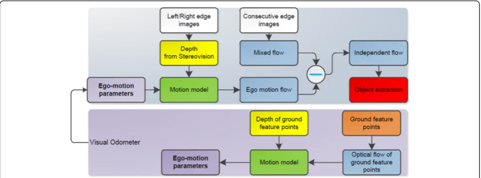
The difficulty of motion detection from a moving cam-era/vehicle is that the background is also moving and its motion is mixed with target motion. Therefore, the key of motion detection in dynamic scenes is to distinguish the background motion from the target motion. The underlying idea of our approach is to subtract the mo-tion of the camera (ego-momo-tion) from the calculated (mixed) optical flow, that is, a moving target can be detected from the difference between the mixed optical flow and the ego-motion optical flow. Figure 1 gives an overview of the approach.
The mixed flow of the scene is caused by both camera motion and target motion and is obtained from correspondence matching between consecutive images. The ego-motion flow is caused only by cam-era motion and calculated from a mathematical model
derived from Waxman and Duncan’s theoretical
ana-lysis [22], which indicates the relation between optical flow, depth map, and camera ego-motion parameters. To calculate the ego-motion flow, we need first know the ego-motion parameters of six degree of freedom.
A visual odometer has been implemented for this purpose, in which six motion parameters are esti-mated by solving a set of equations fitted with a fixed number of feature points using the linear least square method. The feature points are selected as corner points lying on the road surface and determined by using height constraint and Harris corner detection algorithm [23]. Within the two stages, the depth of the image points is provided by the stereovision dis-parity map. The difference between the mixed flow and the ego-motion flow yields an independent flow which is purely caused by the target motion. The moving target is extracted according to the continuity of the similar independent flow.
To reduce the computational workload and consider-ing that object contour is the most effective cue for object segmentation, all calculations are edge-indexed, i.e., we only conduct calculations on edge points for ste-reo matching, the mixed flow, and the ego-motion flow calculations. This tactic greatly increases the real-time performance and has no impact on object detection performance.
2.2 The mixed flow
Many methods have been developed to calculate dense optic flow from image sequences [24]. Basically, these ap-proaches can be split into two categories: spatiotemporal gradient-based and correspondence matching techniques. The spatiotemporal gradient-based techniques calculate optic flow based on assumptions including globe smooth-ness or direction smoothsmooth-ness. Our experiences show that these methods take huge computation cost and are diffi-cult to obtain accurate optical flow in complex traffic sce-narios. The correspondence matching-based techniques detect optic flow by searching for correspondence points between consecutive images, therefore are more suitable
for dynamic traffic scene images. In this work, we implement an edge-indexed correspondence matching algorithm based on greyscale similarity to calculate the mixed optical flow. The details of the algorithm can be found in our previous work [25]. A summary is as follows:
Step 1. Generate edge image using Canny operator and use the edge points as seed points to find the correspondence points in next frame.
Step 2. Define the searching range as a square area centered at the seed point and define a rectangular matching window.
Step 3. Use the normalized cross correlation coefficients as a measure of greyscale similarity of two matching windows. The correspondence points are regarded as those with the maximum cross correlation coefficient that must be greater than a predefined threshold.
Step 4. Achieve the sub-pixel estimation of the calculated optical flow along the vertical and horizontal directions by introducing a quadratic interpolation. This is to improve the optical flow resolution so that a higher optical flow accuracy can be achieved.
2.3 3-dimensional motion and ego-motion flow
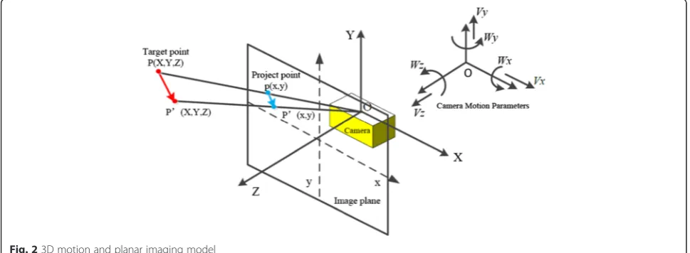
Ego-motion flow is the optical flow evoked by the mov-ing camera/vehicle, representmov-ing the effect of the camera
motion. The camera’s 3-dimensional motion and planer
imaging model is represented in Fig. 2. The origin of the world coordinate system (X,Y,Z) is located at the center of image coordinates (x, y), and the Z-axis is directed along optical axis of the camera. The translational vel-ocity of the camera is V ¼ Vx;Vy;Vz and camera motion is as below [22]:
dP
dt ¼−ðV þW PÞ ð1Þ
The cost product of the point P(X,Y,Z) and camera’s rotational velocity vector can be represented as
The 3-dimensional velocity dX
dt point can be obtained as below:
dX=dt¼− VxþWyZ−WzY
For an ideal pinhole camera model, the image point
p(x y) of the world point P(X, Y, Z) projected in the image plane can be expressed as
x¼fX
Z; y¼f Y
Z ð5Þ
where f denotes the focal length of the stereo camera. The optical flow (u, v) of P(X,Y,Z) can be obtained by
estimating the derivatives alongX-axis and Y-axis in 2D
Integrating Eqs. (4) to (6) yields the following:
u
Equation (7) indicates the relationship between the ego-motion flow, the depth and the six parameters of the camera motion. It is evident that the ego-motion flow can be calculated from Eq. (7) if the depth and the six motion parameters are known. The depth can be ob-tained from stereovision as reported in our previous work [26]. Two methods can be used to obtain the mo-tion parameters: one is to use an in-vehicle INS or gyro-scope to measure them; the other is to use a visual odometer. However, subject to problems like navigation loss, wheel slip, INS saturation, and calibration errors between the IMU and the cameras, in-vehicle INS may cause inaccurate motion estimation in some cases. Thus, it is ideal to estimate the camera motion directly from the imagery. Ultimately, it could be fused with other state sensors to produce a more accurate and reliable joint estimate of cameral/vehicle motion.
2.4 Visual odometry
It can be known from Eq. (7) that if the ego-motion flow and the depth of six or more points in the scene are known, we can set up a set of equations with six unknown variables, i.e., six camera motion parameters and estimate these variables by solving the equations set using the least square fitting method. The points used for the least square fitting must be assured with accurate optical flow calculation and must not be any moving points.
In this work, the corner points lying on the road sur-face are selected for this purpose since the ground points are static and the corner points are of good stabil-ity and inflexibilstabil-ity to light intensstabil-ity, therefore possessing relatively accurate optical flow.
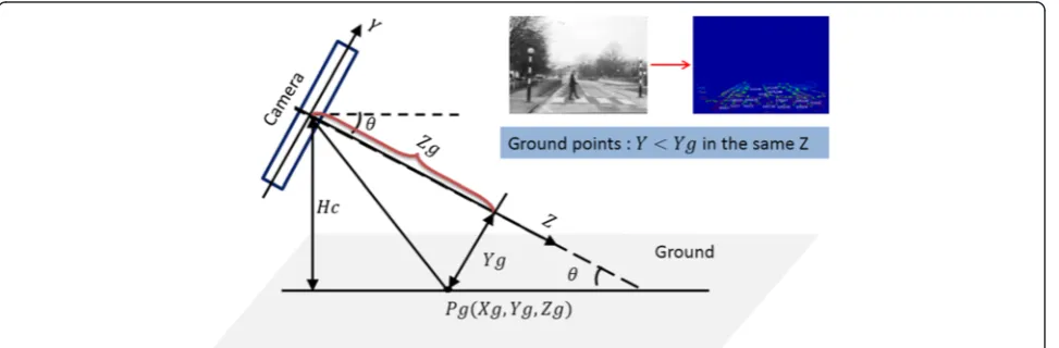
2.4.1 Extraction of ground corner points using stereovision and Harris method
Ground points can be determined from the height infor-mation that can be obtained from the stereovision as
re-ported in our previous work [26]. The height Yg of the
ground points, namely their Y-axis coordinate, depends
on the camera installation height Hc, the tilt angle to-wards the road plane θ, and distanceZg, as indicated in Eq. (8) and Fig. 3. Those points with Y-axis coordinate less thanYgare regarded as ground points.
Yg ¼ Zg sinθ−Hc
=cosθ ð8Þ
A corner is defined as a point for which there are two dominant and different edge directions in a local neigh-borhood of the point. Harris corner points are detected by considering the differential of the corner score with respect to direction [23]. The corner score is referred as autocorrelation. Assuming that a pixel I(X,Y) moves in any directions by small displacements (∇x,∇y), the auto-correlation function is defined as below:
C∇x;∇y ¼
where φ(x,y) is Gaussian weighting function used here to reduce the impact of noise; W(x,y) denotes window blocks centered at the point;Ixis the gradient inx direc-tion; andIyis the gradient inydirection. The Sobel con-volution kernel ωx and its transposed form ωy are used to obtain Ix= I(X,Y) ⊗ωx , and Iy= I(X,Y) ⊗ωy.
M(x,y) is called the autocorrelation matrix and
M xð ; yÞ ¼φðx;yÞ
The corner response function (CRF) can be calculated as.
CRF¼ detð ÞM −α⋅ðtraceMÞ2 ð11Þ
where det(M) =λ1×λ2 and traceM =λ1+λ2, λ1 and λ2 denote the eigenvalues of the matrixM, we set α= 0.04. The point with CRF bigger than a certain threshold is regarded as a corner point.
2.4.2 Ego-motion parameter estimation using the linear square algorithm
The objective function is defined as the Euclidean dis-tance between the estimated optical flow ð^u;^vÞ and the
The true optical flow (u,v) is calculated from the method introduced in Section 2.2. The estimated optical flow ðu^;^vÞ ¼ AðV;WÞT is obtained from Eq. (7). The minimum value of the object function is found by set-ting the gradient to zero and the optimal parameter values are
V;W
ð Þ ¼ATA−1ATðu;vÞ ð13Þ
where A denotes the coefficient matrix made up with the focal lengthfof the stereo camera, the depthZ, and the image coordinates as shown in Eq. (7).
2.5 Independent flow and target segmentation
The difference between the mixed flow and the ego-motion flow yields the independent flow which attri-butes purely to moving targets. This operation ideally cancels out the effects of inter-fame changes caused by vehicle motion and involves a 2D vector difference:
ur vr
½ ¼½um vm−½ue ve ð14Þ
where [ur vr] denotes the independent flow in the hori-zontal and vertical directions, [um vm] the mixed flow, and [ue ve] the ego-motion flow. The synthetic of the two components of the independent flow is calculated as
s¼pffiffiffiffiffiffiffiffiffiffiffiffiffiffiffiffiu2þv2 . Target segmentation is based on the
syn-thetic independent flow.
In theory, the independent flow of the background should be zero. However, the background has some re-sidual independent flow due to calculation errors. The key to distinguish a moving object from the background is to determine a threshold of the independent flow. In this work, we adopt the OTSU algorithm to determine a self-adapting threshold. The algorithm can be described as follows:
1. For a thresholdt,smin<t<smax, define the variance
ε(t) between the moving target’s independent flow and the background’s independent flow as
εð Þ ¼t Poðso−tÞ2þPgsg−t2 ð15Þ
wheresodenotes the mean of the independent flows of the
moving points, so¼
X
sipi
po ðsi>t; i¼1; 2; 3…Þ, sg denotes the mean of the independent flows of the
back-ground points,sg ¼
X
sipi
pg ðsi<t; i¼1; 2; 3…Þ;po denotes the proportion of the points withs>t,pg the pro-portion of the points withs<t, andpithe proportion of the points withs<si.
2. Search for thetfromsmintosmaxto makeε(t)
maximum and use it as the threshold to segment the moving objects from the background. This process endures a maximum between-class distance.
3 Experiments and results
A VIDERE stereo rig with strict calibration is used to capture images in this work. The two cameras have the image resolution of 640 × 480 pixels, the pixel size of
15μm, and the baseline of 218.95 mm. The focal length
is 16.63 mm. The detection ranges from −8 to 8 m in
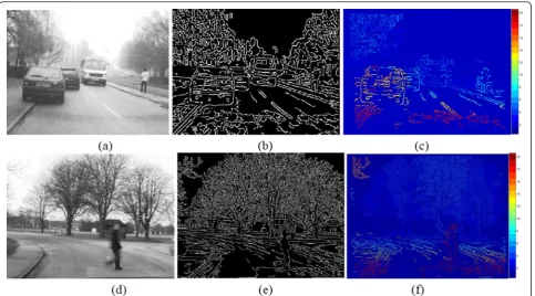
lateral and from 4 to 50 m in distance. Figure 4a, d shows the left images of two typical traffic scenarios. The first scenario involves a pedestrian, an oncoming
coach, and some static obstacles like parked cars and trees, where the equipped vehicle moves in longitudinal direction. In the second scenario, the vehicle is turning in a bend. It helps to evaluate our algorithm when the vehicle undergoes more complex movement.
3.1 Disparity of stereovision
Figure 4b, e shows the edge maps obtained from a Canny detector. The edge points in the left image are Fig. 4Traffic scenarios and disparity images.aLeft imageat frame 72 of scenario 1.bEdge image of scenario 1.cDisparity map of scenario 1.d
Left imageat frame 72 of scenario 2.eEdge image of scenario 2.fDisparity map of scenario 2
used as seed points to search for the correspondence points in the right image by using greyscale similarity as the measure. The resulting disparity maps are displayed in Fig. 4c, f. A color scheme is used to visualize the dis-parity. The depth information of the image points can be derived from the disparity map. It should be noted that some points like the trees out of the detection range are not presented in the disparity maps. It is worthy to be noted that contour occluding could be generated due to the different viewpoints of the two cameras and may bring troubles for stereo correspondence match-ing especially for a short distance with a wider base-line. In our application, we use a relatively short stereo baseline of 218.95 mm, and the detection range is 4 to 50 m. The occluding effect is not significant. In addition, stereo matching depends on the selection of matching windows and setting of threshold of cor-relation coefficient. The detailed edge-indexed stereo matching procedure can be found in our previous work [26]. All experiments show that the edge-indexed stereo matching can successfully generate an edge-indexed disparity map.
3.2 Mixed flow results
Figure 5 shows the mixed flow obtained using the edge-indexed correspondence matching algorithm described in Section 2.2. It can be noted that even for static objects like parked cars, trees, and ground points, there is obvi-ous motion, which is caused by camera/vehicle’s motion. The motion of the pedestrian and the oncoming coach is significantly different from its surroundings due to its own motion. The mixed motion shown in Fig. 5a, b re-flects actual movement of the points and will be used for subtraction of motion flows in late stage.
3.3 Visual odometer results
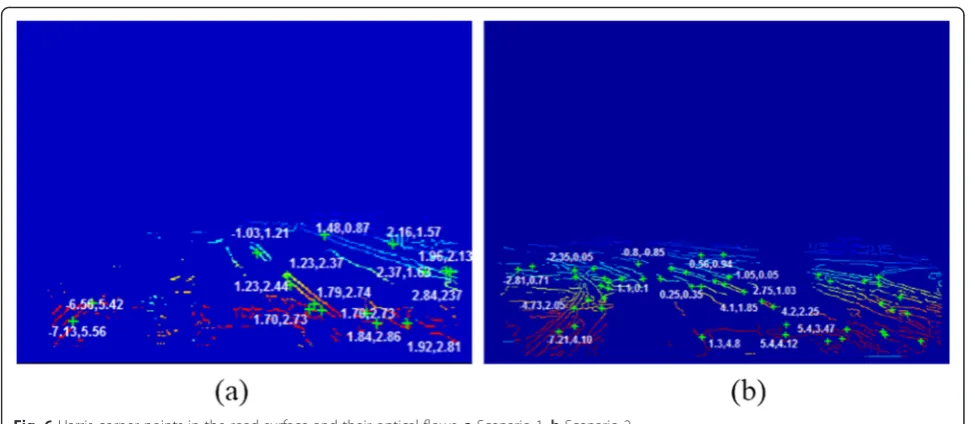
The edge points in the ground surfaces are successfully extracted, as shown in Fig. 6a (scenario 1) and 6b (sce-nario 2). The Harris corner points are detected and marked with “+”in the figures. For each case, 15 Harris Corner points with higher CRF scores are selected to set up a set of equations for estimating the six ego-motion parameters using the least square fitting method. The re-sults are presented in Table 1. It can be found that for both scenarios,Vzare significant andVy,Wx,Wy, andWz are tiny. This is reasonable since the vehicle was moving with a certain speed in a relatively flat road. For scenario 2,Vxis also significant because the vehicle was left
turn-ing in a bend. For scenario 1,Vx is equal to 0.17 m/
frame, indicating that the vehicle was not strictly moving in longitudinal direction and had a small lateral moving at the moment.
During the video acquisition, a spatial NAV 982 Iner-tial Navigation System was fitted in the car to measure the ego-motion parameters. Although the INS may lose detection in some cases, the comparison between the effective data of two systems shows that the difference of the results is within 4 %, indicating that our visual odometer is reasonably accurate.
3.4 Ego-motion flow results
The ego-motion flow calculated from Eq. (7) by using above estimated ego-motion parameters is shown in Fig. 6Harris corner points in the road surface and their optical flows.aScenario 1.bScenario 2
Table 1Results of ego-motion estimation
Ego-motion parameters Scenario 1 Scenario 2
Vx Vy Vz ðm=frameÞ −0.22−0.04 227.04 48.61−0.03 214.25
Fig. 7. The ego-motion shown in Fig. 7a, b will be used for subtraction of motion flows in late stage.
3.5 Independent flow and motion extraction
The subtraction of Fig. 7a from Fig. 5a is shown in Fig. 8a, while the subtraction of Fig. 7b from Fig. 5b is shown in Fig. 8b. The subtraction yields the independent flow which is purely caused by the target motion. It can be seen that the most of the background have been can-celed out and the moving objects are significantly
highlighted using the method described in Section 2.5. Furthermore, the pedestrian can be framed according to the continuity of the similar independent flow, as shown in Fig. 8c, d.
3.6 Evaluation of the system
Experiments have also been conducted on the public image database KITTI (Karlsruhe Institute Technology and Toyota Technological Institute) [27]. Figure 9 shows the process of motion detection for one of the Fig. 7Ego-motion flow calculated from Eq. (7) by using the estimated ego-motion parameters. aThe ego-motion flow of scenario 1.
bThe ego-motion flow of scenario 2
scenarios containing multiple moving obstacles. A total of 5000 frames of various scenarios with hand-labeled moving objects including pedestrians and cars have been tested using our approach. In general,
Recall and Precision are usually used to assess the ac-curacy of object detection.
Recallis defined as follows:
Recall¼ tp
tpþf n ð16Þ
where tp is the total number of true-positively detected objects, fn is the total number of false-negatively de-tected objects, and (tp + fn) indicates the total number of objects in the ground truth. Precision is defined as follows:
Precision¼ tp
tpþf p ð17Þ
where fp is the total number of false-positively detected
objects, and (tp + fp) indicates the total number of the detected objects.
Table 2 lists the performance of our method in terms of detection of pedestrians and cars.
The system is implemented with C++ language in an industrial computer equipped with a 2.40-GHz Intel Dual Core i5 processor and 4 GB of RAM. In general,
we can achieve a processing rate of 10–15 frames per
second (FPS), depending on complexity of the images. This processing rate includes the stereo pre-processing time. Ideally, it should work at least 25 FPS for a real-time system. But we believe that it will not be a problem to achieve this by using a bespoke image processing hardware in future.
Fig. 9Detection results for one of KITTI scenarios.aFrame 905.bEdge image.cDisparity image.dFeature points in ground plane.eMixed flow.
fEgo-motion flow.gIndependent flow.hExtraction of the moving objects
Table 2Accuracy rate of our method
Object type under detection Precision Recall
Pedestrian 94.0 % 92.2 %
3.7 Comparison with other methods
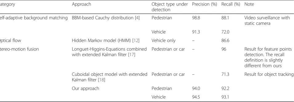
Table 3 lists the comparison with the some other work reported for moving object detection including applica-tions in video surveillance [4]. It is a hard task to make a uniform comparison with other approaches for two rea-sons: (1) Evaluation metric used can be different; (2) Many research work do not give statistical accuracy rate. The work most related to our approach can be found in
[14–19], which use stereo-motion fusion. However,
there are no reports on detection rate or accuracy
rate in [14–16, 19]. In [17], authors only give the
accuracy for feature point detection rather than ac-curacy for object detection. Moreover, the acac-curacy definition is slightly different from ours. In [18], authors only provide result for object tracking.
4 Conclusions
This paper presents a novel motion detection approach using a stereovision sensor for in-vehicle environment sensing system. The relationship between optical flow, stereo depth, and camera ego-motion parameters has been established. Accordingly, a visual odometer has been implemented for estimation of six ego-motion pa-rameters by solving a set of equations fitted with a num-ber of feature points using the linear least square method. The feature points are selected as corner points lying on the road surface and determined by using height constraint and Harris corner detection algorithm. The ego-motion flow evoked by the moving camera/ve-hicle is calculated from the relational model by using the estimated ego-motion parameters. The mixed flow caused by both camera motion and target motion is obtained from the correspondence matching between consecutive images. The difference between the mixed flow and the ego-motion flow yields the independent flow which attributes purely to the target motion. The moving targets are extracted according to the continuity of the similar independent flow. The approach presented
here was tested on substantial complex urban traffic vid-eos. The experimental results demonstrate that the ap-proach can detect moving objects with a correction rate of 93 %. The accuracy of ego-motion estimation is within 4 %, comparing to an in-vehicle INS sensor. The processing rate reaches 10–15 FPS on an industrial com-puter equipped with a 2.40-GHz Intel Dual Core i5 processor and 4 GB of RAM.
Competing interests
The authors declare that they have no competing interests.
Acknowledgements
This work was sponsored by Specialized Research Fund for the Doctoral Program of Higher Education (Project No. 20133120110006), the National Natural Science Foundation of China (Project No. 61374197), and the Science and Technology Commission of Shanghai Municipality (Project No. 13510502600).
Received: 7 September 2015 Accepted: 12 April 2016
References
1. JE Ha, WH Lee, Foreground objects detection using multiple difference images. Opt. Eng4, 047–201 (2010)
2. M.C. arco, F. Michela, B. Domenico, M. Vittorio, Background subtraction for automated multisensor surveillance: a comprehensive review. EURASIP. J. Adv. Signal. Process. 2010, 343057. doi:10.1155/2010/343057
3. L Wei, H Yu, H Yuan, H Zhao, X Xu, Effective background modelling and subtraction approach for moving object detection. IET Computer Vision 9(1), 13–24 (2015)
4. FC Cheng, SJ Ruan, Accurate motion detection using a self-adaptive background matching framework. IEEE Trans. Intell. Transp. Sys13(2), 671–679 (2012)
5. A. Broggi, A. Cappalunga, S. Cattani, P. Zani. In Proceedings of IEEE Intell. Veh. Symp. Lateral vehicles detection using monocular high resolution cameras on TerraMax, (2008), pp. 1143–1148
6. Y Zhu, D Comaniciu, M Pellkofer, T Koehler, Reliable detection of overtaking vehicles using robust information fusion. IEEE Trans. Intell. Transp. Syst7(4), 401–414 (2006)
7. L. Kui, D. Qian, Y. He, M. Ben. Optical flow and principal component analysis-based motion detection in outdoor videos. EURASIP. J.Adv. Signal Process. 2010, 680623. doi:10.1155/2010/680623
8. L. Yang, X.F. Li, J. Limin, In Proceedings of the 11th World Congress on intelligent control and automation (WCICA). Abnormal crowd behavior detection based on optical flow and dynamic threshold (2014), pp. 2902-2906
Table 3Comparison with other research work
Category Approach Object type under
detection
Precision (%) Recall (%) Note
Self-adaptive background matching BBM-based Cauchy distribution [4] Pedestrian 98.8 88.1 Video surveillance with static camera
Vehicle 91.3 72.0
Optical flow Hidden Markov model (HMM) [12] Vehicle only – 86.6
Stereo-motion fusion Longuet-Higgins-Equations combined with extended Kalman filter [17]
Pedestrian or car – 96 Result for feature points detection. The recall definition is slightly different from ours
Cuboidal object model with extended Kalman filter [18]
Pedestrian or car – 71.3 Result for object tracking
Our approach Pedestrian 94.0 92.2
9. E. Martinez, M. Diaz, J. Melenchon, J. Montero, I. Iriondo, J. Socoro, In Proc. IEEE Intell. Veh. Symp.. Driving assistance system based on the detection of head-on collisions (2008); pp. 913–918
10. J Diaz Alonso, E Ros Vidal, A Rotter, M Muhlenberg, Lane-change decision aid system based on motion-driven vehicle tracking. IEEE Trans. Veh. Technol57, 2736–2746 (2008)
11. I. Sato, C. Yamano, H. Yanagawa, In Proc. IEEE IV. Crossing obstacle detection with a vehicle-mounted camera (2011), pp. 60–65
12. H Jazayeri, J Cai, Y Zheng, M Tuceryan, Vehicle detection and tracking in car video based on motion model. IEEE Trans. Intell. Transp. Syst.12(2), 583–595 (2011)
13. H. Geiger, B. Kitt, In Proc. IEEE Intell. Veh. Symp. Object flow: a descriptor for classifying traffic motion (San Diego, USA, 2010), pp. 287–293
14. D. Pantilie, S. Nedevschi, In Proc. IEEE Conference on Intelligent Transportation Systems. Real-time obstacle detection in complex scenarios using dense stereo vision and optical flow (Funchal, 2010), pp. 439–444 15. U Franke, S Heinrich, Fast obstacle detection for urban traffic situations. IEEE
Trans. Intell. Transp. Syst3(3), 173–181 (2002)
16. C. Rabe, U. Franke, S Gehrig, In Proceedings of IEEE Intelligent Vehicles Symposium. Fast detection of moving objects in complex scenarios (2007), pp. 398–403
17. B. Kitt, B. Ranft, H. Lategahn, In Proc. 13th Int. IEEE Conf. on ITSC. Detection and tracking of independently moving objects in urban environments (2010), pp. 1396–1401
18. S. Bota, S. Nedevschi, In Proc. 14th Int. IEEE Conf. ITSC, Tracking multiple objects in urban traffic environments using dense stereo and optical flow (2011), pp. 791–796
19. P. Lenz, J. Ziegler, A. Geiger, In Proc. IEEE Intell. Veh. Symp.. Roser M. Sparse scene flow segmentation for moving object detection in urban environments (Baden-Baden, Germany, 2011), pp. 926–932
20. T. Yamaguchi, H. Kato, Y. Ninomiya, In Proc. IEEE Intell. Veh. Symp.. Moving obstacle detection using monocular vision (2006), pp. 288–293 21. A. Talukder, L. Matthies, In Proc. IEEE Int. Conf. Intelligent Robots and
Systems. Real-time detection of moving vehicles using dense stereo objects from moving and optical flow (2004), pp. 3718-3725
22. AM Waxman, JH Duncan, Binocular image flows: steps towards stereo-motion fusion. IEEE Trans Pattern Anal Mach Intell8, 715–729 (1986) 23. C. Harris, M.A. Stephens, In Proceedings of the 4th Alvey Vision Conference.
Combined corner and edge detector, (1988), pp. 147–151
24. B McCane, K Novins, D Crannitch, B Galvin, On benchmarking optical flow. Comput Vis Image Underst84, 126–143 (2001)
25. Y. Huang, K. Young. Binocular image sequence analysis: integration of stereo disparity and optic flow for improved obstacle detection and tracking. EURASIP. J Adv. Signal. Process. 2008, 843232. doi:10.1155/2008/ 843232
26. Y Huang, S Fu, C Thompson, Stereovision-based object segmentation for automotive applications. EURASIP J Appl Signal Process14, 2322–2329 (2005)
27. KITTI Vision, Available online: http://www.cvlibs.net/datasets/kitti/, Accessed 18 Jul 2015.
Submit your manuscript to a
journal and benefi t from:
7 Convenient online submission 7 Rigorous peer review
7 Immediate publication on acceptance 7 Open access: articles freely available online 7 High visibility within the fi eld
7 Retaining the copyright to your article