An Efficient Ripple Carry Adder Based Low
Complexity Turbo Decoder
Chandrapriya.G1, Karthigailakshmi.S2
1
P.G.Scholar, Francis Xavier Engineering College, Tirunelveli,India.Email:[email protected]
2
Associate Professor /ECE, Francis Xavier Engineering College, Tirunelveli,India.
Abstract— The energy efficient ripple carry adder based turbo decoder is required in CDMA2000, WCDMA (UMTS) and HSDPA receivers to decode the data packets between the mobile station and network provided by 4G standard. The high throughput cellular standards 3GPP/4G require an energy efficient decoder architecture. An efficient VLSI architecture for turbo decoder by utilizing state metric calculator is presented here. In decoding, the state metric calculator is inserted to perform state metric calculations. This energy efficient turbo decoder comprises level limiter, error generator, SOVA decoder, state metric calculator, interleaver and corresponding deinterleaver. The ripple carry adder based turbo decoder achieved a low energy consumption of 0.4w.
Keywords—interleaver, limiter, logarithmic likelihood ratio mobile communications, turbo decoder,
I.INTRODUCTION
Wireless sensor networks (WSNs) are an important technology for large scale monitoring, providing sensor measurements. The sensors are operated for extended periods of time relying on batteries that are small, lightweight and inexpensive. In 4G standards, the aim of high data rate such as 100Mb/s places a considerable strain on total power consumption of decoder [1].In Latest wireless communication applications, Signal processing and digital electronics systems come with embedded small batteries that are capable to process and communicate with each other. The issue of minimizing the energy consumption is critical and need to minimize energy consumption at the levels of encoding and decoding levels.
For this reason, the energy efficient turbo decoders are recently considered for energy constrained Wireless sensor network scenarios to reduce overall decoder’s energy consumption .In 1974, Bahl, Cocke, Jelinek and Raviv found the Maximum a Posteriori (MAP) algorithm known as BCJR algorithm shows best error rate performance [1]. The Map algorithm is computationally complex and sensitive to SNR mismatch and inaccurate estimation of the noise variance.
The logarithmic version of Map algorithm was introduced. The Log Map algorithm is less complex but provides poor decoding performance. Turbo codes are invented in 1993, has attracted excellent decoding performance in wireless and satellite communication applications [2], [6]. The turbo code based Max log map BCJR algorithm was introduced. The Max log map BCJR algorithm achieves the high throughput of 100Mb/s with 0.5dB coding gain degradation. Previous method of Conventional turbo decoder architecture
use sliding window technique. The three recursion techniques are employed. There are forward recursion, backward recursion and prebackward recursions. In the Conventional turbo decoder architecture ,the forward recursion values,backward recursion values and prebackward recursion values using dedicated hardware units of forward recursion calculator, backward recursion calculator and prebackward recursion calculator. This architecture provides excellent decoding performance with cost of hardware complexity and high power consumption. This motivates the energy efficient ripple carry adder based turbo decoder. To facilitate iterative decoding, turbo decoders require Soft output component algorithm among BCJR algorithm is widely accepted for excellent decoding performance [11]. The turbo decoder consists of Soft output component decoders and operates by iterative decoding. The LLR computation has lower bit error rate complexity .To find the Maximum likelihood logarithmic ratio, trellis encoder and trellis decoder and soft output component decoders are required. This architecture produces 71% energy consumption reduction of decoder compared to Conventional turbo decoder architecture.
The reminder of this paper is organized as follows: section 2 explains the Conventional turbo decoder. The Decoder involves the techniques of forward recursion, backward recursion and prebackward recursion to generate the error corrected decoded data. Section 3 presents the proposed architecture of energy efficient ripple carry adder based turbo decoder. Section 4 discuss the simulation results of Level limiter, Error generator unit, Soft output upper component decoder, State metric calculator , Soft output Lower component decoder ,trellis encoder and trellis decoder.
II. CONVENTIONAL TURBO DECODER ARCHITECTURE
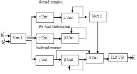
Figure 1: Conventional turbo decoder architecture
The Conventional turbo decoder architecture consists of dedicated hardware units of alpha unit, beta unit and gamma unit to calculate the forward recursion values, backward recursion values and prebackward recursion values. But it involves more iteration. The conventional turbo decoder architecture consumes high energy consumption. The forward and backward recursion values are generated by alpha and beta units. Finally, the value of LLR is generated This motivates the new generation of energy efficient turbo decoder architecture. This architecture decompose entire BCJR algorithm into most basic operations of additions, subtractions and Max* operations. The entire algorithm performed by one smart state metric calculator unit. This architecture does not involve many multiplications. Hence, hardware complexity reduced and energy consumption is also reduced. So, Energy wastage is avoided, the critical path is short and equally lengthened, eliminating the additional hardware to control the architecture units to calculate path metric values. So the critical path is reduced. This avoids the energy wastage. This architecture produces the 71% of energy consumption reduction of transmitting power than the previous conventional turbo decoder architectures. So the Modified energy efficient turbo decoder architecture is widely used in wireless senor network communication applications.
III.PROPOSED SYSTEM-ARCHITECTURE
A.Energy efficient ripple carry adder based turbo decoder architecture
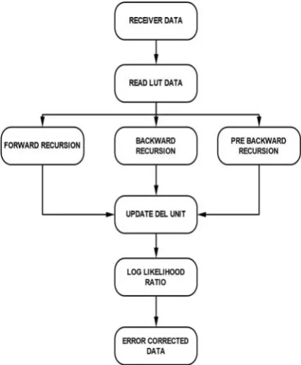
Figure 2: Flow diagram of turbo decoder
The encoded data transmitted through the Additive white Gaussian noise channel, the data corrupted by the noise while it is received at the receiver side. At the receiver side, the Energy efficient ripple carry adder based turbo decoder architecture is placed. The energy efficient ripple carry adder based turbo decoder architecture consists of two soft
output component upper and lower decoders. The decoder consists of state metric calculator. The state metric calculator consists of trellis encoder and trellis decoder. The state metric calculator receives the data from lookup table and calculates the state metric weight.
The lookup table used to store the intermediate calculation values. The results used in soft output lower component decoder process the Logarithmic likelihood ratio. Finally the error corrected decoded data is generated.
The Coder unit takes input data a, b, q1, q2 and q3 as input and produces the y, w encoded output signals. The encoder outputs range limited to binary value of 0111.Beyond the value 0111 such as 1100 means, level limiter reduces it into upper level limit of 0111 range otherwise it process the input(Below 0111) as it is. The limiter output of encoded data is transmitted to the receiver side decoder. The level limiter output is fed to the input of error generator unit.The error generator unit punctures the received original data and generates the punctured data.
Figure: 3 Iterative turbo decoder setup
“I “represent Interleaver.
The Decoder setup consists of Soft output upper Decoder component, Soft output Lower decoder component, State metric calculator, trellis encoder and trellis decoder. The State metric calculator receives the input signals of clock signal, reset signal, a-Noise signal, b-Noise signal, y-Noise signal, w-Noise signal and extrinsic information to compute the weight. To calculate the state metric value of p-q difference, the distance information is needed. For that, the part distance is computed by add all the values and take the opposite of part distance value. Then the part distance information and extrinsic information are added and generate distance value. To compute the accumulated distance value, 32 bit adder is used. For that the adder receives the operand1 and second operand. The adder add two operands and given to the reduction unit. The reduction unit reduces the output into reduced array of accumulated distances of 32 bit. The minimum distance is selected by using multiplexer unit. The array of accumulated distances of 32 bit is fed into in8x4 multiplexer unit. The multiplexer
output fed into 4:1Mux. The 4:1 multiplexer inputs are assigned as p operand and Output of 4:1Mux assigned as q operand of subtractor unit. The subtractor unit found the P-Q difference value.
Trellis Encoder defines the states and found the pathid and then exor the states. Trellis Decoder reverse process of trellis encoder. It uses stored buffered state metric values and compute LLR.
B.Computational steps of Energy Efficient ripple carry adder Based Turbo Decoder:
1.The input signals of encoded outputs are a-Noise signal, b-Noise signal, y-Noise signal, w-Noise signal and extrinsic information are applied to the first soft output upper component decoder.
2.The input signals of a-Noise, b-Noise, y-Noise, w-Noise signals, extrinsic information (Zin) are taken by State metric calculator to compute the p-q difference. Using this value, the upper decoder generates decoder outputs of zout, adecoderinternal output and bdecoderinternal outputs.
3.The output of upper component decoder is permuted by permutation unit.
4.The permuted information is interleaved by interleaver unit to generate the zoutperm.
5.The interleaved values are fed to the delayer unit to generate the internal delayed values a, b, y, w.
6.The systematic information a, b are permuted to generate the abpermutation values.
7.The second lower soft output component decoder receives the inputs from upper soft output component decoder outputs.
8.The second soft output lower component decoder process these signals and generates the zout2, a-decoder and b-decoder outputs.
9.Finally the output of second soft output lower component decoder is deinterleaved to produce the turbo decoder outputs a-decoder and b-decoder.
IV RESULTS
A. Input signals y, w generated
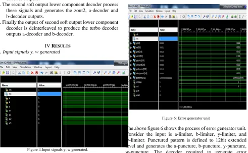
Figure 4.Input signals y, w generated.
Figure 4 shows the input signals of coder generated using a, b signals. Consider a, b, q1, q2, q3 as an input. Exor operation is performed between a, b, q1, q2, q3 to generate the y signal. The Exor operation is performed between a, b, q1, q3 to generate the w signal.
B. Level limiter
Figure 5:Limiter output
The above figure 5 shows the process of level limiter.Consider the input is anoise= 0010, bNoise = 0011, yNoise = 0001, wNoise = 1000.The level limiter outputs are alim=0010 ,bNoise = 0011, yNoise = 0001, wNoise = 0111.
C.Error generator unit
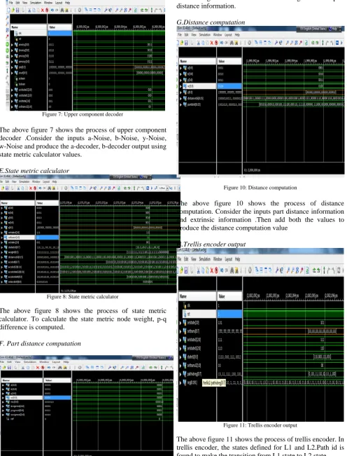
Figure 6: Error generator unit
The above figure 6 shows the process of error generator unit. Consider the input is a-limiter, b-limiter, y-limiter, and w-limiter. Punctured pattern is defined to 12bit extended level and generates the a-puncture, b-puncture, y-puncture, w-puncture. The decoder required to generate error corrected data with received punctured data.
D.Upper component decoder
Figure 7: Upper component decoder
The above figure 7 shows the process of upper component decoder .Consider the inputs a-Noise, b-Noise, y-Noise, w-Noise and produce the a-decoder, b-decoder output using state metric calculator values.
E.State metric calculator
Figure 8: State metric calculator
The above figure 8 shows the process of state metric calculator. To calculate the state metric node weight, p-q difference is computed.
F. Part distance computation
Figure 9: Part distance computation
Figure 9 shows the part distance computation Consider the inputs a-Noise signal, b-Noise signal, y-Noise signal, w-Noise signal and then add the values to generate the part distance information.
G.Distance computation
Figure 10: Distance computation
The above figure 10 shows the process of distance computation. Consider the inputs part distance information and extrinsic information .Then add both the values to produce the distance computation value
H.Trellis encoder output
Figure 11: Trellis encoder output
The above figure 11 shows the process of trellis encoder. In trellis encoder, the states defined for L1 and L2.Path id is found to make the transition from L1 state to L2 state .
I. Trellis decoder
Figure 12: Trellis decoder.
The above figure 12 shows the process of trellis decoder output. Consider the input data state metric values. The lower component decoder process the LLR and generates the decoded data output.
J.Turbo Decoder output
Figure 13: Turbo decoder output
The above figure 13 shows the process of turbo decoder output. Consider the inputs a-Noise, b-Noise, y-Noise and w-Noise. Second component decoders process these signals and produce the a-decoder and b-decoder output signals.
K. Energy estimation
Figure 14: Energy estimation
Figure 14 shows the energy consumption analysis of turbo decoder. This energy efficient ripple carry adder based turbo decoder architecture consumes less power consumption of 0.4w than conventional turbo decoder architecture. This energy efficient ripple carry adder based
turbo decoder provides 71% energy consumption reduction of turbo decoder.
L. Path delay analysis
Figure 15: Path delay analysis
The above figure of 15 shows the path delay analysis. The path delay is found to be 41.971ns only. So the throughput is high.
M. Comparison between Conventional turbo decoder architecture and Energy efficient ripple carry adder based turbo decoder architecture.
Table 1: Comparison table
V. CONCLUSION
In conclusion, this study presented the design of Energy efficient ripple carry adder based turbo decoder architecture and energy consumption analysis. To increase the energy efficiency, the energy efficient ripple carry adder based turbo decoder architecture is designed. The State metric calculator is used to calculate the state metric values. Interleaver address generation is used in this project, so that large multiply modulo stages can be avoided. For turbo codes and serial concatenated codes employing iterative soft output decoders and state metric calculator units achieves a shorter critical path length .The path delay was found to be 41.971ns. The energy consumption is 0.4w. We have achieved 71% energy consumption reduction in energy efficient ripple carry adder based turbo decoder compared to the conventional turbo decoder architecture.
REFERENCES
[1] C. Benkeser, A. Burg, T. Cupaiuolo, and Q. Huang, “Design and optimization of an HSDPA turbo decoder ASIC,” IEEE J. Solid-State Circuits,vol. 44, no. 1, pp. 98–106, Jan. 2009.
[2] Y. Zhang and K. K. Parhi, “High-throughput radix-4 log MAP turbo decoder architecture,” in Proc. Asilomar Conf. Signals, Syst., Computer, 2006, pp. 1711–1715.
[3] Christoph Studer, Student Member, IEEE, Christian Benkeser,
Member, IEEE, Sandro Belfanti, and Quiting Huang, Fellow, IEEE “Design and Implementation of a Parallel Turbo-Decoder ASIC for 3GPP-LTE” , IEEE J. Solid-State Circuits, vol. 46, pp. 8–17, 2011. [4] Mark A. Bickerstaff, Member, IEEE, David Garrett, Member, IEEE,
Thomas “A Unified Turbo/Viterbi Channel Decoder for 3GPP Mobile Wireless in 0.18-_m CMOS”IEEE J. Solid-State Circuits, vol. 37, no. 11, pp. 1555–1564, Nov. 2002.
[5] Fan-Min Li, Cheng-Hung Lin, Student Member, IEEE, and An-Yeu
(Andy) Wu, IEEE Member “Unified convolutional/turbo decoder
design using tile-based timing analysis of VA/MAP kernel,”,IEEE Trans. Very Large Scale Integr. (VLSI) Syst., vol. 16, no. 10, pp. 1063–8210, Oct. 2008
[6] Guido Masera, Marco Mazza, Gianluca Piccinini, Fabrizio Viglione, and Maurizio Zamboni“Architectural Strategies for Low-Power VLSI
Turbo Decoders”IEEE Trans. Very Large Scale Integr. (VLSI) Syst., vol. 10, no. 3, pp. 279–285, Mar. 2002.
[7] L. Li, R. G. Maunder, B. M. Al-Hashimi, and L. Hanzo, “An energy-efficient error correction scheme for IEEE 802.15.4 wireless sensor networks,”Trans. Circuits Syst. II, vol. 57, no. 3, pp. 233–237, 2010.
[8] Claude Berrou, Alain Glavieux and Punya Thitimajshima“Near
Shannon limit error correcting coding and decoding – Turbo codes “,” in Proc. IEEE Int. Conf. Commun., 1993, pp. 1064–1070.
[9] Decoders Chien-Ming Wu, Ming-Der Shieh, Member, IEEE, Chien-Hsing Wu, Member, IEEE,Yin-Tsung Hwang, Member, IEEE, and Jun-Hong Chen“ VLSI Architectural Design Tradeoffs for Sliding-Window Log-MAP “ IEEE transaction in very large scale integration (VLSI)systems ,vol 13 ,No 4,April 2005.
[10] Zhiyong He, Paul Fortier, and Sébastien Roy “Highly-Parallel
Decoding Architectures for Convolutional Turbo Codes” IEEE
transaction in very large scale integration (VLSI) systems, vol 14, No 10, October 2006.
[11]J. Hagenauer, P. Robertson, and L. Papke, “Iterative (“Turbo”) decoding of systematic convolutional codes with the MAP and SOVA algorithms,” .in Proc. ITG Tagung,Codierung fur Quelle, Kana1 un Ubertragung, pp. 21-29, October 1994.