Fault Detection in Wireless Sensor
Networks Using Distributed Approach
Sukhmeet Kour
M. Tech, Department of ECE , CGCTC (Jhanjeri) , Mohali , Punjab ,India
meet64.cgctc@gmail.com
Abstract-
A wireless sensor network is a collection of nodes organized into a cooperative network. Each node consists of processing capability may contain multiple types of memory have an RF transceiver, have a power source (e.g., batteries and solar cells), and accommodate various sensors. It is a self-organized network consisting of a large number of low-cost and low- powered sensor devices, called sensor nodes .They have vast applications in traffic monitor-ing, cross-border infiltration detection, military reconnaissance, habitat monitoring, etc .because of low manufacturing costs and unique capability to remotely sense environment, these networks are often deployed in remote or hard to reach areas .Non rechargeable batteries and limited energy of nodes is a key issue in development of wireless sensor networks. In distributed fault detection (DFD) scheme for wireless sensor networks the status of each sensor node to be either good or faulty is based on the neighbouring nodes. In this paper, we have determined faulty nodes among randomly distributed nodes over an area and find an optimized shortest path between active nodes for efficient communication. The proposed mechanism implemented using MATLAB mechanism
.
Keywords:-wireless sensor network, Fault Diagnosis, Self-Managing Fault Management Mechanism.
1. INTRODUCTION
Wireless sensor network is a collection of hundreds and thousands of low cost, low power smart sensing devices. Sensor nodes are
deployed in a monitoring area. They collect data from monitoring environment and transmit to base station (BS) by multi-hope or single hope communication [1] .One reason behind the growing popularity of wireless sensors is that they can work in remote areas without manual intervention. Wireless sensor networks (WSNs) are composed of massive, small and low-cost sensor nodes deployed in a monitoring region, forming a multi-hop self-organized network system through wireless communication. The target is to cooperatively sense, collect and process the information about objects in the coverage area, and then send it to the observer for processing and analyzing [2]. In a nutshell, a wireless sensor network (WSN) is a wireless network consisting of spatially distributed nodes which use sensors to monitor physical or environmental conditions. These nodes combine with routers and gateways to create a WSN system.
The WSN is made of nodes from a few to several hundred, where each node is connected to one or several sensors. The basic components of a node are
• Sensor and actuator - an interface to the physical world designed to sense the environmental parameters like pressure and temperature.
• Controller - is to control different modes of operation for processing of data .
• Memory - storage for programming data.
• Communication - a device like antenna for sending and receiving data over a wireless channel.
• Power Supply- supply of energy for
Fig 1: A Wireless Sensor Node The topology of the WSNs can vary from a simple star network to an advanced wireless mesh network. The propagation technique among the nodes of the network could be routing or flooding. The power of the wireless sensor networks lies in the capability to deploy large numbers of small nodes that assemble and configure themselves. In addition to drastically decreasing the installation costs, wireless sensor networks have the capability to dynamically adapt to changing environments. Adaptation mechanisms can lead to changes in network topologies or can cause the network to shift between different modes of operation. The characteristics of sensor nodes are as follows:
• Resource Constraint
• Unknown topology before
deployment
• Unattended and unprotected once deployed
• Unreliable wireless communication
2. FAULT MANAGEMENT MECHANISM
In this approach a fault management mechanism was proposed to deal with fault detection and recovery. It proposes a hierarchical structure to properly distribute fault management tasks among sensor nodes by heavily introducing more self-managing functions .The fault management mechanism can be divided into two phases:
o Fault detection and diagnosis o Fault recovery
2.1 FAULT DETECTION AND
DIAGNOSIS
Detection of faulty sensor nodes can be achieved by two mechanisms i.e. self-detection (or passive-self-detection) and active-detection. In self-detection, sensor nodes are required to periodically monitor their residual energy, and identify the potential failure. In this scheme, we consider the battery depletion as a main cause of node sudden death. A node is termed as failing when its energy drops below the threshold value. When a common node is failing due to energy depletion, it sends a message to its cell manager that it is going to sleep mode due to energy below the threshold value [4]. This requires no recovery steps. Self-detection is considered as a local computational process of sensor nodes, and requires less in-network communication to conserve the node energy. In addition, it also reduces the response delay of the management system towards the potential failure of sensor nodes [5].
Fig 2: Fault Detection And Diagnosis
A cell manager also employs the self-detection approach and regularly monitors its residual energy status. All sensor nodes start with the same residual energy. After going through various transmissions, the node energy decreases. If the node energy becomes less than or equal to 20% of battery life, the node is ranked as low energy node and becomes liable to put to sleep. If the node energy is greater or equal to 50% of the battery life, it is ranked as high and becomes the promising candidate for the cell manager. Thus, if a cell manager residual energy becomes less than or equal to 20% of battery life, it then triggers the alarm and notifies its cell members and the group manager of its low energy status and appoints a new cell manager to replace it.
Every cell manager sends health status information to its group manager. This is called out-cell update cycle and are less frequent than in-cell update cycle. If a group manager does not hear from a particular cell manager during out-cell update cycle, it then sends a quick reminder to the cell manager and enquires about its status. If the group manager does not hear from the same cell manager again during second update cycle, it then declares the cell manager faulty and informs its cell members [7]. This approach is used to detect the sudden death of a cell manager. Group manager also monitor its health status regularly and respond when its residual energy drops below the threshold value. It notifies its cell members and neighbouring group managers of its low energy status and an indication to appoint a new group manager.
Sudden death of a group manager can be detected by the base station. If the bases station does not receive any traffic from a particular group manager, it then consults the group manager and asks for its current status. If the base station does not receive any acknowledgement, it then considers the group manager faulty (sudden death) and propagates this information to its cell managers. The base station primarily focuses on the existence of the group managers from their sudden death. Meanwhile, the group managers and cell managers take most parts in passive and active detection in the network.
2.2 FAULT RECOVERY
Fig 3: Virtual Grid Of Nodes
In a scenario, where the residual battery energy of a particular cell manager is not sufficient enough to support its management role, and the secondary cell manager also does not have sufficient energy to replace its cell manager. Thus, common nodes exchange energy messages within the cell to appoint a new cell manager with residual energy greater or equal to 50% of battery life. In addition, if there is no candidate node within the cell that has sufficient energy to replace the cell manager. The event cell manager sends a request to its group manager to merge the remaining nodes with the neighbouring cells.
When a group manager detects the sudden death of a cell manager, it then informs the cell members of that faulty cell manager (including the secondary cell manager). This is an indication for the secondary cell manager to start acting as a new cell manager. A group manager also maintains a backup node within the group to replace it when required. If the group manager residual energy drops below the threshold value (i.e. greater or equal to 50% of battery life), it may downgrade itself to a common node or enter into a sleep mode, and notify its backup node to replace it. The information of this change is propagated to neighbouring group managers and cell managers within the group. As a result of group manager sudden death, the backup node will receive a message from the base station to start acting as the new group manager. If the backup node does not have enough energy to replace the group manager, cell managers within a group co-ordinate to appoint a new group manager for themselves based on residual energy. Each cell maintains its health status in terms of energy. It can be High, Medium or Low. These health statuses are
then sent out to their associate group managers periodically during out- cell update cycle. Upon receiving these health statuses, group manager predict and avoid future faults. For example; if a cell has health status high then group manager always recommends that cell for any operation or routing but if the health status is medium then group manager will occasionally recommend it for any operation [8]. Health status Low means that the cell has insufficient energy and should be avoided for any operation. Therefore, a group manager can easily avoid using cells with low health status or alternatively, instruct the low health status cell to join the neighbouring cell. Consider Figure 3, let cell 4 manager is a group manager and it receives health status updates from cell 1, 2 and 3. Cell 2 sends a health status low to its group manager, which alert group manager about the energy status of cell 2 [9].
3. SHORTEST PATH MECHANISM
We will assume a scenario on sensor nodes. Main focus is mainly to transfer information from one start node to finish node. A method is introduced for detecting faulty nodes and rerouting the path to get the shortest path .in this approach an optimized shortest path is achieved .Here, nodes are initially spread in localized area . The active network on basis of total length of network is designed ,the start node and end node addresses are put as an input, .length of nodes are optimized that depends on selected nodes .Finally active nodes and dead nodes are detected and optimized shortest path is achieved. To obtain this some steps are followed:
4. SIMULATION AND RESULTS
In this approach a total of two scenarios will be implemented
- one where random nodes are distributed over an area
- one where a mesh of default nodes is generated and then optimized shortest path from start node to finish node will be made ,also total distance travelled by data is depicted
The mechanism was implemented with MATLAB
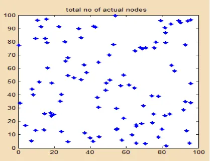
An example simulation scenario composed of total 100 sensor nodes which are randomly deployed.
Fig5:Ideal Placement Of The 100 Sensor Nodes
Fig 6: Detection Of Shortest Path (Shown By Red) From Current Mesh of active nodes(shown by green)
Total no of default nodes = 20
Shortest path (Start node = 1, Finish node = 10)
Optimized shortest path (p) =1 3 5 7 9 10
Distance of shortest path (d) = 329.4321m
Another scenario for 600 nodes
Fig7:Ideal Placement Of The 600 Sensor Nodes
Fig 8: Detection Of Shortest Path(Shown By Red) From Current Mesh of active nodes(shown by green)
Total no of default nodes = 45
Shortest path (Start node = 7 , Finish node = 24)
Optimized path (p) = 7 9 11 13 14 16 18 20 22 24
5. CONCLUSION ANDFUTURE SCOPE
In the proposed shortest path finding network, we have various steps to determine the faulty nodes in the network. We have assumed the total nodes to be consisting of many faulty nodes for showing the case of failure as there is no recovery technique in those areas. Therefore we have to change the direction of information when transmitted from a Sender Node to the Receiver Node. So, in order to optimize the path for efficient communication we provide a methodology for the Retracing of Optimal Path with energy efficient faulty node detection. This assessment becomes the power performance booster as it automatically determines the shortest path after path hopping is traced. A self Management approach links the sensor nodes from the source node to the destination node with in a shortest path and shows distributed accuracy. It also depicts of the amount of path travelled by data to reach the ending node from start node as shown in results, the applications can be machine health monitoring, surveillance, and medical monitoring .It is estimated that by the year 2020 more than 100 billion wireless sensors will be deployed for applications as diverse as environmental monitoring, agricultural monitoring, machine health monitoring, surveillance, and medical monitoring. However, there are many challenges that must be addressed before the full potential of these networks are realized. Wireless sensor networks must be reliable and scalable to support large numbers of unattended wireless sensors; they must last for extended periods of time using limited battery power; they must be secure against outside attacks on the network and on data fidelity; they must be accurate in providing required information while performing in-network processing to reduce data load; and they must interface with existing networks.
REFERENCES
[1] Prasenjit Chanak, Tuhinasamanta ,Indrajit Banerjee Department Of Information Technology Bengal Engineering And Science University, Shibpur , “fault-Tolerant multipath routing Scheme For energy efficient wireless Sensor networks” International Journal of
Wireless & Mobile Networks (IJWMN) Vol. 5, No. 2, April 2013.
[2] Peng Jiang Institute Of Information And Control, Hangzhou Dianzi University, 310018, P.R. China, “A New Method for Node Fault Detection in Wireless Sensor Networks” ,Sensors 2009, 9, 1282-1294; Doi:10.3390/S90201282 Received: 12 September 2008, In Revised Version: 16 February 2009 / Accepted: 17 February 2009 / Published: 24 February 2009.
[3] Ankit Arora1 Sonika Soni2 1 M.tech 2 Assistant Professor 1,2 Department of ECE, JCDMCOE, Sirsa, Haryana, “Distributed Fault Detection and Correction Using Shortest Path Mechanism in Wireless Sensor Networks”. IJSRD - International Journal for Scientific Research & Development| Vol. 2, Issue 05, 2014 | ISSN (online): 2321-0613
[4]L. Paradis and Q. Han, "A Survey of Fault Management in Wireless Sensor Networks," Journal of Network and Systems Management, vol. 15, pp. 171-190, 2007.
[5] M. Yu, H. Mokhtar, and M. Merabti, "A survey on Fault Management in wireless sensor network," in Proceedings of the 8th Annual PostGraduate Symposium on The Convergence of Telecommunications, Networking and Broadcasting Liverpool, UK, 2007.
[6]J. Staddon, D. Balfanz, and G. Durfee, "Efficient Tracing of Failed Nodes in Sensor Networks," in First ACM International Workshop on Wireless Sensor Networks and Applications USA, 2002.
[7] W. L. Lee, A. Datta, and R. Cardell-Oliver, "Network Management in Wireless Sensor Networks," in Handbook of Mobile Ad Hoc and Pervasive Communications : American Scientific Publishers, 2006.
[8] T. Clouqueur, K.Saluja, and P. Ramanathan, "Fault Tolerance in Collaborative Sensor Networks for Target Detection," in IEEE Transactions on Computers , 2004, pp. 320-333.