New Invention in Converting Two Phase to
Three Phase Employing an Induction Machine
S. Kumaravel1, R.Manikandan2, S.R.Rishi Revanth3,V.Suresh4,S.Venkata Subramanian5
UG Student, Dept. of EEE, Imayam Engineering College, Tiruchirappalli, Tamilnadu, India1 UG Students, Dept. of EEE, TRP Engineering College, Tiruchirappalli, Tamilnadu, India2,3,4,5
ABSTRACT: This paper proposes a new topology of converting two phase to three phase which can be used for
domestic and small industrial loads. Three phase conversion are finding increased applications in industrial environment with greater demand for high voltage, high power processing techniques with improved efficiency. Winding changer included in this project, is a device that supplies three phase power from a two phase source to power inductive, resistive and capacitive loads with distinct advantages over any existing converter device. The essential advantage is the improvement in the output voltage signal quality using devices of low voltage rating with lesser switching frequency, thereby increasing the overall efficiency of the system
.
KEYWORDS: winding changer, contactors, unbalance currents, OLR, preventer, phase sequence.
I.INTRODUCTION
Most probably, if any customer wants to run a three phase appliance on a two phase electric power, two phase to three phase convertor is essential. One of the reasons of not giving three phase electric power to the domestic customer is its high cost of connection installation. It’s quite commonly seen that capacitor is employed in two phase to three phase conversion. Several solutions have been proposed, but the objective is to supply a three phase motor from two phase AC mains, it is very common to have only a two phase power grid in residential, commercial, manufacturing, and mainly in rural areas, while the adjustable speed drives may request a three phase power grid. Two phase to three phase AC-AC conversion usually employs a full bridge topology, which implies in ten power switches. This converter is denoted here as conventional topology. This paper describes the working of three phase induction motor using two phase supply for the conversion of two phase to three phase. Once the supply is given, the motor starts rotate at a low speed. After this, the motor can able to run at a rated speed with the help of contactors switches which changeover the end terminal connections. Hence the Third phase is generated and it combines with the existing two phase and the output will be three phase.
II.BLOCK DIAGRAM
The block diagram of two phase to three conversion using induction machine is shown in fig 2.1.
Fig 2.1 Block Diagram
When three phase input is given to relay it operates to provide direct three phase, and if two phase is available winding changer changes the end terminal connections of an induction motor and produces the third phase. Hence the output will be a three phase from two phase.
According to faraday’s law of electromagnetic induction "whenever flux links the coil changes, emf is induced" when an induction motor gets excited by giving alternating current the flux is produced by the stator winding, this flux revolves with the synchronous speed. which is knows as rotating magnetic field(RMF). This rotating magnetic field makes the motor to rotate. By considering four poles, two pairs of brushes (A, B, C, D) induction motor two brushes (A, C) are connected with the supply, armature reactance ø1 flux setup in a low reactance path hence, emf E2=KI1 is setup between B & D brush. When brushes B & D are connected to a load, a current I2 flows through the load. The load current I2 setup another flux ø2 causes an emf, E1=KI2 between the brushes A & C opposing the applied voltage. As the applied voltage is constant, resistance drop is negligible so that the back emf E1 is also constant[1].
III.CIRCUIT DIAGRAM
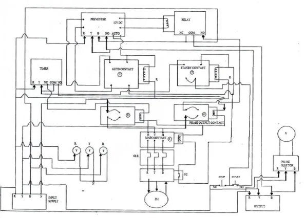
The circuit diagram for conversion of two phase to three phase conversion using contactors is shown in fig 3.1
Fig 3.1 Circuit Diagram
When supply is given, the Preventer operates to check whether the supply is three phase or two phase. If it is two phase supply, the contactors operates to provide three phase output or else the three phase is directly fed from the supply.
IV.PROPOSED APPROACH
IV.i. WINDING CHANGER
The step by step operation of the winding changes is shown in fig
Fig 4.1.1(a) Existing System.
Fig 4.1.2 Proposed system
(a) Step 1.(b) Step 2.(c) Step 3.
Winding changer consists of four contractors which is used to change over the connection in the end terminals.
Contactor 1: This contactor acts as a stand by contactor.
Contactor 2: This allows two phase supply in star connections i.e, (B2,C1) as shown in figure 4.1.2(a).
Contactor 3: This allows two phase supply (C2,A2) in delta connection in which C2,A1 and A2,B1 are shorted as shown in figure4.1.2(b).
Contactor 4: This contactor shorts B2 and C1 and output from 3rd phase is taken as shown in fig 4.1.2(c).
IV. ii UNBALANCED CURRENT
Example: Determine the average from the below table
Phase
Loaded Amps
R
9.5
Y
16.2
B
21.3
Table 1 Current at each phase
(9.5+16.2+21.3)/3 =15.6 amps
Determine the difference percentage
(Highest phase-average )/average *100
(21.3-15.6)/15.6*100 = .38461*100 = 38.48
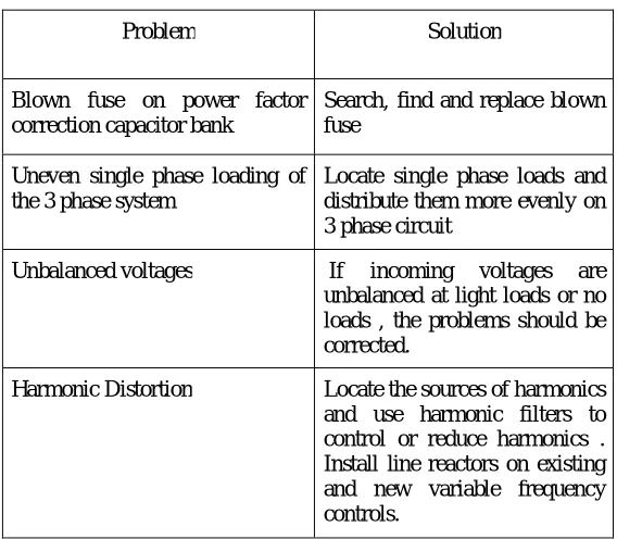
IV.ii.i Effects Of Unbalanced Currents
Problem Solution
Blown fuse on power factor correction capacitor bank
Search, find and replace blown fuse
Uneven single phase loading of the 3 phase system
Locate single phase loads and distribute them more evenly on 3 phase circuit
Unbalanced voltages If incoming voltages are unbalanced at light loads or no loads , the problems should be corrected.
Harmonic Distortion Locate the sources of harmonics and use harmonic filters to control or reduce harmonics . Install line reactors on existing and new variable frequency controls.
IV.iii PHASE SEQUENCE
For the correct operation of 3 phase induction motor, it is necessary to have 3 phase with balance condition.(i.e. 120-degree phase difference between each phase). If the availability of two phase with 120-120-degree phase difference then another phase is generated by connecting one capacitor with any one of the phases. But this operation is quite risky, if we run for more time then the motor winding may be heated and it may burn. This is because of not having the exact 120-degree phase shift.
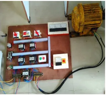
V. HARDWARE OVERVIEW
Fig 5 Hardware Kit
5.1 Hardware Specifications
Parameters Range
Motor 3phase,5Hp,440v
Contactor 16 Amps
VI .CONCLUSION
A two phase to three phase drive system composed of two-phase, a three-phase and an induction motor was proposed. The complete comparison between proposed and standard configuration has been carried out in this paper. Compared to the conventional topology, the proposed system permits to reduce the relay switch currents. In addition, the losses of the proposed system may be lower than that of the conventional counterpart. The initial investment of the proposed system cannot be considered on drawback especially considering the scenario where the justify such initial investment. The experimental results have shown that the system is controlled properly, with transient and occurrence of the fault.
REFERENCES
[1] J.B Gupta, “Utilization of electric power and traction-Metadyne Control” Vol.4 of A course in Electrical Power, Jan.2012.
[2] Zuminen Anthony, “A simple method for operating the three-phase Induction motor on single- phase supply (for wye connection standard)”, International Journal of Engineering Trends & Technology (IJETT), Vol-5, No.1, Nov.2013, ISSN:2231-5381.
[3] Euzeli Cipriano Dos Santos, “Component minimized AC-DC-AC single-phase to three-phase four wire connection”, IEEE Transactions on Industrial Electronics, Vol.58, no.10, October-2011, ISSN:0278-0046.
[4] Prasad N.Enjeti, Ashek Rahman, and Ranjit Jakkli, “Economic Single-Phase to Three Phase Converter Topologies for Fixed and Variable Frequency Output”, IEEE Transactions on Power electronics, Vol.8, NO. 3, July 1993.
[5] Naung Cho Wynn and Tun Lin naing, “Single PhaseThree Phase Converter”, World Academy of Science, Engineering and Technology 42,2008,pp343-347.
[6] P. Enjeti and A.Rahman, “A new single phase to three phase converter with active input current shaping for low cost AC motor drives”,IEEE Trans. Ind. Appl., vol. 29, no.2, pp.806.813, July/Aug.1993.
[7] J. Itoh and K. Fujita, “Novel unity power factor circuits using zero-vector control for single phase input systems”, IEEE Trans.Power Electronics., vol. 15, no.1,pp.36.43, Jan.2000.
[8] R. Q. Machado, S. Buso, J. A. Pomilio and F. P. Marafao, . Three-Phase to single phase direct connection rural cogeneration systems, in Proc.IEEE APEC, 2005, pp.1547.1553.
[9] O. Ojo, W.Zhiqiao, G.Dong, and S.Asuri,. High performance speed sensorless control of an induction motor drive using a minimalist single phase PWM converter,. IEEE Trans. Ind. Appl., vol. 41, no.4, pp.996.1004, July/Aug.2005.
[10] D. J. Nowak, A. Bendre, G. Oriti, and A.L. Julin, “Mitigating circulating common-mode currents between parallel soft switched drive systems”, IEEE Trans. Ind. Appl., Vol.43, no. 5, pp. 1284-1294,. R.M. Cunzer, Sept/Oct.2007.