A Simple Reconfiguration of Sensor to Sensor
Less Control in BLDC Motor - Based EVs
N.Rajendran, S.P.Vijayaragavan
Professor, Dept. of EEE, Bharath University, Chennai, Tamil Nadu, India
Assistant Professor, Dept. of EEE, Bharath University, Chennai, Tamil Nadu, India
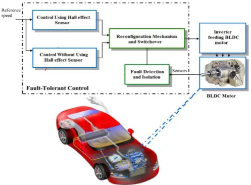
ABSTRACT: This project deals with a reconfiguration strategy for sensor fault-tolerant control (FTC) in brushless DC motor based electric vehicle. The proposed active FTC system is based on two control techniques: Hall effect sensor in the case of healthy sensors and sensor less control method based on current feedback in the case of failed hall sensors. The main objective behind the reconfiguration from one control to another sensor-less control is to achieve a short and smooth transition when switching from a controller to another sensor less controller in the case of a sensor failure. The scheme describes the modeling of brushless DC motor drive based on sensored and sensor-less control methods. For sensored control, commutation logic is obtained from rotor position detection using hall effect sensor feedback. for sensor less control, it is obtained from current feed-back form the BLDC motor. The motor operations are modelled in MATLAB/SIMULINK the entire drive is simulated.
KEYWORDS: fault-tolerant control, Brush Less DC motor , Reconfiguration, Hall effect sensor and Electric vehicle.
I.INTRODUCTION
In recent days, fault-tolerant control (FTC) has become a concern a wider range of industrial applications such as space research, automobile, nuclear power, manufacturing, etc. [1]–[3]. Indeed, a significant amount of research on FTC systems was carried out for critical loads like aircraft flight control system designs [4] and nuclear power plants [5]. Fault tolerance is no longer limited to high-end systems but is implemented in areas such as railway [6] and automobile applications [7]. The need for FTC became an important means to increase the reliability, availability, and continuous operation of electromechanical systems [9], [10].
Brush Less DC Motor control depends on the availability and quality of sensor measuring the rotor position. Measurements, however, can be corrupted or interrupted due to sensor faults. If some sensors are damaged due to higher temperature or due to mechanical damage, the controllers cannot provide the correct control actions for the drive. Sensor FTC is therefore compulsory to maintain a minimum level of performance in terms of quality. In the particular case of special machines like Brush Less DC Motor which cannot operate without rotor position feedback, as the adopted drive, many fault detection and diagnosis schemes based on vibrations and stator current spectrum analysis have been reported. Regarding the BLDC motor, a number of hall sensor FTC schemes have been proposed[11]
Fig 1 BLDC motor drive system
Indeed, it has been suggested that controller transition could be better handled with a fuzzy approach. The system control reorganization is managed by a fuzzy decision system that ensures the transition from the encoder-based controller (sliding mode control) to the sensorless one (fuzzy control) and back to the encoder-based controller. However, the achieved transition dynamic performances were not satisfactory in terms of speed and torque ripples. In [7], the proposed system was based on four controllers to ensure the sensor FTC of an EV induction motor-based power train, for various sensors faults. In this case, the control transition smoothness depends greatly upon the rotor flux angular position in the stator reference frame. Smooth transition is achieved when the phase shift is zero or very close to zero. Unfortunately, it is very difficult to get this condition. This will lead to quite important braking torque with probably mechanical damages.
This project deals with a reconfiguration strategy for sensor fault-tolerant control (FTC) in brushless DC motor. The proposed active FTC system is illustrated using two control techniques: Hall effect sensor in the case of healthy sensors and Back emf difference method in the case of failed hall sensors. The main objective behind the reconfiguration strategy is to achieve a short and smooth transition when switching from a controller using a healthy sensor to another sensor less controller in the case of a sensor failure. The scheme describes the modeling of brushless DC motor drive based on sensored and back emf zero crossing control detection. For sensored control, commutation logic is obtained from rotor position detection. for sensor less control, it is obtained from back EMF difference method.[19-21]
In [11], Discrete Fourier transform analysis is used for pattern recognition of the line voltages of BLDC motor. Hall Effect sensor failure of BLDC motor is implemented on the verified simulation model. A knowledge based table is developed to identify the faulty sensor by analyzing the simulation results.[22-23] Hence faulty position sensor is identified through spectral density error of the line voltages. Commutation signal of faulty sensor is generated by microcontroller through correlation between Hall signals. The proposed fault tolerant system is capable to detect, identify and rectify the Hall Effect sensor break down in BLDC motor. Effectiveness of the remedial strategy is also proven by correct performance of BLDC motor under faulty condition.
proposed system has a simple algorithm.
II. MODELLING OF BLDC MOTOR
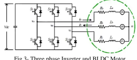
BLDC drive with sensor, consist of a BLDC motor, control circuit and Hall sensor for position information. By knowing the position information, inverter switches are commutated by generating PWM signals with the suitable duty ratio. Three Hall sensors are used for position detection of the BLDC motor. A general BLDC motor has three phase stator windings and is driven by an inverter which constitutes of six switches. Fig. 1 shows the equivalent circuit of a star connected BLDC motor and the inverter topology [12][13][24]
The modeling is based on the following assumptions: (1) The motor is not saturated.
(2) Stator resistances of all windings are equal and self and mutual inductances are constant. (3) Power semiconductor devices in the inverter are ideal.
(4) Iron Losses are negligible.
Fig 3- Three phase Inverter and BLDC Motor
The voltage equation of a BLDC motor can be expressed as:
Where
Va, Vb and Vc are the stator phase voltages; R is the stator resistance per phase; Ia, Ib and Ic are the stator phase currents;
L is the self-inductance per phase and ea, eb and ec are the back electromotive forces. BEMF equation of each phase should be as follows:
where
Kw is back EMF constant of one phase [V/rad.s-1], θe - electrical rotor angle [° el.],
ω - rotor speed [rad.s-1].
Total torque output is given by:
where
Te is total torque output [Nm], Also,
where
TL - Load torque [Nm],
J - Inertia of rotor and coupled shaft [kgm2], B - Friction constant [Nms.rad-1]. The electrical rotor angle is equal to the mechanical rotor angle multiplied by the number of pole pairs p:
Where θm is mechanical rotor angle [rad].
III. FAULT DIAGNOSIS
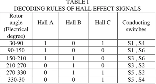
Each Hall Effect signal of BLDC motor has specific value at each instant of time with respect to permanent magnet rotor position. Electronic commutation is done by decoding the position sensor signals. Decoding rules of Hall Effect signals to choose a proper switching vector of VSI are shown in Table III. As it can be seen in table there is no condition that all three hall signals being one or zero at a same time.
TABLE I
DECODING RULES OF HALL EFFECT SIGNALS Rotor
angle (Electrical
degree)
Hall A Hall B Hall C Conducting switches
30-90 1 0 1 S1 , S4
90-150 1 0 0 S1 , S6
150-210 1 1 0 S3 , S6
210-270 0 1 0 S3 , S2
270-330 0 1 1 S5 , S2
330-30 0 0 1 S5 , S4
The addition of Hall signals introduced by (1) is a fault signature for Hall Effect sensors breakdown. Maximum possible value of Hf is 2, where the minimum possible value is 1 (1 < Hf < 2) for each specific electrical angle section. If Hf value goes over of these limits Hall Effect sensor failure is detected. Hall Effect sensors Fault Flag (HFF) is introduced for sensor fault detection. HFF is set to ‘1‘ if Hf value is more than 2 (it means that one of the position sensor signals is constant one), HFF is set to ‘-1‘ if Hf value is less than 1 (it means that one of the position sensor signals is constant zero) and HFF is ‘0‘ in case of no fault. Maximum fault detection time is the time of on electrical rotation of rotor which is quite fast.
Energy Density (SED) of computed frequency spectrum is determined by (3). SED difference of successive time intervals are calculated and analyzed to identify the faulty position sensor.[25]
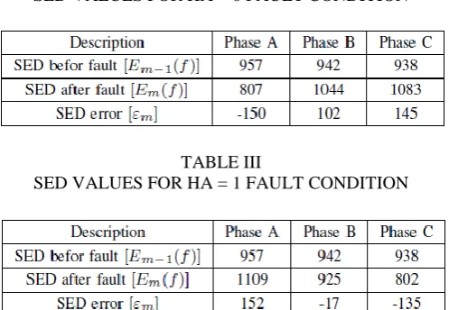
Calculated SED errors of the BLDC motor line voltages for Hall Effect sensor failure of phase A for HA = 0 and HA = 1 faults are shown respectively in Table IV and Table V. As it is shown in the tables, it is possible to distinguish two failure conditions of Hall Effect sensor through SED errors. The simulation model is also run for position sensor faults of phases B and C. The line voltages of BLDC motor for Hall Effect sensor faults of all phases are studied through the simulation model.
TABLE II
SED VALUES FOR HA = 0 FAULT CONDITION
TABLE III
SED VALUES FOR HA = 1 FAULT CONDITION
Hall Effect Identification Flag (HIF) of each phase is introduced for faulty sensor identification. Numeric values are given to HIF of each phase according to SED errors of all three line voltages of BLDC motor as below,
HIF is ‗-1‘ if SED error is negative.
HIF is ‗1‘ if SED error is positive.
TABLE IV
RULE BASED POSITION SENSOR FAULT IDENTIFICATION TABLE
III. IMPLIMENTATION AND SIMULATION RESULT PULSE GENERATION
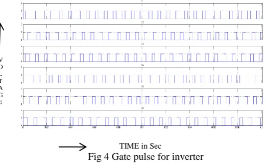
Gate pulse for switches S1,S2,S3,S4,S5 and S6 are obtained from feed back signal obtained either from hall sensor or from back emf, with the the help of pulse generation circuit which are discussed in the previous chapter.the pulse pattern for the inverter working with hall sensor is shown in the figure 4
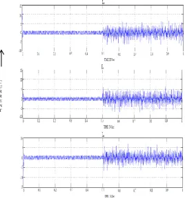
STATOR CURRENT AND STATOR BACKEMF
The stator current and stator back emf of phase is taken from the bldc motor with the scope connected with it. The waveform for stator current and back emf of phase A is shown in Fig 5. The magnitude of stator current is uniform when the brush less DC motor operates with hall sensor. When the motor operates with out hall sensor feed back the magnitude of stator current is large with ripples. The back emf is not affected with the different controls.
TIME in Sec
Fig 4 Gate pulse for inverter
V O L T A G E
Fig 5 Stator current and stator back-emf of phase A of BLDC motor
MOTOR SPEED
The motor speed in revolution per minute is taken form the motor with the help of scope. Fig 6 shows the motor speed with respect to time. The magnitude of motor speed is ripple free when the brush less DC motor operates with hall sensor. When the motor operates with out hall sensor the motor speed has more ripples.
Fig 6 The motor speed with respect to time
MOTOR TORQUE
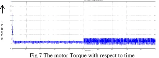
The motor torque in Newton meter is taken form the motor with the help of scope. Fig 4.9 shows the motor torque with respect to time. The magnitude of motor torque is ripple free when the brush less DC motor operates with hall sensor. When the motor operates with out hall sensor the motor speed has more ripples.
Fig 7 The motor Torque with respect to time
INPUT VOLTAGE
The voltage between the phases is taken with the help of voltage measuring device and is viewed with the help of scope. The voltage waveform is shown in Fig 8. The input voltage to the brush less DC motor is not affected with the different controls.its magnitude is 300 volt.
S P E E D
Fig 8 Input voltage to the BLDC motor
INPUT CURRENT
The voltage through the line is taken with the help of current measuring device and is viewed with the help of scope. The current waveform is shown in Fig 4.13. The magnitude of motor input current is ripple free when the brush less DC motor operates with hall sensor. When the motor operates with out hall sensor the motor input current has more ripples.
Fig 9 Input current to the BLDC motor
PARAMETERS USEDIN SIMULATION
Parameters Values POWER 1000 Watt DC VOLTAGE 500 Volt SPEED 1400 rpm PHASE RESISTANCE (R) 12.5 Ohm PHASE INDUCTANCE (L) 0.4 mH POLES 4
IV. CONCLUSION
This paper deals with a reconfiguration strategy for sensor fault-tolerant control (FTC) in brushless DC motor. The proposed active FTC system is illustrated using two control techniques: Hall effect sensor in the case of healthy sensors and Back emf difference method in the case of failed hall sensors. The main objective is the reconfiguration strategy is to achieve a short and smooth transition when switching from a controller using a healthy sensor to another sensor less controller in the case of a sensor failure is obtained. The scheme describes the modeling of brushless DC motor drive based on sensored and back emf zero crossing control detection. For sensored control, commutation logic is obtained from rotor position detection. for sensor less control, it is obtained from back EMF difference method. They prove the effectiveness of the active FTC approach. It can be observed that the performance of brush less DC motor is influenced with hall sensor. Though the sensorless control is cheaper compare to the system with hall sensor but the output performance of motor is reduced.
REFERENCES
[1] M. Bruccoleri, M. Amico, and G. Perrone, ―Distributed intelligent control of exceptions in reconfigurable manufacturing systems,‖ Int. J. Prod. Res.,vol. 41, no. 7, pp. 1393–1412, May 2003.
[2] Subha Palaneeswari M., Abraham Sam Rajan P.M., Silambanan S., Jothimalar, "Blood lead in end-stage renal disease (ESRD) patients who were on maintainence haemodialysis", Journal of Clinical and Diagnostic Research, ISSN : 0973 - 709X, 6(10) (2012) pp.1633-1635.
[3] Jeyanthi Rebecca L., Dhanalakshmi V., Sharmila S., "Effect of the extract of Ulva sp on pathogenic microorganisms", Journal of Chemical and Pharmaceutical Research, ISSN : 0975 – 7384 , 4(11) (2012) pp.4875-4878.
[4] Sharmila D., Saravanan S., "Efficacy of lead on germination growth and morphological studies of Horse Gram (Dolichos biflorus Linn)", Journal of Chemical and Pharmaceutical Research, ISSN : 0975 – 7384 , 4(11) (2012) pp.4894-4896.
[5] R. Isermann, R. Schwarz, and S. Stolzl, ―Fault-tolerant drive-by-wire systems,‖ IEEE Control Syst. Mag., vol. 22, no. 5, pp. 64–81, Oct. 2002. [6] M. G. Mehrabi, A. G. Ulsoy, Y. Koren, and P. Heytler, ―Trends and perspectives in flexible and reconfigurable manufacturing systems ,‖J.
Intell. Manuf., vol. 13, no. 2, pp. 135–146, 2002.
[7] Sharmila S., Rebecca L.J., Saduzzaman M., "Effect of plant extracts on the treatment of paint industry effluent", International Journal of Pharma and Bio Sciences, ISSN : 0975-6299, 4(3) (2013) pp.B678-B686.
[8] Saduzaman M., Sharmila S., Jeyanthi Rebecca L., 'Efficacy of leaf extract of Moringa oleifera in treating domestic effluent", Journal of Chemical and Pharmaceutical Research, ISSN : 0975 – 7384, 5(2) (2013) pp.139-143.
[9] M. Steinberg, ―Historical overview of research in reconfigurable flight control,‖ Proc. IMechE Part G, J. Aerospace. Eng., vol. 219, no. 4, pp. 263–275, 2005.
[10] Y. Zhang and J. Jiang, ―Bibliographical review on reconfigurable fault tolerant control systems,‖ Ann. Rev. Control, vol. 32, no. 2, pp. 229– 252,Dec. 2008.
[11] S.M. Bennett, R. J. Patton, and S. Daley, ―Sensor fault-tolerant control of a rail traction drive,‖ControlEng.Pract., vol. 7, no. 2, pp. 217–225, Feb.1999.
[12] D. Diallo, M. E. H. Benbouzid, and A. Makouf, ―A fault-tolerant control architecture for induction motor drives in automotive applications,‖
IEEE Trans. Veh. Technol., vol. 53, no. 6, pp. 1847–1855, Nov. 2004.
[13] M. Muenchhof, M. Beck, and R. Isermann, ―Fault-tolerant actuators and drives—Structures, fault detection principles and applications,‖ Ann. Rev. Control, vol. 33, no. 2, pp. 136–148, Dec. 2009.
[14] D. U. Campos-Delgado, D. R. Espinoza-Trejo, and E. Palacios, ―Fault tolerant control in variable speed drives: A survey,‖ IET Elect. Power Appl., vol. 2, no. 2, pp. 121–134, Mar. 2008.
[15] M. E. H. Benbouzid, D. Diallo, and M. Zeraoulia, ―Advanced faulttolerant control of induction-motor drives for EV/HEV traction applications:From conventional to modern and intelligent control techniques,‖ IEEE Trans. Veh. Technol., vol. 56, no. 2, pp. 519–528, Mar. 2007.
[17] S. Ogasawara and H. Akagi, ―An approach to position sensorless drive for brushless dc motors,‖ IEEE Trans. Ind. Appl., vol. 27, no. 5, pp. 928–923, Sep./Oct. 1991.
[18] P. Pillay and R.Krishnan, ―Modelling, Simulation, and analysis of permanent-magnet motor drives‖, IEEE Trans. Ind. Appl, vol. 25, no. 2, pp. 265-279, Mar/Apr 1989.
[19] E. Balaban, A. Saxena, P. Bansal, K. Goebel, and S. Curran, ―Modeling,detection, and disambiguation of sensor faults for aerospace applications,‖IEEE Sensors Journal, vol. 9, no. 12, pp. 1907–1917, 2009.
[20] N. B. Samoylenko, Q. C. Han, and J. Jatskevich, ―Dynamic performance of brushless dc motors with unbalanced hall sensors,‖ IEEE Transactions on Energy Conversion, vol. 23, no. 3, pp. 752–763, 2008.
[21] Lingeswaran, K., "Microcontroller-based MPPT control for standalone PV system with sepic converter", Middle - East Journal of Scientific Research, v-20, i-8, pp:945-950, 2014.
[22] Thamarai, P., Karthik, B., Kumaran, E.B., "Optimizing 2:1 MUX for low power design using adiabatic logic", Middle - East Journal of Scientific Research, v-20, i-10, pp:1322-1326, 2014.
[23] Jayalakshmi, V., "Wireless sensor network for performance monitoring of electrical machine", Middle - East Journal of Scientific Research, v-20, i-8, pp:996-999, 2014.
[24] Prasad, K.S., "A design towards smart batteries", Middle - East Journal of Scientific Research, v-20, i-10, pp:1318-1321, 2014.