An Efficient MPPT Control Algorithm for
Solar Power Plant Battery Charging System
with the Improved Steady State Response
C.Mohan Raj
1, Dr.T.Vijaya Kumar
2, R.Suresh Kumar
3Assistant Professor, Dept. of EEE, Sri Eshwar College of Engineering, Coimbatore, Tamilnadu, India 1
Professor and Head, Dept. of EEE, Sri Eshwar College of Engineering, Coimbatore, Tamilnadu, India 2
Senior Engineer, R&D Division, ELGI Equipments, Coimbatore, Tamilnadu, India 3
ABSTRACT: This paper presents an efficient MPPT (Maximum Power Point Tracking) control algorithm for the solar power generating plant battery charging system with improved steady/dynamic performance. Solar panels are constructed by the series connection of „n‟ number of PV cells and the PV panels are operated in parallel/series to charge the battery. Battery state of charging (SOC) is decided by the charging voltage and charging current. The charging voltage and current is mainly supplied by the PV array modules. For efficient charging, the PV panel must be operated in the maximum power region irrespective of the battery terminal voltage and environmental conditions. In general, PV panel efficiency is high in winter season and low in summer season due to environmental temperature. The process of extracting maximum power always from the PV panels is called MPPT technique. MPPT power electronic controller is located in between the PV panels and the Battery. The buck-boost converter duty cycle is adjusted to get maximum power from the panel. Panel Voltage and Current is sensed by the voltage shunt and current shunt arrangement and it is given to the MPPT controller. The reference power is compared with the actual power generated by the PV Modules and the duty cycle of the MPPT power electronic controller is modified to match the PV power to the reference power value. In this paper, battery charging voltage/current ripples are eliminated by an effective MPPT P&O algorithm.
KEYWORDS: MPPT algorithm, SOC, MPPT controller, PWM pulses, Battery charging, DC voltage ripples, P&O algorithm
I.INTRODUCTION
Now a day‟s renewable energy based power generation plays a vital role in power sector. Most of the energy is obtained from the wind and solar when compare to all other renewable resources like Tidal, Biomass…etc. Among all renewable energy resources, solar is one of the most available and abundance resource. Solar panels are used to convert the light energy into an electrical energy. This electrical energy is stored in the Battery. Using suitable Inverter technology, the stored electrical energy in the battery is tie up with the AC grid. The solar power plant efficiency is mainly decided by the effective storage of electrical energy in the battery. Now a days the main problem in this solar power generation are designing of suitable charge controller for storing the electrical power in the battery and making an efficient solar panels for very good energy conversion. Making an efficient panel is full and full based on the type of technology and quality of the materials (Mono crystalline or poly crystalline silicon materials). The one way to achieve the maximum efficiency in the panel is designing the suitable MPPT controller with powerful algorithm. Solar tracking system is also employed in previous research work to obtain the maximum power and efficiency from the panels. But this system has poor response when the sun light is absent condition and low light intensity condition.
voltage. In the short term, not using an MPPT controller will result in a higher installation cost and, in time, the costs will escalate due to eventual equipment failure.
The above said difficulties can be overcome by placing the suitable MPPT controller in between the solar panel and the battery. Using an efficient MPPT algorithm, the maximum power is always extracted from the solar panel and the charge controller output voltage is adjusted to avoid over charging of the battery and to achieve the better panel utilization factor [1-5]. The basic block diagram of Solar-MPPT technique is shown in Fig.1.
Fig.1. Basic block diagram of MPPT controller scheme
II
.MODELLING OF PV SYSTEMA solar cell is comprised of a P-N junction semiconductor that produces currents via the photovoltaic effect. PV arrays are constructed by placing numerous solar cells connected in series and in parallel [5]. A PV cell is a diode of a large-area forward bias with a photo voltage and the equivalent circuit is shown by Figure 2
. Fig.2. Equivalent circuit of a PV cell
The current-voltage characteristic of a solar cell is derived from the equation as follows:
……..(1)
Where,
Iph = photocurrent,
ID = diode current,
I0 = saturation current,
A = ideality factor,
q = electronic charge 1.6x10⁻⁹,
kB = Boltzmann‟s gas constant (1.38x10⁻²³),
Rsh = shunt resistance,
I = cell current, V = cell voltage
Typically, the shunt resistance (Rsh) is very large and the series resistance (Rs) is very small [5]. Therefore, it is common to neglect these resistances in order to simplify the solar cell model.
……… (2)
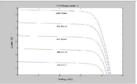
The resultant ideal voltage-current characteristic of a photovoltaic cell is given by (17) and illustrated by Figure 3. [6-8] The typical output power characteristics of a PV array under various degrees of irradiation is illustrated by Figure 3. It can be observed in Figure 4 that there is a particular optimal voltage for each irradiation level that corresponds to maximum output power. Therefore by adjusting the output current (or voltage) of the PV array, maximum power from the array can be drawn.
Fig.3. Solar Panel V-I characteristics
Fig.4. Solar panel Voltage-Power characteristics
III.SOLAR PANEL MPPT TECHNIQUE
The MPPT algorithms automatically find the panel operating voltage that allows maximum power output. A typical solar panel power graph (Figure 3) shows the open circuit voltage to the right of the maximum power point. In general, solar panels have the following parameters:
Maximum Power Voltage (VMP)
Maximum Current (IMP)
Open circuit Voltage (Voc)
Short circuit Current (Isc)
The open circuit voltage (VOC) is obviously the maximum voltage that the panel outputs, but no power is drawn. The short-circuit current of the panel (ISC) is another important parameter, because it is the absolute maximum current can be get from the panel. The maximum amount of power that can be extracted from a panel depends on three important factors: irradiance, temperature and load.
MPPT or Maximum Power point Tracking is an algorithm that's included in charge controllers used for extracting maximum available power from PV solar module under certain conditions.
The voltage at which PV modules can produce maximum power is called „maximum power point‟ (or peak power voltage, Vmp). Maximum power varies with solar radiation (sunshine & cloud), ambient temperature and solar cell temperature.
The basics of Maximum Power Point Tracking (MPPT) Solar Charge Controller are an electronic tracking, and have nothing to do with moving the panels with a mechanical solar tracker. Instead, the controller looks at the output of the panels, and compares it to the battery voltage.
MPPT controller calculates the best power that the panel can put out to charge the battery. It takes this and converts it to the best voltage to get maximum AMPS into the battery. Using technology called a buck-boost power electronic converter.
Maximum Power = VMP * IMP (Watts)
Consider the panel with maximum power of 240Watts, VMP of 24V and IMP of 10A.
Case 1: Suppose if the solar panel is directly connected to the battery without MPPT controller and the battery voltage is 10V initially and the produced VMP of 24V and IMP of 10A.
Fig.5. Direct connection of Solar panel with the battery
In this case, the solar panel 24V is pull-down to 10 V (battery voltage). So the maximum power transferred to the battery is only 100W, i.e.
Power transferred to the battery = V*I = 10*10
= 100Watts
Case 2: If the MPPT controller is installed in between the Solar panel and the battery
Here the panel produces the maximum power of 240W with VMP of 24V and IMP of 10A. In this case the battery is not directly connected to the PV panels. MPPT controller decides the battery charging voltage in order to get the maximum power transfer. The input of the MPPT controller is VMP of 24 V and IMP of 10A. But the output of the MPPT controller is connected to the battery. In the output side, the charging voltage and charging current are modified to get the maximum Power.
In this case, the output of the MPPT controller is around 10V or slightly higher and the Amps rating is 24A. Power transferred to the battery = V*I
= 10*24 = 240Watts
This arrangement works as a dc-dc transformer. Solar panel generated power is transformed to battery with different voltage and current level.
Buck-boost converter primary power = Buck-boost converter secondary power
Vpy*Ipy = Vsy*Isy
Where,
Vpy – Solar panel produced voltage in Volts
Ipy – Solar panel produced current in Amps
Vsy – Charging Voltage at the battery terminals in Volts
Isy – Charging current of the battery in Amps
The MPPT controller adjusts the battery charging voltage with respect to the present voltage level or charging condition of the battery.
IV.PERTURB AND OBSERVE (P&O) ALGORITHM
P&O is one of the most efficient algorithms for MPPT. The algorithm involves introducing a perturbation in the panel operating voltage. Modifying the panel voltage is done by modifying the converter duty cycle. Looking at Figure 5 makes it easy to understand that decreasing voltage on the right side of the MPP increases power. Also, increasing voltage on the left side of the MPP increases power. This is the main idea behind P&O.
Let‟s say that, after performing an increase in the panel operating voltage, the algorithm compares the current power reading with the previous one. If the power has increased, it keeps the same direction (increase voltage), otherwise it changes direction (decrease voltage). This process is repeated at each MPP tracking step until the MPP is reached. After reaching the MPP, the algorithm naturally oscillates around the correct value.
The basic algorithm uses a fixed step to increase or decrease voltage. The size of the step determines the size of the deviation while oscillating about the MPPT. [9-10]
Having a smaller step will help reduce the oscillation, but will slow down tracking, while having a bigger step will help reach MPP faster, but will increase power loss when it oscillates.
To be able to implement P&O MPPT, the application needs to measure the panel voltage and current. While implementations that use only one sensor exist, they take advantage of certain hardware specifics, so a general purpose implementation will still need two sensors.
V. MATLAB SIMULATION RESULTS OF MPPT
The MPPT algorithm is implemented in the MATLAB software and the results were taken. The Simulink diagram of the proposed battery charging system and their results were shown in figures below.
Fig.8. Simulation diagram of an Efficient MPPT technique
MPPT ALOGRITHM:
Fig.9. Simulation subsystem diagram of P&O algorithm
BOOST CONVERTER SUBSYSTEM
:
Fig.11. Simulation subsystem diagram of Boost converter PWM generation
(a)
(b)
(d)
(e)
(f)
Fig.12.Simulation results (a) PV cell voltage and current (b) Buck – Boost converter output (Boost up) voltage and current (c) Solar panel power matches the load power. (d) Solar Panel power and the load power (e) Buck-Boost
converter PWM signal (f) SOC (State Of Charging) of battery from 0V to 220V
VI.CONCLUSION
life of the battery. VSI (Voltage Source Inverter) based VFD (Variable Frequency Drives) use this scheme for obtaining constant DC link voltage for efficient motor speed/torque control operations
.
REFERENCES
[1] Bo Yang, Wuhua Li, Member, IEEE, Yunjie Gu, Wenfeng Cui, and Xiangning He, Fellow, “Improved Transformerless Inverter With Common-Mode Leakage Current Elimination for a Photovoltaic Grid-Connected Power System” IEEE Transactions on Power Electronics, Vol. 27, no.2, February 2012.
[2] Jonathan Scott, “Vehicle lead acid battery SOC meter”, IEEE conference publications, pages 1660-1664, Nov 2011.
[3] Jing Jun Soon and Kay-Soon Low, Senior Member, IEEE “Photovoltaic Model Identification Using Particle Swarm Optimization With Inverse Barrier Constraint” IEEE Transactions On Power Electronics, Vol. 27, no.9, September 2012.
[4] M.A.Elgendy, Bashar Zahawi, David.J.Atkinson, „‟Assessment of Perturb and Observe MPPT algorithm technique for PV Pumping Applications‟‟, IEEE Transaction, Vol. 3, no.1, January 2012.
[5] Minsoo Jang, Mihai Ciobotaru and Vassilios.G.Agelids, “A Single – Phase Grid Connected Fuel Cell System Based on a Boost Inverter”, IEEE Vol.28, no.1, January 2013.
[6] Nasrudin A. Rahim, Senior Member, IEEE, Krismadinata Chaniago, Student Member, IEEE, and Jeyraj Selvaraj “Single-Phase Seven-Level Grid-Connected Inverter for Photovoltaic System” IEEE Transactions On Industrial Electronics, Vol. 58, no.6, June 2011.
[7] Prajna Paramita Dash, Student Member, IEEE, and Mehrdad Kazerani, Senior Member, IEEE “Dynamic Modeling and Performance Analysis of a Grid-Connected Current-Source Inverter-Based Photovoltaic System”, IEEE Transactions On sustainable energy, Vol. 2, no.4, October 2011.
[8] S. B. Kjaer, J. K. Pedersen, and F. Blaabjerg, “A review of Single-Phase Grid-Connected Inverters for Photovoltaic Modules” IEEE Trans. Ind. Appl., vol. 41, no. 5, pp. 1292–1306, Oct. 2005.
[9] Yoshifumi Morita,Sou Yamamoto, SunHee Lee and Noaki Mizuno,”Online Detection of SOC in Lead Acid Battery using both Neural and Online Identification”, IEEE Transaction on Power electronics Vol.8, no.7,Spetember 2006.