Multi Area Thermal System with Automatic
Generation Control for Fuzzy Logic Controller
using TCPS-SMES
E.DURGA PRA SA D M-tech Student Scholar
Department of Electrical & Electronics Engineering, HELAPURI Institute of Technology & Science, Eluru,
West Godavari (Dt); A.P, India.
P.VICTOR BA BU Assistant Professor
Department of Electrical & Electronics Engineering, HELAPURI Institute of Technology & Science, Eluru,
West Godavari (Dt); A.P, India. A BSTRACT: Automatic generation control has been used for
several years t o meet the objective of maintaining the system frequency at nominal value and t he net t ie line power int erchange from different areas at their scheduled values. The concept of conventional AGC is discussed. Controlling the frequency has always been a major subject in electrical power system operation and is becoming much more significant recently with increasing size, changing structure and complexity in int erconnected p ower sy stems. T he power s ystems are widely interconnected for its applicability all over t he globe. Interconnection not only enhances system reliability but also improves t he system efficiency. Since the system is wide and complex, for the faithful operation, the analysis of the
s ystem is of greater importance.The proposed TCPS-SMES
combination can improve the dynamic system performance of Automatic Generation Control of an interconnected system aft er the sudden load perturbation. The integral gains of AGC are obtained by tuning the quadratic performance index using Integral Squared Error (ISE) technique. The system is modelled using M AT LAB SIM ULINK.
Keywords: A GC, TCPS-SMES, multi area controller, fuzzy logic controller.
I. INTRODUCTION
The main objective of power system utility is to maintain continuous supply of electrical power with an acceptable quality, to all the consumers in the system. The power system will be in equilibrium, when there is a balance between electrical power demand and the power generated. There are two basic control mechanisms used to achieve reactive power balance (acceptable voltage profile) and real power balance (acceptable frequency values). The former is called Automatic Voltage Regulator (AVR) and latter is called Automatic Generation Control (AGC) [1]. The goal of AGC in an interconnected power system is to minimize the transient deviations in area frequency, tie-line power interchange and to ensure their steady state errors to be zeros [2]. A considerable drop in frequency could result in high magnetizing currents in induction motors and transformers. The wide-spread use of electric clocks and the use of frequency for other timing purposes require accurate maintenance of synchronous time which is proportional to frequency as well as its integral.
According to Indian Electricity Grid Code (IEGC), if the rated system frequency is 50 Hz and the target range for frequency control should be 49.0 Hz–50.0 Hz, the statutory acceptable limits are 48.5–51.5 Hz. However, the users of the electric power change the loads randomly and momentarily. This results in sudden appearance of generation-load mismatches. The mismatch power enters into/drawn for the rotor thus causing a change generator speed and hence the system frequency (as frequency is closely related to the generator speed). It is impossible to maintain the balances between generation and load without control. So, a control system is essential to cancel the effects of the random load changes and to keep the frequency at the standard value. The AGC loop continuously regulates the active power output of the generator to match with the randomly varying load [3].
Literature survey shows that most of the work concerned with Automatic Generation Control (AGC) of interconnected power systems pertain to tie-line bias control strategy [4]. Supplementary controllers are designed to regulate the area control errors to zero effectively. Even in the case of small load disturbances and with the optimised gain for the supplementary controllers, the power frequency and the tie-line power deviations persist for a long duration. In these situations, the governor system may no longer be able to absorb the frequency fluctuations due to its slow response [5]. Thus, to compensate for the sudden load changes, an active power source with fast response such as a Superconducting Magnetic Energy Storage (SMES) is expected to be the most effective countermeasure [6].
system control has been widely accepted in the form of Flexible AC Transmission Systems (FACTS) which provide more flexibility in power sys tem operation and control. This extra flexibility permits the independent adjustment of certain system variables such as power flows, which are not normally controllable. A Thyristor Controlled Phase Shifter (TCPS) is expected to be an effective apparatus for the tie-line power flow control of an interconnected power system. In the analysis of an interconnected power system, some areas are considered to be the channels of disturbances and in this situation, the conventional frequency control, i.e. the governor may fail to attenuate the large frequency oscillations due to its slow response. At the same time, tie-line power flow control by TCPS installed in series with a tie-line in between the two areas of an interconnected power system has the possibility to control the system frequency positively. Ample applications of TCPS for the improvement of dynamic and transient stabilities of power systems have been reported in the literature [10-13]. However, no attempt has been made to improve the performance of AGC of interconnected power systems considering TCPS in series with the tie-line.
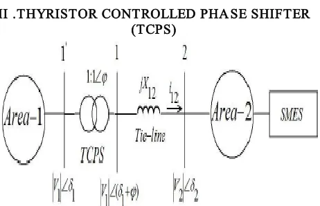
II .THYRISTOR CONTROLLED PHA SE SHIFTER (TCPS)
Fig. 1. Schematic diagram of two area system with T CPS & SMES.
TCPS is a device that changes the relative phase angle between the system voltages. Therefore the real power flow can be regulated to mitigate the frequency oscillations and enhance power system stability [7]. In this study, a two-area multi-unit thermal power system interconnected by a tie-line is considered. Fig. 1 shows the schematic representation of the two-area interconnected power system considering a TCPS in series with the tie-line. TCPS is placed near Area 1. Practically, in an interconnected power system, the reactance to-resistance ratio of a tie-line is quite high and the effect of resistance on the dynamic performance is not that significant. Because of this, the resistance of the tie-line is neglected.
Su p erconducting Magnetic En erg y Sto rag e (SM ES) The SMES unit contains a DC superconducting coil and a 12-pulse converter, which are connected to grid through a Y-Δ/Y-Y transformer. The superconducting
coil can be charged to a set value from the utility grid during steady state operation of the power system. The DC magnetic coil is connected to grid via inverter/ rectifier arrangement. The charged superconducting coil conducts current which is immersed in a tank containing helium. The energy exchange between the superconducting coil and the electric power system is controlled by a line commutated converter. When there is a sudden rise in the load demand, the stored energy is almost released through the converter to the power system as alternating current. As the governor and other control mechanisms start working to set the power system to the new equilibrium condition, the coil current changes back to its initial value and are similar for sudden release of load [12].
III. SYSTEM S INVESTIGA TED
Fig.2 Linear zed model of an interconnected thermal-thermal system Fig.2 shows liberalized model of an interconnected power system with AGC comprises two control areas. The two areas are connected through a tie-line which allows the power exchange between the control areas. Area 1 consists of two reheat thermal power generation units and Area 2 comprises two non reheat thermal generation units. The frequency in the power system is being maintained by controlling the driving torques of the thermal turbine. The reheat turbine gives a fast response component due to the High Pressure (HP) stage and a much slower Low Pressure (LP) due to reheat delay. A Generation Rate Constraint (GRC) of 10 % p.u. MW/min and 3% p.u. MW/min for non-reheat and reheat thermal systems respectively [9, 13]. GRCs are taken into account since the rapid power increase would draw out excessive steam from boiler system to cause steam condensation due to adiabatic expansion. Are the integral gain settings in area 1 and area 2 respectively? The nominal parameters of the system are giveninAppendix-1.
model. The standard state space form of the system can be expressed as
(1)
Where x, u and p are the states, control input, and load disturbance input vectors and A, B and ߬ are the respective matrices of appropriate dimensions associated with them. The dynamic state variables are chosen from the liberalized power system model as shown in Fig.2. B. M ath ematical p ro b lem fo rmu latio n
The automatic generation control is incorporated in the interconnected power system is to meet the frequency regulation, i.e. to restore the frequency to its scheduled value as quickly as possible and minimize the oscillations in the tie-line power flow between the control areas. To the above requirements, integral controller gains of the control areas (Kl1 &Kl2) are optimized to have better dynamic response. Integral Squared Error (ISE) technique is used for formulating the objective function to obtain the optimum integral gain settings. The quadratic performance index defined by
(2) Where, Δf is the incremental change in frequency, the incremental change in tie-line power. The objective function is minimized for 1% step load disturbance in either of the areas in the presence of GRCs. The ISE criterion is used because it weighs large errors heavily and small errors lightly.
Table I
Optimum values of integral gain settings without and with TCPS and SMES for 1% step load disturbance
III. FUZZY LOGIC CONTROL
L. A. Zadeh presented the first paper on fuzzy set theory in 1965. Since then, a new language was developed to describe the fuzzy properties of reality, which are very difficult and sometime even impossible to be described using conventional methods. Fuzzy set theory has been widely used in the control area with some application to power system [5]. A simple fuzzy logic control is built up by a group of rules based on the human knowledge of system behaviour. Matlab/Simulink simulation model is built to study the dynamic behaviour of converter. Furthermore, design of fuzzy logic controller can provide desirable both small signal and large signal dynamic performance at same time, which is not possible with linear control technique. Thus, fuzzy logic controller has
been potential ability to improve the robustness of compensator.
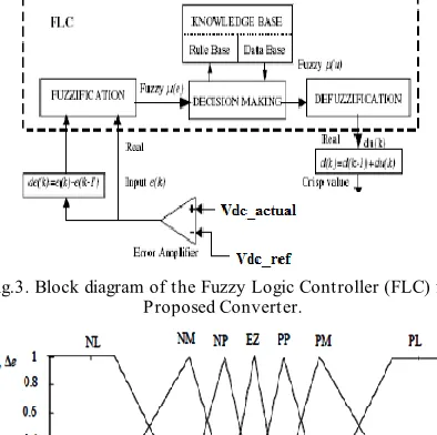
The basic scheme of a fuzzy logic controller is shown in Fig .3. and consists of four principal components such as: a fuzzy fication interface, which converts input data into suitable linguistic values; a knowledge base, which consists of a data base with the necessary linguistic definitions and the control rule set; a decision-making logic which, simulating a human decision process, infer the fuzzy control action from the knowledge of the control rules and linguistic variable definitions; a de-fuzzification interface which yields non fuzzy control action from an inferred fuzzy control action [10].
Fig.3. Block diagram of the Fuzzy Logic Controller (FLC) for Proposed Converter.
Fig.4. Membership functions for Input, Change in input, Output.
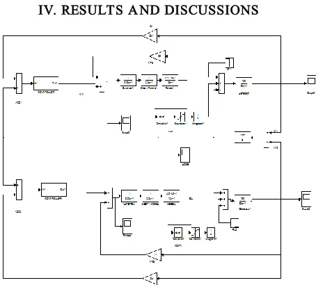
IV. RESULTS A ND DISCUSSIONS
Fig 5 Matlab/Simulink circuit for proposed system in linear zed model of an interconnected with fuzzy controller.
Fig.6 output wave form of the changing Deviation in frequency of area-1 in conventional method.
Fih.7 output wave form of the changing Deviation in frequency of area-2 in conventional method
Fig 8 output wave of the changing Deviation in tie-line power flow in conventional method.
Fig .9 output wave form of the changing in power output of Generator in area-1 when load is change.
Fig .10 output wave form of the changing in power output of Generator in area-2 when load is change.
Fig 11 output wave of the changing in power output of Generator in area-1 when load is change with fuzzy controller.
Fig.12. output wave of the changing in power output of Generator in area-2 when load is change with fuzzy controller.
V. CONCLUSION
control areas and inter-area tie-line power flow. From the simulation studies it is revealed that the SMES-TCPS combination of fuzzy controller can be effectively controlled frequency deviation and minimizing a quadratic performance index.
REFERENCES
[1] P. Kundur, Power System Stability and Control, McGraw HillInc. ,NewYork, 1994.
[2] Olle. L.Elegerd, Electric Energy systems Theory-Anintroduction Second Edition Tata McGraw-Hill Education Private Ltd. NewDelhi ,1983.
[3] Elgerd, O.I., and Fosha, C.: Optimum megawatt frequency control of multi-area electric energy systems, IEEE Trans. Power Appar. Syst.,, pp. 556-563,1 97 0. [4] Cohn, N.: Techniques for improving the control of bulk power transfers on interconnected systems , IEEE Trans. Power Appar. Syst., pp. 2409- 2419,197 1. [5] Miniesy, S.M., and Bohn, E.V.: Two level control of interconnected power plants, IEEE Trans. Power Appar. Syst.,pp. 2742 -2748,1971, 90, (6) [6] Hiyama, T.: Design of decentralized load frequency regulators for interconnected power systems, IEE Proc., Gener. Transm .Distrib., 1982.
[7] Rajesh Joseph Abraham, D Das, Amit Patra, ” Automatic generation control of an interconnected hydrothermal power system considering superconducting magnetic energy storage”, Electrical Power and Energy systems, Vol. 29, pp- 571-579, 2007 [8] Desire Championship, Somali Anwar, “Interaction between phase shifting transformers installed in the tie-linesof interconnected power systems and automatic frequency controllers”, Electrical Power Systems, Vol.33,pp-1351-1360,2001.
[9] R J Abraham, D Das, A Patra. ” Effect of TCPS on oscillations in tie-power and area frequencies in an interconnected hydrothermal power system.”, IET Generation, Transmission & Distribution, Vol. 1, pp. 632-639,2007.
[10] Rajesh Joseph Abraham, D Das, Amit Patra, “AGC study of a hydrothermal system with SMES and TCPS”, European Transactions on Electrical Power, Vol.19, pp. 487-498,2009.
[11] K.R.Sudha, R. Vijaya Santhi, “ Load Frequency Control of an interconnected Re heater thermal system using Type-2 fuzzy system including SMES units”,Electrical Power and energy systems, vol. 43, pp. 1383-1392,2012.
[12] Tripathy S C, Balasubramanian R, Chandramohanan Nair P S, “Effect of superconducting magnetic energy storage on automatic generation control considering governor deadband and bolier dynamics”, IEEE Trans. Power Systems , Vol.7, pp- 1266-1273,1992.
[13] Rajesh Joseph Abraham, Automatic Generation