SRINIVASAN, HARSHAD. Automated Model Processing and Localization of Additively Manufactured Parts for Finish Machining (Under the Direction of Dr Ola L. A. Harrysson and Dr Richard A. Wysk)
© Copyright 2016 by Harshad Srinivasan
by
Harshad Srinivasan
A dissertation submitted to the Graduate Faculty of North Carolina State University
in partial fulfillment of the requirements for the degree of
Doctor of Philosophy
Industrial and Systems Engineering
Raleigh, North Carolina 2016
APPROVED BY:
_______________________________ _______________________________
Dr Ola L. A. Harrysson Dr Richard A. Wysk
Committee Chair
_______________________________ _______________________________
DEDICATION
BIOGRAPHY
Harshad Srinivasan was born in Chennai (Madras), Tamil Nadu, India. He earned his
Bachelors in Technology in (B.Tech) in Instrumentation and Control Engineering at the
National Institute of Technology, Tiruchirappalli (Trichy) in 2009. He attended graduate
school at North Carolina State University, where he earned a Masters (MS) in Mechanical
Engineering with a focus on Mechatronics and Control Systems in 2011. Subsequent to
this he enrolled in the doctoral program at Industrial and Systems Engineering at NCSU,
ACKNOWLEDGMENTS
This work would not have been possible without the support of my family, friends
and colleagues. I would like especially thank my parents, Subhashini and V.R. Srinivasan,
who taught me the joys of learning and constantly encouraged and supported me through
this journey. I could not have gotten through this without Divya, my fiancé, who has
always been there to hold me up through the bad times and share in every moment of
joy.
I would like to express my gratitude to my advisor Dr. Ola Harrysson, and Dr Richard
Wysk for supporting my work and for giving me this opportunity. I would also like to thank
them and for their patience and for their guidance as I developed as a researcher. I would
like to thank Dr Ron Aman, Dr. Tim Horn, Dr. Harvey West and many others for all the
conversations, discussions, insights and help. Finally, I have to acknowledge the enormous
support I have received from my colleagues - the students and staff of CAMAL, NCSU;
they do amazing things every day.
This work would not have been possible without the support of the National Science
TABLE OF CONTENTS
1.
INTRODUCTION ... 11.1 Background ... 1
1.1.1 Additive manufacturing: ... 1
1.1.2 Hybrid manufacturing ... 3
1.1.3 CNC-RP ... 5
1.1.4 The DASH Approach ... 7
1.2 Motivation ... 8
1.2.1 File formats and digital representation ... 8
1.2.2 Automatic generation of machining allowances ... 8
1.2.3 Registration of sensor data... 9
1.2.4 Automatic generation of machining offsets ... 10
1.2.5 Other challenges that must be addressed by DASH ... 10
1.3 Summary and overview of dissertation structure ... 11
1.4 Chapter Bibliography ... 13
2.
LITERATURE REVIEW ... 162.1 Rapid Prototyping and Additive Manufacturing ... 16
2.1.1 Vat Polymerization ... 16
2.1.2 Binder Jetting ... 17
2.1.3 Powder Bed Fusion ... 17
2.1.4 Material Jetting ... 18
2.1.5 Material extrusion ... 18
2.1.6 Directed energy deposition ... 19
2.1.7 Sheet lamination ... 19
2.2 Additive manufacturing of metals... 20
2.2.2 Binder jetting processes... 24
2.2.3 Directed energy processes ... 27
2.2.4 Laminated object manufacturing ... 29
2.3 Indirect manufacture of metal parts by additive manufacturing ... 29
2.3.1 Additive manufacture of patterns for investment casting ... 30
2.3.2 Direct production of molds using additive manufacturing ... 31
2.4 Hybrid manufacturing ... 31
2.4.1 Hybrid material deposition / subtraction in CNC machines ... 32
2.4.2 Hybrid manufacturing by with other additive processes ... 36
2.4.3 Hybrid manufacturing by stacking of machined sections ... 36
2.5 Automatic workpiece sensing and 3D Scanning ... 37
2.6 Chapter Bibliography ... 41
3.
AMF FILE FORMAT WITH EXTENSIONS FOR GD&T ... 583.1 Background ... 58
3.1.1 File formats and their role in manufacturing ... 58
3.1.2 The AMF format ... 62
3.1.3 Features and Tolerances ... 66
3.2 Literature Review ... 67
3.2.1 Analysis of requirements ... 67
3.2.2 Approaches toward the solution and allied works ... 71
3.3 Synthesis of requirements ... 73
3.4 Proposed structure of Feature and Tolerance extensions to AMF ... 75
3.4.1 Feature designation ... 76
3.4.2 Feature Properties ... 78
3.4.3 Tolerance information ... 79
3.4.4 Nominal size... 83
3.4.5 Elements added to the AMF Specification ... 84
3.6 Observations ... 86
3.6.1 Future developments ... 88
3.7 Conclusions ... 90
3.8 Chapter Bibliography ... 92
4.
AUTOMATIC MESH OFFSET FOR THE GENERATION OF MACHINING ALLOWANCES ... 964.1 Background and Motivation ... 96
4.2 Literature review ... 98
4.2.1 Machining allowance by mesh offset ... 98
4.2.2 Other approaches to machining allowance in Hybrid systems ... 101
4.3 Problem description ... 102
4.4 Methodology ... 103
4.4.1 Procedure for computing vertex displacement vector ... 105
4.4.2 Procedure for detecting and filling edges ... 107
4.4.3 Implementation ... 109
4.5 Observations, future work, and conclusions ... 113
4.6 Chapter Bibliography ... 115
5.
AUTOMATIC REGISTRATION OF SCAN DATA TO MACHINE COORDINATE SYSTEM ... 1165.1 Background ... 116
5.1.1 Part localization ... 116
5.1.2 Current in-machine sensing systems ... 118
5.1.3 Three dimensional scanning ... 119
5.2 Literature Review ... 120
5.2.1 Scan matching systems ... 120
5.2.2 Registration of point cloud data to a defined coordinate system ... 121
5.2.3 Automatic estimation of scanner pose ... 122
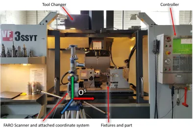
5.3 Description of setup ... 124
5.3.1 CNC machining station ... 125
5.3.2 3D Scanning systems ... 126
5.4 Approach ... 127
5.5 Per-Scan Registration ... 130
5.5.1 Fiducial Features ... 130
5.5.2 Registration algorithm ... 132
5.5.3 Experimental design ... 135
5.5.4 Results ... 137
5.6 Registration through estimation of fixed scanner pose ... 138
5.6.1 Observations from Per-Scan Registration system ... 138
5.6.2 Chuck geometry and datums ... 140
5.6.3 Registration algorithm ... 142
5.6.4 RANSAC Implementation ... 144
5.6.5 Procedure for Chuck Pose detection ... 146
5.6.6 Experimental design ... 150
5.6.7 Results and observations ... 156
5.7 Conclusions and future work ... 157
5.7.1 Future work ... 158
5.8 Chapter Bibliography ... 159
6.
AUTOMATIC FEATURE-BASED LOCALIZATION ... 1626.1 Background and Motivation ... 162
6.2 Literature review ... 163
6.2.1 Conclusions ... 165
6.3 Description of problem ... 165
6.4 Approach ... 167
6.4.1 Preparation of data ... 169
6.4.3 Optimization ... 174
6.4.4 Overall localization approach ... 177
6.5 Example ... 179
6.6 Observations, conclusions and future work ... 181
6.7 Chapter Bibliography ... 183
7.
SOFTWARE SYSTEMS ... 1857.1 AMFCreator ... 185
7.1.1 AMFCreator UI ... 185
7.1.2 Creating an AMF File ... 186
7.1.3 Creation and management of features ... 188
7.1.4 Triangle selection ... 190
7.1.5 Volume management ... 192
7.1.6 Computation of feature parameters ... 193
7.1.7 Addition of machining allowances ... 194
7.1.8 Creation of sacrificial support geometry ... 195
7.2 SCANUI ... 198
7.2.1 Scan management ... 199
7.2.2 Interface with FARO scanner ... 201
7.2.3 Interface with CNC Machine ... 203
7.2.4 Registration ... 204
7.2.5 Localization ... 207
7.3 Conclusions ... 211
7.4 Chapter Bibliography ... 212
LIST OF TABLES
Table 2.1: Parameters for some direct-metal powder-bed systems ... 26
Table 3.1: AMF-TOL Elements. ... 84
Table 5.1: Experimental results. XM etc refer to measured (true) coordinates while XL etc refer to the coordinates as located by the scan based localization system. All units are in mm ... 138
Table 5.2: Mean system performance ... 138
Table 5.3: Parameters of test system ... 156
LIST OF FIGURES
Figure 1.1: CNC-RP process. (a) shows CNC-RP setup (b1-b4) show creation of part and (b5-b6) show creation and removal of supports. Reproduced
with permission from [23]. ... 6
Figure 1.2: The DASH process sequence. ... 7
Figure 2.1 : Tree of Metal AM processes ... 21
Figure 2.2 : EOS M280 SLM system. Installed at CAMAL, North Carolina State University... 23
Figure 2.3: Concept Laser M2 Systems, Installed at Lawrence Livermore National Labs ... 23
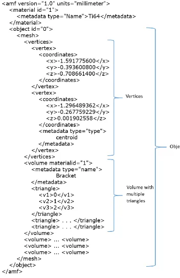
Figure 3.1: Core structure of the AMF document – showing geometry, material specification and metadata ... 65
Figure 3.2: AMF triangle, designated as a part of a feature with id ‘2’ ... 76
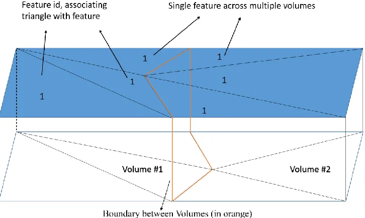
Figure 3.3: Features by assigning feature id to triangles. Also shown is the designation of a single feature across multiple volumes ... 77
Figure 3.4: XML of AMF with <features>, <feature>, id and feature information. Extensions to AMF are shown in Red ... 78
Figure 3.5: Basic Anatomy of a feature control frame per ASME Y14.5 2009 ... 79
Figure 3.6: Interpretation of tolerance zone from <maximum> and <minimum> tags. Top showing interpretation if both tags are present, bottom showing interpretation if <minimum> is omitted ... 81
Figure 3.7: Cylinder feature showing callout examples ... 82
Figure 3.8: UML of AMF-TOL. Extensions to AMF standard highlighted in Red ... 85
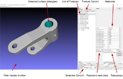
Figure 3.9: AMF Creator software showing ability to manipulate AMF-TOL files ... 86
Figure 4.1: Projection of displacement vector onto incident triangle normals... 99
Figure 4.2: Scheme for displacement of vertices presented by Qu and Stucker ... 100
Figure 4.3: Offset with multiple features ... 102
Figure 4.5: Machining allowance as a volume in the AMF object. (a) shows an AMF file with a feature highlighted, (b) shows the machining allowance as a closed volume, and (c) depicts the machining allowance together
with the original file ... 105
Figure 4.6: Effect of optimization approach ... 107
Figure 4.7: Hexagonal patch of triangles. Inside edges are shaded blue while outside edges are orange. Vertices are labeled with lower case letters and triangles with integers ... 109
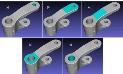
Figure 4.8: Five features in an example ‘Bracket’ part. Images (a) and (e) show hole features, while images (b), (c) and (d) show planes ... 110
Figure 4.9: Allowance added to features highlighted in Figure 4.8 ... 110
Figure 4.10: GE Bracket part. Features are highlighted in different colors ... 111
Figure 4.11: Machining allowance in GE Bracket part. ... 112
Figure 4.12: Machining allowance – blend between features. The black arrow shows the vertex displacement vector computed, to satisfy the two allowance requirements ... 112
Figure 5.1: HAAS VF3SSYT machining center. FARO Arm and associated coordinate system OS, Controller, Tool Changer are shown... 124
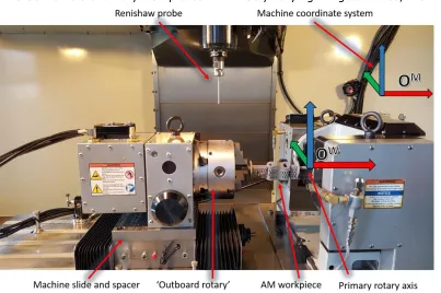
Figure 5.2: CNC Machine workspace. Shown are the right and left rotary systems with a workpiece held between them. The machine coordinate system is OM and OW is the work offset coordinate system attached to the rotary. The Renishaw probe is also shown. ... 125
Figure 5.3: Setup with NextEngine HD mounted in CNC machine ... 126
Figure 5.4: Coordinate system transform sequence ... 129
Figure 5.5: Experimental setup for per-scan registration system ... 131
Figure 5.6: Parts with Fiducial features labeled FB and FA. The fiducial feature surfaces are highlighted in Green ... 131
Figure 5.8: Per-Scan registration algorithm flowchart ... 134
Figure 5.9: Test workpiece. Image on right shows shims to simulate misalignment as well as Renishaw probe, used to measure workpiece test surfaces. .... 135
Figure 5.10: Combined point cloud ... 135
Figure 5.11: Test workpiece with reference surfaces highlighted in green. The coordinate system OP is attached to and constructed from the reference surfaces ... 136
Figure 5.12: Sequence of steps used to create a combined model of the test workpiece and to extract its true position in the CNC machine ... 137
Figure 5.13: Effect of fiducial feature location and orientation error. The ‘FE’ and ‘WE’ superscripts refer to a fiducial feature location error and workspace coordinate system error. ... 139
Figure 5.14: Chuck and axes ... 140
Figure 5.15: Chuck datums. The Chuck Body Cylinder is the primary Datum, colored Red; The Chuck Face is the secondary datum, in green; Jaw #1 Face is tertiary datum, colored blue. Jaws #2 and #3 are hidden, for clarity ... 141
Figure 5.16: Algorithm for chuck pose extractions ... 147
Figure 5.17: Example scan of chuck with 1.07 million points. ... 148
Figure 5.18: Rejection of ‘bad’ regions. Regions circled in white represent regions on the datum surfaces where points were rejected by the RANSAC system... 149
Figure 5.19: Extracted Datums. Chuck Body Cylinder in Red, Chuck Face in Green and Jaw in Blue. ... 149
Figure 5.20: Procedure for measuring the accuracy with which a chuck is located. True axis and Expected planes are shown in green, the measured axis and planes as produced are shown in orange ... 150
Figure 5.21: FARO Edge with Mazak CNC machine and Chuck ... 152
Figure 5.22: Chuck and Jaws; Scanned at 0, 60 and 240 degrees ... 153
Figure 5.24: Combined model of Jaw #2, Registered to the chuck coordinate
system... 154
Figure 5.25: Fitting of parallel planes to Jaw in Geomagic Qualify 2013 ... 155
Figure 6.1: Depiction of localization problem. Blue dots depict the 3D scanned measurements of the workpiece as built and as mounted. The arrows attached to each point show the normal direction, oriented ‘outwards’. The nominal part pose is shown in Orange, the Optimal part pose is shown in Green and an infeasible pose is shown dashed in purple. Coordinate system shown as per convention – Blue is Z axis and X is in Red. ... 167
Figure 6.2: Down-sampling. From left to right we have the initial cloud, the grid and the final selected points. The output points are selected from the grid boxes with more than a threshold number of points (3, in this case), shown in Green. Red boxes were rejected and white boxes were never constructed as they contain no points. ... 170
Figure 6.3: Projection based correspondence estimation. The dashed lines are rays, oriented along the point normal, from the point to the nearest triangle
... 171
Figure 6.4: Ray-triangle intersection. Projection vectors are collinear with the point normal. The projected points lie on the triangle plane, either inside or outside the triangle. ... 172
Figure 6.5: Rejected correspondences. Point (a) is rejected as its angle is too ‘shallow’. (b) is rejected as it lies further away than a specified distance from the triangle (c) is rejected as its normal is not aligned with the
triangle ... 173
Figure 6.6: Point-triangle correspondence computation. Each set of braces represents a (nested) loop. ... 174
Figure 6.7: Error function in solid blue. The Cutoff is the intercept on the Distance Axis, representing a triangle point distance equal to the desired allowance. The dashed blue line represents the error function without the cutoff. ... 176
Figure 6.8: Error function logic. The horizontal axis is point-surface distance and
Figure 6.9: Best-Fit system UI ... 179
Figure 6.10: Fit steps. (a) shows initial displacement, (b), (c) and (d) show the alignment after 1, 2 and 3 iterations respectively ... 180
Figure 6.11: Fit statistics ... 181
Figure 7.1: AMFCreator software. Major sections are labeled ... 186
Figure 7.2: Creating and selecting an object ... 187
Figure 7.3: Tasselated geometry imported as volume ... 188
Figure 7.4: Adding features ... 188
Figure 7.5: Feature controls ... 189
Figure 7.6: Selection parameter controls ... 190
Figure 7.7: Effect of selection angle threshold. Same triangle clicked in all cases. ... 191
Figure 7.8: Volume management. Seen is volume list with selected volume. Selected volume highlighted in the display window. ... 192
Figure 7.9: Volume visibility dialog box. ... 192
Figure 7.10: Cylinder feature and extracted parameters. Parameters displayed as metadata ... 194
Figure 7.11: Addition of machining allowances. Resulting allowance highlighted in display window. ... 194
Figure 7.12: Support geometry generation stages. (a) is initial geometry (b) transformation to manufacturing position (c) support struts (d) fixturing features ... 196
Figure 7.13: Support Generation UI ... 197
Figure 7.14: SCANUI interface elements ... 198
Figure 7.15: Point cloud on right created by clipping the point cloud on the left ... 199
Figure 7.16: Down-sampling of scans ... 200
Figure 7.17: Faro scanner control options ... 201
Figure 7.18: Meshing of point cloud ... 201
Figure 7.20: Serial port controls ... 204
Figure 7.21: Registration parameters ... 205
Figure 7.22: Stitching scans together. Shown are the combined extracted datums and four scans to be stitched together. ... 206
Figure 7.23: Combined, registered scan ... 207
Figure 7.24: Localization controls ... 208
Figure 7.25: Model with selected features highlighted ... 209
Figure 7.26: Features to use ... 209
Chapter 1
INTRODUCTION
This chapter presents a brief introduction to additive and hybrid manufacturing, their
advantages, shortcomings and associated challenges. The additive manufacture of metals
is briefly explored and hybrid manufacturing, as a possible solution to the shortcomings
of direct additive metal fabrication, is introduced. Specifically, a hybrid manufacturing
system is described in which existing additive and subtractive systems are tied together
using software (Digital Additive and Subtractive Hybrid manufacturing or DASH system).
The challenges associated with this system are briefly explored. Four specific requirements
of the DASH process are identified and approaches to address these challenges are
outlined. Finally, the structure of the rest of this dissertation is provided.
1.1 Background
1.1.1Additive manufacturing:
Additive manufacturing (AM) is defined by the American Society for Testing and
Materials as “A process of joining materials to make objects from 3D model data, usually
layer upon layer, as opposed to subtractive manufacturing methodologies” [1]. The origins
of modern Additive Manufacturing technology can be traced to the rapid prototyping (RP)
systems first developed in the 1980s. Unlike RP systems, that have been are used to
produce prototypes for fit testing and visual evaluation, AM systems are focused on the
creation of functional net-shape or near-net-shape parts.
Similar to rapid prototyping, additive manufacturing involves the production of parts
layer by layer, with each layer forming a cross section of the part. To form a layer, material
chemical or mechanical. This process – the production of parts by the addition of material,
as opposed to material removal, deformation or solidification as in traditional
manufacturing, gives additive manufacturing its name.
In general, AM systems do not require tooling or significant process planning. The
geometric constraints imposed by additive manufacturing methods are far less stringent
than traditional manufacturing methods- allowing for internal cooling channels,
functionally graded structures and non-stochastic mesh structures [2] [3] [4]. Several
additive manufacturing methods also permit the use of materials that are difficult to
process with traditional manufacturing methods such as superalloys and amorphous
metals [5] [6]. Several studies have also indicated that additive manufacturing systems
feature lower levels of material wastage than traditional manufacturing, that is - they
feature a high 'buy-to-fly' ratio. This measure is one that has grown from the aerospace
industry, where it is not unusual to machine away as much as 80% of the material from
raw stock.
AM systems also suffer from several drawbacks. The processing time per part with
additive manufacturing is usually far longer than in traditional methods. The raw materials
used for AM systems also tend to be more expensive and difficult to handle than the
equivalent raw stock used by traditional manufacturing systems [7]. Historically, additive
processes could not match the material properties (density, porosity, crystal structure) of
parts produced by traditional means, e.g. forgings or castings, nor the accuracy of CNC
machining. However significant progress in addressing material deficiencies has been
made in recent years, to the extent that additively produced metal parts now regularly
exceed the material performance of those made by traditional means [8] [9].
These factors render additive manufacturing well suited for the production of high
performance parts which feature novel materials and geometries, and/or parts for which
medical devices that are customized to the patient, aerospace parts where performance
is paramount and legacy replacement parts for which tooling would otherwise have to be
re-created. These attributes have sparked significant interest in using additive
manufacturing in the aerospace, automobile, medical device, and tool and die industries.
The market for Additive manufacturing in 2012 was estimated at $2.204 billion with a
growth rate of 28.6% [10] with additive manufacturing of metals estimated at a $24.9
million and a growth rate of 38.3%. More recently, General Electric has earmarked $3.5
Billion for investment into additive manufacturing, indicating strong interest in additive
manufacturing from major corporations [11] [12].
The additive manufacture of metal parts holds special interest [13] as metals and
metal alloys are among the most important classes of engineering material in use today.
However, direct metal-AM parts possess surfaces that can be distorted by internal
stresses, witness marks from the removal of support structures and high surface
roughness [2], [14], [15]. Parts produced by indirect metal AM methods- either by
investment casting with additively produced patterns or by casting in additively produced
molds require the removal of runners, gate and vents and have to be finish machined in
order to achieve required dimensional accuracy. This is in addition to the “stair-stepping”
inherent in layer based manufacturing. Therefore, as with traditionally produced
near-net-shape parts; subtractive finish machining is required before additively produced parts can
be utilized. This process – the production of near-net-shape parts by additive means
followed by subtractive finishing using CNC machining comes under the ambit of the term
'Hybrid Manufacturing'.
1.1.2Hybrid manufacturing
Hybrid manufacturing is a term that covers systems that combine more than one
we restrict the use of the term 'hybrid manufacturing' to refer to the finish machining of
parts produced by additive manufacturing.
In order to meet required form and dimensional tolerances, near-net-shape parts
require finish machining. Parts are finished by mounting them in a CNC machining station,
which is then used to machine away excess material and create critical mating and contact
surfaces etc. The near-net-shape part is designed with 'overgrown surfaces' to ensure
enough excess material is present for the successful creation of these critical surfaces.
Adopting this strategy with additively produced parts incurs several of the same drawbacks
that additive manufacturing seeks to avoid. Parts to be finished must be precisely located
in the CNC machine coordinate system. This is performed by either 1) mounting parts in
a series of specially designed fixtures, or 2) by manual positioning and offsetting the part
using probes and indicators, an operation that takes considerable time and skill. Carefully
designed and optimized machining tool-paths must also be developed to produce parts in
this manner. These strategies run counter to the use-case for AM- where low fixed costs
process and production engineering are followed by short lead times.
Several attempts have been made to address this challenge by integrating the
additive and subtractive sub-systems into a single machine such as the Matsuura Lumex
advance-25 [17]. The subtractive system is used to machine the periphery and/or face of
each layer, as they are created. This approach, however, requires that a complete system
be developed and deployed, representing significant capital costs. Other systems attempt
to simplify and reduce costs by retrofitting existing CNC systems with additive capability,
for example the HLM system [18] developed at the Indian Institute of Technology (IIT),
Bombay and the laser cladding system developed by Hybrid Manufacturing Technologies
[19]. Approaches of this nature appear incapable of generating many of the more complex
In order to circumvent these limitations while maintaining the best attributes of both
additive and subtractive manufacturing, it is desirable to utilize existing, proven, additive
and subtractive machines and tie them together using intelligent part design, sensing and
software. Such a system would minimize the need for manual intervention in fixture design
and tool-path planning for the finish machining. Such a system is the goal of the DASH
system.
1.1.3CNC-RP
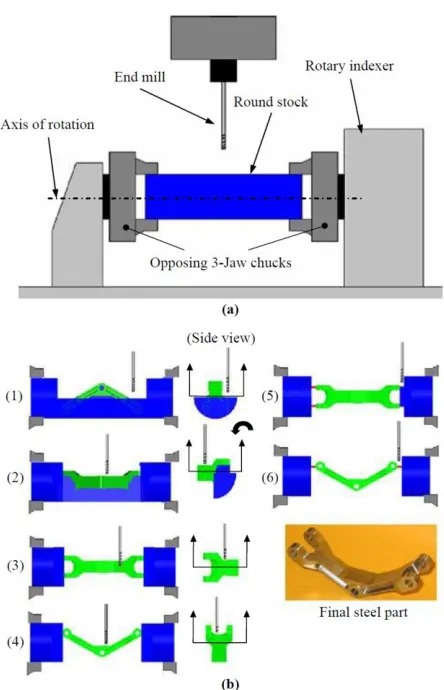
CNC-RP is a CNC-machining-based rapid prototyping system [21]. In CNC-RP,
bar-stock is held between centers (in a 3 jaw chuck or similar system) in the CNC machining
station such that it can be rotated (indexed) and machined from multiple orientations. At
each orientation, the CNC machine is used to create all accessible part surfaces. This is
performed by “island milling” - removing material layer by layer. Once all surfaces
accessible at a particular orientation have been created, the bar stock is rotated to the
next computed orientation and the process is repeated, creating those surfaces now
accessible. This is repeated until all part surfaces have been created. Given a target part
file, the CNC-RP software system computes the minimum diameter needed for the bar
stock, the set of angles from which all part surfaces are accessible ('visible') and machining
tool-paths for each angle. The tool-paths are generated by a commercial CAM system,
integrated into the CNC-RP software.
This approach reduces tool-path generation to a set of '2 ½' axis problems, for which
existing automatic tool path generators in commercial CAM software are sufficient. The
CNC-RP software also adds features to the part, in order to support it through the
machining operation(s), as the stock is machined away. The software designs these
supports to hold the part to within the minimum allowable deflection. After the process is
completed the supports are manually removed and any remaining witness marks are
rotation. Extensions, to compute the optimal axis of rotation as well, have since been
studied [22]. Figure 1.1 illustrates the CNC-RP Process.
Figure 1.1: CNC-RP process. (a) shows CNC-RP setup (b1-b4) show creation of part and (b5-b6) show creation and removal of supports.
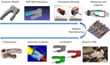
1.1.4The DASH Approach
The Digital Additive Subtractive Hybrid (DASH) system extends CNC-RP to the
automatic finishing of additively manufactured parts. In DASH, (sacrificial) support
features are automatically added to the part before production in an existing additive
machine. In addition, prior to additive manufacture, the part is 'overgrown' (allowances
are added to the part) in order to compensate for inaccuracy in the additive and
subtractive systems. The sacrificial support features are used to mount the part in the
CNC machine, between centers. Subsequent to this, a measurement and sensing system
is used to determine the shape, form and position of the material actually present in the
CNC machine. Finally, A CNC-RP-like software system is used to automatically generate
the set of angles for machining visibility and the finishing tool-paths at each indexed angle.
After the finish machining is completed, the sacrificial features are removed, either
manually or by the CNC machine, and any remaining witness marks manually finished.
Figure 1.2 shows the DASH process sequence.
This approach requires the development of several new technologies and
methodologies. The necessity for these methodologies, forms the motivation for this
dissertation.
1.2 Motivation
The DASH process provides a path towards the automatic production of parts which
feature both the materials and geometries enabled by additive manufacturing as well as
the accurate surfaces and features required for many applications. However, there are
several challenges with DASH, which must be addressed before it can be utilized at a
commercial level. This dissertation is motivated by the need to address four specific
challenges.
1.2.1File formats and digital representation
The DASH process involves the intelligent combination of additive and subtractive
manufacturing as well as in-process sensing together with several processing and planning
algorithms. In order to drive these systems, it is necessary to define a portable data format
that holds the required geometric, feature and tolerance information. Such a data format
will form the basis of information storage, retrieval and exchange between the various
modules that comprise the DASH system and ensure data portability as well as consistent
inputs to all systems. In addition, a proper data format will allow information exchange
with all potential stakeholders involved.
1.2.2Automatic generation of machining allowances
Finish machining involves the removal of material from a workpiece, in order to
produce the required part, to the required tolerances. In order to be successful, the
workpiece must have sufficient excess material such that all desired part surfaces may be
found within it. In order to achieve this condition, machining allowance must be added to
In DASH, this must be performed automatically and on a per-feature basis, prior to
additive manufacture. Therefore, a system for altering the nominal part geometry
automatically by adding additional material for machining allowances on a per feature
basis to a part model, is necessary.
1.2.3Registration of sensor data
Since the sacrificial support features used by the DASH process are produced by the
same additive process as the part, they feature similar rough, near-net-shape surfaces.
When these rough surfaces are used to clamp and locate the part in a fixture, the part
location becomes uncertain.
Additionally, in practice, those AM support structures which can easily be removed
are manually broken off before mounting in the CNC machine. Any tool-path designed to
machine away the maximum possible volume that these support structures may occupy
will spend a significant amount of time 'cutting air'.
The integration of a workpiece measurement and sensing system into the CNC
machine is a possible means to address these challenges. Such a system can be used to
generate a model of the part as-built and as it is mounted in the CNC machine. This model
may then be used to efficiently harvest the desired part from the material actually
present in the CNC machine.
Optical systems capable of capturing three dimensional data appear to be best suited
for the task in-machine workpiece sensing and workpiece model generation. These systems,
sometimes referred to using the term ’3D scanning’ consist of a family of technologies
that can capture three dimensional data of surfaces present in their field of view. 3D
scanning systems generate dense data – up to millions of points per scan. This enables
the detection of features and geometries that cannot be adequately detected by touch
However, scan data is produced in a frame of reference internal to the scanner. In
order to drive tool-path creation, this data must be transformed to the CNC coordinate
frame. Traditional methods for addressing this are impractical, inflexible and in many
cases cost-prohibitive.
In order to address this, a method for automatically transforming 3D scan data from
the scanner to machine coordinate systems is necessary.
1.2.4Automatic generation of machining offsets
Finally, it is necessary to compute offsets that compensate for the difference
between the nominal part model and the model of the workpiece material as built and as
it is mounted in the CNC machine. These offsets must move the part ‘into’ the material
present, such that there is sufficient material present ‘above’ each feature for its successful
production. This offset generation system must be fast and capable of accommodating
arbitrary geometries.
1.2.5Other challenges that must be addressed by DASH
In addition to the four challenges highlighted in sections 1.2.1 – 1.2.4, that are the
focus of this dissertation, there are several other challenges that must be addressed in
order for the successful manufacture of parts via the DASH process.
1.2.5.1 Selection of machining axis and strategy
Due to the limitations of tool access in CNC machining, only surfaces with a clear
line of sight can be finish-machined. This limits the ability of DASH to finish-machine part
surfaces when inaccessible geometries are present in the part. However, in most
'engineering' parts, the critical surface are external mating surfaces and finishing of
non-critical surfaces is secondary to accurately producing these, a task DASH is well suited for.
In order to successfully produce a part, it is important to ensure that all critical part
tolerance can be machined using an appropriate strategy and that mating surfaces are
not marred by the attachment of sacrificial fixturing features. This requires careful
selection of the axis of rotation and consequently, the selection of the attachment sites of
for the sacrificial supports.
For certain parts, it may be impossible to satisfy all the competing objectives
simultaneously. In these cases, it becomes necessary to select the most critical surfaces
and prioritize them for proper finish machining over less critical surfaces
1.2.5.2Part and tool deflection under machining forces:
In the DASH approach (as in CNC-RP), the part is held between centers at opposite
ends, a configuration significantly less rigid than a part held in a traditional fixture. This
results in both static part deflection under machining forces and dynamic deflection
(vibration). In addition, the tools required by these machining strategies tend to be long
and feature small diameter-length aspect ratios. When machining tough materials, this
causes significant tool deflection and chatter, resulting in incomplete material removal and
poor surface and dimensional quality. These effects must be understood and accounted
for.
1.3 Summary and overview of dissertation structure
In this chapter, brief introductions to additive manufacturing, hybrid manufacturing
and the DASH system were presented. Four specific challenges that must be addressed in
order for the DASH system to meet its requirements were identified.
Chapter 2 presents a review of the literature and current state of additive
manufacturing and hybrid manufacturing. Chapter 3 describes the development of a file
format to address the needs of the DASH process by extending the AMF specification to
include features and tolerances. Chapter 4 describes a methodology for the automatic,
AMF file which includes demarcated features. Chapter 5 describes a methodology by which
the problem of registering scan data to the CNC machine work coordinate system is
addressed. This is performed by automatically detecting and measuring fiducial features
in the CNC machine workspace. These measurements are used to transform scan data in
order to create a model of the workpiece as built and as it is mounted in the CNC machine.
Chapter 6 presents a system for the automated computation of offsets to compensate for
deviations between the nominal part geometry and the scanned workpiece model. Chapter
7 contains descriptions and examples of the software systems that incorporate these
methodologies and integrate them into the unified DASH manufacturing system. Finally,
Chapter 8 contains a discussion and conclusion of the systems described and developed
in this dissertation, together with proposed avenues for future work.
Chapters 4 through 7 each contain an introduction to the problems they address, a
review of literature specifically connected with that problem, a description of the solution
approach, a section on testing and analysis and a conclusion section that includes
limitations, challenges and future work associated with each of these systems. In this way,
1.4 Chapter Bibliography
[1] A. Standard, “F2792. 2012. Standard Terminology for Additive Manufacturing Technologies,” ASTM F2792-10e1.
[2] I. Gibson, Additive manufacturing technologies: rapid prototyping to direct digital manufacturing. London ; New York: Springer, 2010.
[3] L. E. Murr, S. M. Gaytan, F. Medina, H. Lopez, E. Martinez, B. I. Machado, D. H. Hernandez, L. Martinez, M. I. Lopez, R. B. Wicker, and J. Bracke, “Next-generation biomedical implants using additive manufacturing of complex, cellular and functional mesh arrays,” Philos. Trans. R. Soc. Math. Phys. Eng. Sci., vol. 368, no. 1917, pp. 1999–2032, Apr. 2010.
[4] L.-E. Rännar, A. Glad, and C.-G. Gustafson, “Efficient cooling with tool inserts manufactured by electron beam melting,” Rapid Prototyp. J., vol. 13, no. 3, pp. 128– 135, Jun. 2007.
[5] L. E. Murr, S. M. Gaytan, D. A. Ramirez, E. Martinez, J. Hernandez, K. N. Amato, P. W. Shindo, F. R. Medina, and R. B. Wicker, “Metal Fabrication by Additive Manufacturing Using Laser and Electron Beam Melting Technologies,” J. Mater. Sci. Technol., vol. 28, no. 1, pp. 1–14, Jan. 2012.
[6] G. P. Dinda, A. K. Dasgupta, and J. Mazumder, “Laser aided direct metal deposition of Inconel 625 superalloy: Microstructural evolution and thermal stability,” Mater. Sci. Eng. A, vol. 509, no. 1–2, pp. 98–104, May 2009.
[7] C. K. Chua, K. F. Leong, and C. S. Lim, Rapid prototyping: principles and applications. World Scientific, 2010.
[8] E. C. Santos, M. Shiomi, K. Osakada, and T. Laoui, “Rapid manufacturing of metal components by laser forming,” Int. J. Mach. Tools Manuf., vol. 46, no. 12–13, pp. 1459–1468, Oct. 2006.
[9] L. E. Murr, E. V. Esquivel, S. A. Quinones, S. M. Gaytan, M. I. Lopez, E. Y. Martinez, F. Medina, D. H. Hernandez, E. Martinez, J. L. Martinez, S. W. Stafford, D. K. Brown, T. Hoppe, W. Meyers, U. Lindhe, and R. B. Wicker, “Microstructures and mechanical properties of electron beam-rapid manufactured Ti–6Al–4V biomedical prototypes compared to wrought Ti–6Al–4V,” Mater. Charact., vol. 60, no. 2, pp. 96–105, Feb. 2009.
[11] H. Smith, “3D Printing News and Trends: GE Aviation to grow better fuel nozzles using 3D Printing.” .
[12] B. P. Conner, G. P. Manogharan, A. N. Martof, L. M. Rodomsky, C. M. Rodomsky, D. C. Jordan, and J. W. Limperos, “Making sense of 3-D printing: Creating a map of additive manufacturing products and services,” Addit. Manuf.
[13] “Layers of Complexity: Making the Promises Possible for Additive Manufacturing of Metals,” JOM, pp. 1–14, Oct. 2014.
[14] M. B. Bauza, S. P. Moylan, R. M. Panas, S. C. Burke, H. E. Martz, J. S. Taylor, P. Alexander, R. H. Knebel, R. Bhogaraju, M. T. O’Connell, and others, “Study of accuracy of parts produced using additive manufacturing,” Lawrence Livermore National Laboratory (LLNL), Livermore, CA, 2014.
[15] G. D. Kim and Y. T. Oh, “A benchmark study on rapid prototyping processes and machines: quantitative comparisons of mechanical properties, accuracy, roughness, speed, and material cost,” Proc. Inst. Mech. Eng. Part B J. Eng. Manuf., vol. 222, no. 2, pp. 201–215, Oct. 2008.
[16] Z. Zhu, V. G. Dhokia, A. Nassehi, and S. T. Newman, “A review of hybrid manufacturing processes – state of the art and future perspectives,” Int. J. Comput. Integr. Manuf., vol. 26, no. 7, pp. 596–615, 2013.
[17] “Matsuura Machinery Corporation|LUMEX Avance-25.” [Online]. Available: http://www.matsuura.co.jp/english/contents/products/lumex.html. [Accessed: 11-Jun-2014].
[18] K. P. Karunakaran, S. Suryakumar, V. Pushpa, and S. Akula, “Low cost integration of additive and subtractive processes for hybrid layered manufacturing,” Robot. Comput.-Integr. Manuf., vol. 26, no. 5, pp. 490–499, Oct. 2010.
[19] “Hybrid Manufacturing Technologies | Technology,” Hybrid Manufacturing
Technologies. [Online]. Available:
http://www.hybridmanutech.com/technology.html. [Accessed: 14-Jun-2014].
[20] I. Kelbassa, T. Wohlers, and T. Caffrey, “Quo vadis, laser additive manufacturing?,” J. Laser Appl., vol. 24, no. 5, p. 050101, Nov. 2012.
[22] Y. Li and M. C. Frank, “Computing Axes of Rotation for Setup Planning Using Visibility of Polyhedral Computer-Aided Design Models,” J. Manuf. Sci. Eng., vol. 134, no. 4, pp. 041005–041005, Jul. 2012.
[23] Joseph E. Petrzelka and Matthew C. Frank, “Advanced process planning for subtractive rapid prototyping,” Rapid Prototyp. J., vol. 16, no. 3, pp. 216–224, Apr. 2010.
[24] D. R. McMurtry, “Contact-sensing probe,” 4155171, 22-May-1979.
Chapter 2
LITERATURE REVIEW
This chapter contains an overview of the literature pertinent to this dissertation.
Section 2.1 contains a very brief review of the history and classification of Rapid
Prototyping and Additive Manufacturing Technologies. Direct metal additive manufacturing
is a field of particular interest to this work, a review of the processes and research in this
field is presented in Section 2.2. Section 2.3 presents the developments and work in the
field of hybrid manufacturing. Finally, In-machine workpiece sensing and 3D scanning
technologies are reviewed in section 2.4. In addition to the information contained in this
chapter, chapters 4 through 8 contain reviews of the literature and state of the art directly
related to their specific research objectives.
2.1
Rapid Prototyping and Additive Manufacturing
The production of parts additively, layer by layer, was first described and patented
in the 1980s [1] by groups in several countries, including Japan, France and the USA. A
number of different approaches to rapid prototyping and additive manufacturing have
since been developed. These can be classified into categories based on the processes and
technologies involved, as in ASTM F2792 [2]:
2.1.1Vat Polymerization
Vat Polymerization [2] systems involve the selective curing of liquid polymer in a
vat, usually by optical means. After a part cross section (layer) has been created (cured),
the layer is re-coated with polymer resin and the process is repeated. The first Vat
Polymerization system was SLA ('Steriolithography Apparatus'), patented by Charles Hull
in 1984 [3] and marketed by 3D systems. This was also the first commercial, additive,
galvanically steered laser spot. Modern developments include the use of micro mirror
arrays (DLP technology) [4] [5] [6] to project light patterns,[4] micro scale lithography
[7] [8] [9] and more sophisticated resins [10] [11] [12].
2.1.2Binder Jetting
In Binder Jetting processes, layers are generated by selectively spraying a binder
onto a powder bed. The binder fuses the powder to form a solid layer. Once a layer is
created, the powder bed is lowered, re-coated with an even layer of powder and the
process is repeated to build up the object. The first binder jetting processes was '3D
printing', developed at MIT in 1989 [13] [14]]. Modern Binder Jetting processes can be
used to create plastics [4], composites [12] [15], ceramic [16], sand (for casting) [17]
[18] [19] [20] and metal parts [21] [22] [23]. This process is also capable of generating
full color parts, by using pigments along with the binder. Curing, infiltration and sintering
may be required after initial part production for the part to achieve its final strength and
surface characteristics [12] [21] [23].
2.1.3Powder Bed Fusion
Powder Bed Fusion processes function similarly to binder jetting in that solid layers
are generated by fusing powder together, in a powder bed. In powder bed fusion, however,
the binding is achieved by application of thermal (in the form of focused energy) rather
than chemical energy. The first process of this type was Selective Laser Sintering (SLS),
developed in the late 1980s by Drs. Joseph Beaman and Carl Deckard and marketed by
the DTM corporation [24] [25] [24] (since then acquired by 3D Systems). The thermal
energy may cause either sintering as in SLS or complete melting as in Direct Metal Laser
Sintering [26] (DMLS), Selective Laser Melting [27] (SLM) and Electron Beam Melting
(EBM) processes [27] [28] [29]. Powder bed fusion can be used to generate
powders) [4] [30] [31]. Lasers, focused light and Electron Beams have been used as
energy sources.
2.1.4Material Jetting
In material jetting processes, droplets of material are sprayed from a nozzle (or
series of nozzles) in order to build up layers. The jetting may be achieved by piezoelectric,
thermal or by jetting in an aerosol form [32] [33]. Materials can include polymers
(including photopolymers), waxes (for investment casting), ceramics [34] and metals [1]
[4] [35]. If a photopolymer is employed, an appropriate light source adjacent to the
deposition head is used as a source of energy for curing. The first such devices were
manufactured and marketed by Solidscape Inc. (then known as Sanders Prototype) in
1994 [1]. More recently, this method has been extended to the direct production of
functionally graded and multi-material parts [36], electronic components that include both
conductive and insulating elements [37] [38] and weld based production of metal parts
using droplets of molten metal [39] [40] [41] [42].
2.1.5Material extrusion
Material extrusion processes are among the most common solid free-form
fabrication systems in use today, representing the largest installed base [43]. In material
extrusion processes a continuous stream of material extruded from a nozzle is used to
build up part layers. The nozzle is moved relative to the build platform, in order to create
the layer geometry. The first material extrusion system, Fused Deposition Modeling (FDM)
was developed and patented by Scott Crump in 1989 [44]. FDM systems produce
thermoplastic parts by the extrusion of a stream of material heated to above its glass
transition temperature. Materials include a wide variety of engineering plastics such as
Nylon, ABS, PLA, Polycarbonate [45] and elastomers [46] [47]. Other materials that may
be processed by FDM style material extrusion include metals [48] and ceramics [49] [50]
fiber. Systems capable of extruding cement and high performance concrete [51] [52] [53],
bio-compatible materials [54] [55], food [56], and conductive elements [57] [58] have
also been developed.
2.1.6Directed energy deposition
Directed energy deposition processes are similar to material jetting and material
extrusion is some respects. In directed energy deposition systems, focused thermal
energy is used to bond (by fusion or surface sintering) materials to the substrate (prior
layers or the build platform) in order to build up layers. The material may consist of a
continuous wire feed or powder carried by an inert gas [59] [60] [61]. The thermal energy
may be supplied by laser [62], electron beam [63] or plasma arc [64]. The first powder
based directed energy deposition systems was the LENS process developed at Sandia Labs
and marketed by Optomec [1] [65] [66]. These systems are primarily used to produce
metal parts, including high performance aerospace alloys [67], and are often used for
mold and part repair and re-manufacture [68]. Materials can include functionally graded
parts, produced by varying the material composition during the build [69].
2.1.7Sheet lamination
Sheet lamination processes produce parts by fusing sheets of material one on top of
the other, forming a laminate. The cross section of the part (the layer shape) is cut out of
each sheet either after bonding (bond-then-form) or before bonding (form-then-bond) [1]
[4]. After production, the sections of the laminate not corresponding to the part are
broken off. The process of removing excess material may be assisted by the addition of a
hatch pattern in the excess material while the layer profile is also being created. The first
sheet lamination process, Laminated Object Manufacturing (LOM) can be credited to
Michael Feygin and Helisys Inc. (succeeded by Cubital Technologies) in 1985-86 [4] [70].
Sheets may be composed of metal [71], polymer, or paper [12] [72]. Cross sections may
sheets with a blade. Bonding may be achieved chemically, thermally or by ultrasonic
welding.
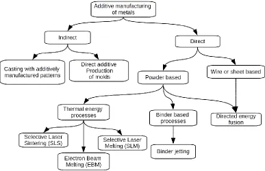
2.2 Additive manufacturing of metals
The focus of this dissertation is the development of an automated system for the
finish machining of near-net-shape parts. The proposed system can be used with nearly
any such process, including traditional methods such as forging and casting. However,
economic and performance considerations limit its utility to the finish machining of parts
produced using additive manufacturing. The objective of this section is to describe the
state-of-the-art in Metal additive manufacturing with a focus on commercially available
systems. The Process capabilities, limitations, materials and other characteristics will be
briefly discussed. This will help form a map of additive manufacturing processes that can
be used to ‘drive’ the proposed system. Processes are grouped by the ASTM classification
from section 2.1. The final section - Indirect manufacture of metal parts by additive
manufacturing - contains a brief review of indirect metal part production methods – metal
parts produced using additively produced patterns for investment casting and direct
additive mold production for sand casting. Figure 2.1 : Tree of Metal AM processes shows
2.2.1Powder bed fusion processes
The first metal capable powder bed fusion process was Selective Laser Sintering
(SLS) [24], [25], [73]. In selective laser sintering, one or more lasers are used to bind
powdered material by selectively raising the local temperature [74]. This causes power
particles to bind by one of several mechanisms – (i) Solid State Sintering , (ii) Chemically
Induced Binding, (iii) Liquid Phase Sintering, and (iv) Full Melting [29] [75]. When Full
Melting occurs, the process is generally referred to as Selective Laser Melting (SLM). SLS
was first used to produce metal parts via the Liquid Phase Sintering process in which
binding is achieved by melting thermoplastic. The thermoplastic is either mixed in with
the metal powders or metal powder particles are coated in thermoplastic [76]. After
processing in the SLS system, the part is removed and thermally treated to burn off the
thermoplastic and sinter the metal powders, forming a partially dense metal part and in
some cases infiltrated to provide improved performance and density part [16] [77] [78]
[79] [80].
Modern systems for the production of metal parts largely rely on the full melting and
direct bonding of power by higher power lasers. Examples include 3D System's Direct
Metal Printing (DMP) systems [81] [82], Renishaw's AM250 [83], SLM Solution's SLM
series [84], Concept Laser's Lasercusing systems [85] and the Direct Metal Laser Sintering
(DMLS) process by EOS GmbH [86].These systems directly process metal powders and
supply enough energy to either sinter or completely melt the functional metal powders
directly. It must be noted that many DMLS systems, despite the name, achieve full melting
[4] [87]]. Laser melting is considered superior to Laser sintering as it can be used to
produce parts with superior density and mechanical properties and requires less post
processing [88]. However, due to the high thermal gradients and considerable shrinkage
during the solid-liquid-solid transformation, significant internal stresses can arise,
potentially leading to distortions and cracks in the final part [89] [90] [91] [92]. This
necessitates the addition of support structures to hold the part in place against warping.
The removal of these support structures is laborious and time consuming. In addition, a
heat treatment process, such as hot iso-static pressing or annealing is required before the
part is removed from the build plate in order to prevent part distortion due to internal
stresses [1] [93] [94] [95].
The part is normally produced fused to the build platform. Separation from the
platform is performed by cutting the part off with a saw or by Wire-EDM. This must be
followed by removal of support structures and finish machining of surfaces and features
to specified critical tolerances or surface finish. The Matsuura Lumex 25 [96] is the
exception to this as it integrates both additive and subtractive subsystems into the same
volume. This allows additively produced layers to be finish machined as they are produced,
simplifying or completely eliminating the requirement for process planning and tooling for
Electron Beam Melting (EBM) by Arcam is a powder-bed-fusion process similar to
Selective Laser Melting. However, in EBM the thermal energy is provided by an electron
beam generated by a heated tungsten filament and collimated, focused and guided by
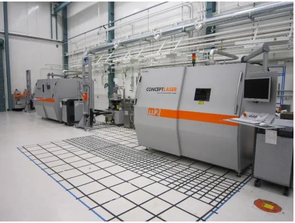
Figure 2.3: Concept Laser M2 Systems, Installed at Lawrence Livermore National Labs
magnetic fields. Full melting and near 100% part densities are achieved [28] [97]. The
use of an electron beam provides certain advantages including higher scan rates (up to
10,000 m/s) [28] [98], higher beam power and efficiency [88] and associated higher build
rates compared to laser based processes [99], reduced internal stresses due to the
elevated build temperature [100] which in turn reduce the need for thermal
post-treatment and [28] allow less dense support structures than laser based melting
processes.
Conversely, the EBM process also has several deficiencies compared to SLM and
SLS. These include the need for processing under vacuum, increased cool-down time and
greater roughness on part surfaces together with greater difficulty in removing excess
powder, caused by partial sintering of powder under the elevated build temperature. With
alloys incorporating metals with low vaporization temperatures such as Al and Mg, the
high build temperature and low pressure in the build chamber may cause a fraction of
these metals to volatilize, changing the alloy composition. Changes in alloy composition
and process parameters are needed to minimize and compensate for this effect [101]
[102]. Another significant challenge with electron beam melting is the buildup of charge
on the powder bed. This charge must be dissipated before it forces the powder particles
apart (causing it to 'smoke'). This limits the use of electron beam melting to relatively
conductive materials and considerable care is required to ensure that a path for charge
dissipation and sufficient time before consecutive scans is always provided.
2.2.2Binder jetting processes
Binder jetting processes may also be used for the direct production of metal parts
as in the ExOne process. In the ProMetal process by ExOne [103], a metallic powder (such
as 420, 316 stainless [103]) is bonded with the help of a resin solution. The resin is then
thermally cured to produce a green part. Early efforts resulted in green parts with densities
temperature and impregnated with Bronze, if necessary, resulting in a composite metal
with 95% [21] density. More recent systems are able to achieve 95% or greater density
after sintering, with no impregnation necessary.
The primary advantage of binder jetting is the lack of internal stresses as the
binding is performed by chemical rather than thermal means. This allows parts to be
produced without support structures and eliminates the labor associated with removing
the part from the build plate. However, the green part is fragile [88] and requires care
while handling and cleaning, resulting in relatively high failure rates in parts with
complicated, fragile structures. In addition, the extra steps required (binder curing and
solid state sintering + infiltration) dramatically increase the overall production time.
Powder bed processes, both fusion and binder jetting, are of particular interest to
this work as they are the most capable class of direct metal system in terms of possible
part complexity as well as adoption. They are the class of system most likely to form the
additive basis of the proposed system. In order to better understand the relative
capabilities of these systems, Table 2.1: Parameters for some direct-metal powder-bed
systems contains the reported performance and build parameters for several direct-metal
System
name
Layer
thickness
Surface
roughness
Build rate
(cm3/hr)
Build
volume
XxYxZ mm
Referenc
es
3D
Systems
ProX 300
0.01 mm –
0.05 mm
Ra 5 μm
Not
reported
250 x 250 x
300
[104] [81]
[105]
SLM 500
0.02 –
0.2 mm
Rz 36 μm
70
500 x 280 x
325
[84] [106]
Concept
Laser M2
0.02
–
0.08 mm
Ra 7-8 μm 2 – 20
250 x250 x
280
[85] [107]
Renishaw
AM 250
0.02 -
0.1 mm
Ra 6 μm
vertical
Ra 7 μm
Horizontal
(Ti-6Al-4V)
5 - 20
Up to
250 x 250 x
350
[108] [83]
Realizer
SLM 250
0.02 - 0.1
mm
Ra 4–7 μm,
Rz 21-29
0.6 – 1
(MCP
realizer)
250 x 250 x
300
[109]
[110]
Matsuura
Lumex –
25
Not
reported
CNC
machining
Not
reported
260 x 260 x
100
[96] [43]
EOSINT
M280
0.02
–
0.08 mm
Ra 9 - 10
μm
Not
reported
250 x 250 x
325
[86] [88]
Arcam
EBM (A2)
0.02 – 0.1
mm
Ra 25 μm
vertical
Ra 35 μm
Horizontal
(Ti6Al4V)
55 - 80
200 x 200 x
350
[111]
ExOne
M-Print
0.15 mm
minimum
Ra 15 μm
16,000 –
86, 000
800 x 500 x
400
[21] [103]
2.2.3Directed energy processes
Directed energy processes produce parts by fusing material to previously produced
layers (or to the build platform) by means of applied energy. The material can be supplied
by either a wire feed or as a powder in a carrier gas [59]. The energy source may take
the form of a Laser, Electron Beam or Plasma arc [62] [63] [64] [112].
Laser Directed energy deposition systems are related to laser cladding systems in
which a laser is used to produce a small melt pool on the substrate. Material is added to
the melt pool as a wire feed or by delivering metal powders in a carrier gas [113]. The
heat affected zone and global power input are small, leading to low overall heat distortions.
Laser cladding systems are used for both the production of near-net-shape parts and for
part repair [60] [114].
The laser cladding / directed energy deposition system(s) by Optomec [115],
referred to as Laser Engineered Net Shaping (LENS) is specifically designed for the
production of near net shape parts. In the LENS process material is delivered by co-axial
(to the laser head) feeding of metal powders in a carrier gas, allowing full 5 axis deposition
of material. In addition multiple materials may be fed in order to create functionally graded
parts with varying material and alloy compositions [116] [117] and the process may be
controlled for porosity and mechanical properties [118]. Material properties can match or
exceed the properties of traditionally produced parts [43] though other studies have
shown lower part strength compared to wrought parts [113]. Other laser based directed
energy deposition systems include the Direct Metal Deposition (DMD) process produced
by the POM group [119] and the EasyClad systems from BeAM systems [43] [120].
Several vendors of laser welding and cladding systems also market their products as being
capable of direct deposition manufacturing. Trumpf systems [121] produces systems
capable of additive part production as well as upgrade kits that enable additive part
Innovations Inc. manufactures Laser deposition stations capable of cladding as well a
'Laser Freeform Manufacturing technology' (LFMT) [122]. These systems feature large
work envelopes, 3 – 4 kilowatt lasers and multiple powder feeds. Systems are also
manufactured by Mazak [123], MER [124], Irepa [125] and Huffman [126].
Laser based directed energy deposition systems are capable of producing surfaces
and material of comparable accuracy (50 to 100 µm) and roughness (near 10um Ra) to
SLS and SLM systems [127], though is subject to the specific materials and processes
used.
Plasma based directed energy deposition is largely confined to research applications.
Honeywell Aerospace manufactures a plasma based deposition system referred to as Ion
Fusion Formation (IFF) [43] [112] where the material is impelled into the workpiece by a
carrier gas plasma. The material is in the form of wire feedstock [128] and is atomized by
the ionized, high temperature carrier gas. The capability for powder feedstock has also
been reported [43]. Martina et al. have developed the ALM process which uses a plasma
torch to deposit Ti-6Al-4V in the form of a wire feed [64].
Electron beam based directed energy deposition systems are manufactured by Sciaki
Inc. [129]. The Sciaki process utilizes a wire-feed for material delivery and an electron
beam to provide heating and create the melt pool. The primary advantage of electron
beam vs laser heating is the greater power and efficiency of electron beam systems along
with higher absorbance. Electron beam deposition is capable of very large part sizes and
fast deposition – the VX-110 system features a build volume of 1854 x 1194 x 1600 mm
and Ruan et al [99] and Williams et al [130] report that deposition rates of over 150 inches
/ hour (3810 mm / hour) (length of wire per hour) are possible with electron beam
deposition. The Sciaki process is based on the EBFFF (EBF3) process developed by
Taminger and Hafley at NASA [63]. This system was developed as a potential
Several hybrid manufacturing efforts utilize directed energy deposition systems as
their additive component. These include the ArcHLM process by Karunakaran et al. [131]
[132] which utilize GMAW (gas metal arc welding), the HPDM process developed by Xiong
et al. [133] that uses plasma deposition and the work by Kerschbaumer and Ernst [134]
which utilizes 5 axis laser deposition. These efforts have so far been confined to research.
Commercial systems by Hybrid manufacturing technologies [135] and DMG MORI [136]
utilize laser based directed energy deposition with a powder feed. All of these systems are
discussed in detail in section 3 - Hybrid manufacturing.
2.2.4Laminated object manufacturing
Ultrasonic additive manufacturing (USM) by Fabrisonic [71] is a laminated object
manufacturing method in which layers are formed by the ultrasonic welding of metal strips
to the substrate / previous layers. After the creation of a layer, the excess material is cut
out by means of an integrated CNC tool and removed by means of compressed air. The
primary advantages of the USM process are preservation of the material structure and
properties due to the low processing temperature, high processing speed (30 in3 / hour;
49160 mm3 / hour) and high accuracy (0.0005” ; 0.0127mm) due to the use of a CNC
machine in forming the layer contour [71] [99]. The USM process is capable of producing
parts from Aluminum, Copper, Titanium and other materials as well as producing
composite and laminate structures by bonding dissimilar structures [71].
2.3 Indirect manufacture of metal parts by additive manufacturing
The indirect production of metal parts by additive manufacturing takes two forms –
the additive manufacture of patterns for investment casting and the direct production of
sand molds for casting. The additive production of molds for injection molding and forming
as well as master patterns for the design of cores and molds comes under the ambit of
the term ‘Rapid Tooling’. Rapid tooling systems are geared towards the production of