System Manual
1203800L1 IQ 310 Base Unit
1202801L1 56k/64k Network Interface Module 1202802L1 T1/FT1 Network Interface Module
1202803L1 T1/FT1 + DSX-1 Network Interface Module 1202804L1 T1 Probe Network Interface Module 1204002L3 V.34 DBU Module
1204004L2 ISDN BRI DBU Module 1204008L2 ISDN PRI DBU Module 1204006L2 DCE DBU Module
4203801L1 IQ 310 with 56k/64k Network Interface Module 4203802L1 IQ 310 with T1/FT1 Network Interface Module
Trademarks
Any brand names and product names included in this manual are trademarks, registered trademarks, or trade names of their respective holders.
To the Holder of the Manual
The contents of this manual are current as of the date of publication. ADTRAN reserves the right to change the contents without prior notice.
In no event will ADTRAN be liable for any special, incidental, or consequential damages or for commercial losses even if ADTRAN has been advised thereof as a result of issue of this publication.
About this Manual
This manual provides a complete description of the IQ 310 system and system software. The purpose of this manual is to provide the technician, system administrator, and manager with general and specific information related to the planning, installation, operation, and maintenance of the IQ 310. This manual is arranged so that needed information can be quickly and easily found.
901 Explorer Boulevard P.O. Box 140000 Huntsville, AL 35814-4000
Phone: (256) 963-8000
© 2004 ADTRAN, Inc. All Rights Reserved.
Revision History
Conventions
Document
Revision Date Description of Changes
A March 2004 Initial Release
Notes provide additional useful information.
Cautions signify information that could prevent service interruption.
Safety Instructions
When using your telephone equipment, please follow these basic safety precautions to reduce the risk of fire, electrical shock, or personal injury:
1. Do not use this product near water, such as a bathtub, wash bowl, kitchen sink, laundry tub, in a wet basement, or near a swimming pool.
2. Avoid using a telephone (other than a cordless-type) during an electrical storm. There is a remote risk of shock from lightning.
3. Do not use the telephone to report a gas leak in the vicinity of the leak.
4. Use only the power cord, power supply, and/or batteries indicated in the manual. Do not dispose of batteries in a fire. They may explode. Check with local codes for special disposal instructions.
FCC-Required Information
FCC regulations require that the following information be provided in this manual:
1. This equipment complies with Part 68 of FCC rules and requirements adopted by ACTA. On the equipment housing is a label that contains, among other information, a product identifier in the format US: AAAEQ##TXXXX. If requested, provide this information to the telephone company.
2. If this equipment causes harm to the telephone network, the telephone company may temporarily discontinue service. If possible, advance notification is given; otherwise, notification is given as soon as possible. The telephone company will advise the customer of the right to file a complaint with the FCC.
3. The telephone company may make changes in its facilities, equipment, operations, or procedures that could affect the proper operation of this equipment. Advance notification and the opportunity to maintain uninterrupted service are given.
4. If experiencing difficulty with this equipment, please contact ADTRAN for repair and warranty
information. The telephone company may require this equipment to be disconnected from the network until the problem is corrected or it is certain the equipment is not malfunctioning.
5. This unit contains no user-serviceable parts. In the event of equipment malfunction, all repairs should be performed by ADTRAN. It is the responsibility of users requiring service to report the need for service to their distributor or ADTRAN. See Customer Service, Product Support Information, and Training in this front matter for information on contacting ADTRAN for service.
6. An FCC compliant telephone cord with a modular plug is provided with this equipment. This equipment is designed to be connected to the telephone network or premises wiring using an FCC compatible modular jack, which is compliant with Part 68 and requirements adopted by ACTA.
7. The following information may be required when applying to the local telephone company for leased line facilities.
8. The REN is useful in determining the quantity of devices you may connect to your telephone line and still have all of those devices ring when your number is called. In most areas, the sum of the RENs of all devices should not exceed five. To be certain of the number of devices you may connect to your line as determined by the REN, call your telephone company to determine the maximum REN for your calling area.
9. This equipment may not be used on coin service provided by the telephone company. Connection to party lines is subject to state tariffs. Contact your state public utility commission or corporation commission for information.
Part Number FCC Reg. Number Service Type REN/SOC FIC USOC
1202801L1 HDCUSA-44573-DE-N 56 kbps Digital Interface
64 kbps Digital Interface 6.0F 04DU5-5604DU5-64 RJ-48S 1202802L1
HDCUSA-44574-DE-N
1.544 Mbps - SF
6.0N 04DU9-BN04DU9-DN RJ-48C
1202803L1 1.544 Mbps - SF and
Federal Communications Commission Radio Frequency Interference Statement
This equipment has been tested and found to comply with the limits for a Class A digital device, pursuant to Part 15 of the FCC Rules. These limits are designed to provide reasonable protection against harmful interference when the equipment is operated in a commercial environment. This equipment generates, uses, and can radiate radio frequency energy and, if not installed and used in accordance with theinstruction manual, may cause harmful interference to radio frequencies. Operation of this equipment in a residential area is likely to cause harmful interference in which case the user will be required to correct the interference at his own expense.
Shielded cables must be used with this unit to ensure compliance with Class A FCC limits.
Affidavit Requirements for Connection to Digital Services
• An affidavit is required to be given to the telephone company whenever digital terminal equipment without encoded analog content and billing protection is used to transmit digital signals containing encoded analog content which are intended for eventual conversion into voiceband analog signal and transmitted on the network.
• The affidavit shall affirm that either no encoded analog content or billing information is being transmitted or that the output of the device meets Part 68 encoded analog content or billing protection specifications.
• End user/customer will be responsible to file an affidavit with the local exchange carrier when connecting unprotected CPE to a 1.544 Mbps or subrate digital service.
Affidavit for Connection of Customer Premises Equipment to 1.544 Mbps and/or
Subrate Digital Services
For the work to be performed in the certified territory of ___________________ (telco name) State of ________________
County of ________________
I, _______________________ (name), ____________________________________ (business address), ____________________ (telephone number) being duly sworn, state:
( ) I have responsibility for the operation and maintenance of the terminal equipment to be connected to 1.544 Mbps and/or ________ subrate digital services. The terminal equipment to be connected complies with Part 68 of the FCC rules except for the encoded analog content and billing protection specifications. With respect to encoded analog content and billing protection:
( ) I attest that all operations associated with the establishment, maintenance, and adjustment of the digital CPE with respect to analog content and encoded billing protection information continuously complies with Part 68 of the FCC Rules and Regulations.
( ) The digital CPE does not transmit digital signals containing encoded analog content or billing information which is intended to be decoded within the telecommunications network.
( ) The encoded analog content and billing protection is factory set and is not under the control of the customer.
I attest that the operator(s)/maintainer(s) of the digital CPE responsible for the establishment, maintenance, and adjustment of the encoded analog content and billing information has (have) been trained to perform these functions by successfully having completed one of the following (check appropriate blocks):
( ) A. A training course provided by the manufacturer/grantee of the equipment used to encode analog signals; or
( ) B. A training course provided by the customer or authorized representative, using training materials and instructions provided by the manufacturer/grantee of the equipment used to encode analog signals; or
( ) C. An independent training course (e.g., trade school or technical institution) recognized by the manufacturer/grantee of the equipment used to encode analog signals; or
I agree to provide ______________________ (telco’s name) with proper documentation to demonstrate compliance with the information as provided in the preceding paragraph, if so requested.
_________________________________Signature _________________________________Title _________________________________ Date Transcribed and sworn to before me
This ________ day of _______________, _______
_________________________________ Notary Public
My commission expires:
Industry Canada Compliance Information
Before installing this equipment, users should ensure that it is permissible to be connected to the facilities of the local telecommunications company. The equipment must also be installed using an acceptable method of connection. In some cases, the company's inside wiring associated with a single line individual service may be extended by means of a certified connector assembly (telephone extension cord). The customer should be aware that compliance with the above conditions may not prevent degradation of service in some situations.
Repairs to certified equipment should be made by an authorized Canadian maintenance facility designated by the supplier. Any repairs or alterations made by the user to this equipment, or equipment malfunctions, may give the telecommunications company cause to request the user to disconnect the equipment.
Users should ensure for their own protection that the electrical ground connections of the power utility, telephone lines and internal metallic waterpipe system, if present, are connected together. This precaution may be particularly important in rural areas.
The Load Number (LN) assigned to each terminal device denotes the percentage of the total load to be connected to a telephone loop which is used by the device, to prevent overloading. The termination on a loop may consist of any combination of devices subject only to the equipment that the total of the LNs of all devices does not exceed 100.
The ringer equivalence number (REN) assigned to each terminal adapter is used to determine the total number of devices that may be connected to each circuit. The sum of the RENs from all devices in the circuit should not exceed a total of 5.0.
Canadian Emissions Requirements
This digital apparatus does not exceed the Class A limits for radio noise emissions from digital apparatus as set out in the interference-causing equipment standard entitled “Digital Apparatus,” ICES-003 of the Department of Communications.
Cet appareil numérique respecte les limites de bruits radioelectriques applicables aux appareils numériques de Class A prescrites dans la norme sur le materiel brouilleur: “Appareils Numériques,” NMB-003 edictee par le ministre des Communications.
The Industry Canada Certification label identifies certified equipment. This certification means that the equipment meets certain telecommunications network protective,
operational, and safety requirements. The Department of Commerce does not guarantee the equipment will operate to the user's satisfaction.
Product Warranty
ADTRAN will repair and return this product within the warranty period if it does not meet its published specifications or fails while in service. Warranty information can be found at www.adtran.com/warranty.
Product Registration
Registering your product helps ensure complete customer satisfaction. Please take time to register your products on line at www.adtran.com. Click Service and Support on the top of the page, and then click
Product Registration under Support.
Customer Service, Product Support Information, and Training
ADTRAN will repair and return this product within the warranty period if it does not meet its published specifications or fails while in service. Warranty information can be found at www.adtran.com/warranty. A return material authorization (RMA) is required prior to returning equipment to ADTRAN. For service, RMA requests, training, or more information, use the contact information given below.
Repair and Return
If you determine that a repair is needed, please contact our Customer and Product Service (CAPS) department to have an RMA number issued. CAPS should also be contacted to obtain information regarding equipment currently in house or possible fees associated with repair.
Identify the RMA number clearly on the package (below address), and return to the following address:
Pre-Sales Inquiries and Applications Support
Your reseller should serve as the first point of contact for support. If additional pre-sales support is needed, the ADTRAN Support web site provides a variety of support services such as a searchable knowledge base, latest product documentation, application briefs, case studies, and a link to submit a question to an Applications Engineer. All of this, and more, is available at:
When needed, further pre-sales assistance is available by calling our Applications Engineering Department.
CaPS Department (256) 963-8722
ADTRAN Customer and Product Service 901 Explorer Blvd. (East Tower)
Huntsville, Alabama 35806 RMA # _____________
Post-Sale Support
Your reseller should serve as the first point of contact for support. If additional support is needed, the ADTRAN Support web site provides a variety of support services such as a searchable knowledge base, updated firmware releases, latest product documentation, service request ticket generation and
trouble-shooting tools. All of this, and more, is available at:
When needed, further post-sales assistance is available by calling our Technical Support Center. Please have your unit serial number available when you call.
Installation and Maintenance Support
The ADTRAN Custom Extended Services (ACES) program offers multiple types and levels of installation and maintenance services which allow you to choose the kind of assistance you need. This support is available at:
For questions, call the ACES Help Desk.
Training
The Enterprise Network (EN) Technical Training Department offers training on our most popular products. These courses include overviews on product features and functions while covering applications of
ADTRAN's product lines. ADTRAN provides a variety of training options, including customized training and courses taught at our facilities or at your site. For more information about training, please contact your Territory Manager or the Enterprise Training Coordinator.
http://support.adtran.com
Technical Support (888) 4ADTRAN
http://www.adtran.com/aces
ACES Help Desk (888) 874-ACES (2237)
Training Phone (800) 615-1176, ext. 7500 Training Fax (256) 963-6700
Section 1
System Description . . . 15
This section of ADTRAN’s IQ 310 System Manual is designed for use by network engineers, planners, and designers for overview information about the IQ 310. It contains general information and describes physical and operational concepts, module func-tions, network relationships, provisioning, testing, alarm status, and system monitoring. This section should be used in conjunction with Section 2, Engineering Guidelines.
Section 2
Engineering Guidelines . . . 19
Provides information to assist network designers with incorporating the IQ 310 system into their networks.
Section 3
Network Turnup Procedure . . . 31
Provides shipment contents list, grounding instructions, mounting options, and specifics of sup-plying power to the unit.
Section 4
User Interface Guide . . . 37
This section of ADTRAN’s IQ 310 System Manual is designed for use by network administra-tors and others who will configure and provision the system. It contains information about nav-igating the VT100 user interface and using the front panel LCD display.
Section 5
Detail Level Procedures. . . 83
DLP-1 Connecting the Terminal or PC to the CONTROL/CRAFT Port . . . 85
DLP-2 Logging in to the System . . . 87
DLP-3 Connecting the IQ 310 to an External Modem . . . 91
DLP-4 Setting IP Parameters for the IQ 310 . . . 93
DLP-5 Verifying Communications Over an IP LAN . . . 95
DLP-6 Updating the Firmware of an IQ 310 using TFTP . . . 99
DLP-7 Updating the Firmware of an IQ 310 using XMODEM . . . 103
DLP-8 Remote Login to an IQ 310 over Frame Relay . . . 107
DLP-9 Shared PVC Management (In-Band) . . . 115
DLP-10 Dedicated PVC Management (In-Band) . . . 119
DLP-11 Manual Dial Backup . . . 123
DLP-12 Connecting to the IQ 310 Using the N-Formant . . . 129
DLP-13 Connecting to the IQ 310 Using Telnet . . . 133
Section 6
Configuration Guides. . . 137
CFG-1 Basic Frame Relay Dial Backup Between Multiple Sites with the IQ 310 . . . 139
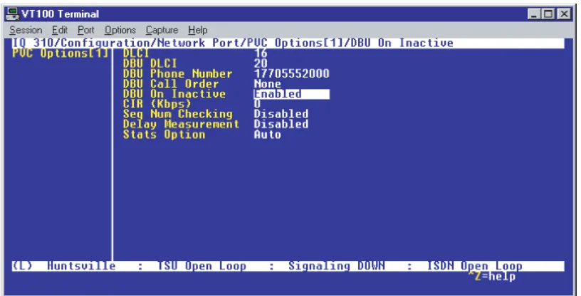
CFG-2 Example of the IQ 310 DBU on Inactive Group Parameter. . . 159
CFG-3 Frame Relay Primary Rate ISDN Dial Backup with the IQ 310 . . . 181
CFG-4 Example of the IQ 310 Call Order Parameter . . . 227
This section of ADTRAN’s IQ 310 System Manual is designed for use by network engineers, planners, and designers for overview information about the IQ 310.
It contains general information and describes physical and operational concepts, module functions, network relationships, provisioning, testing, alarm status, and system monitoring. This section should be used in conjunction with Section 2, Engineering Guidelines.
C
ONTENTSSystem Overview . . . 16
Features and Benefits . . . 16
Configuration and Management . . . 16
Software Upgradeable . . . 16
Statistics . . . 16
Network Module Descriptions . . . 17
56k/64k Network Interface Module (P/N 1202801L1) . . . 17
T1/FT1 Network Interface Module (P/N 1202802L1) . . . 17
T1/FT1 + DSX-1 Network Interface Module (P/N 1202803L1) . . . 17
T1 Probe Network Interface Module (P/N 1202804L1) . . . 17
Dial Backup Interface Modules . . . 18
V.34 DBU Module (P/N 1204002L3) . . . 18
ISDN BRI DBU Module (P/N 1204004L2). . . 18
ISDN PRI DBU Module (P/N 1204008L2). . . 18
1.
SYSTEM OVERVIEW
The IQ 310 is a performance monitoring device with monitoring capabilities up to Layer 3 of the network. This intelligent solution for managed Frame Relay access allows you to enjoy the monetary savings of Frame Relay and provides the visibility and control you need for physical connections made in Frame Relay networks.
The IQ 310 provides two slots (one for Dial Backup and one for a Network Interface Module) and features an Ethernet 10BaseT port for management applications. This product provides up to a full T1 worth of access or DDS.
The IQ 310 is complemented by ADTRAN’s network management software suite, called N-Form. N-Form is a modular, Java-enabled, Windows-based platform combining the features of a complete SNMP management platform with a network trend analysis tool. Using N-Form, the IQ 310 can be configured remotely through a graphical interface. All alarm conditions and monitoring matrices may be viewed in either graphical or tabular forms.
2.
FEATURES AND BENEFITS
The following is a brief list of IQ 310 features and benefits:
Configuration and Management
• ADTRAN N-Form web-based network management suite • Local and remote VT100 terminal via the CONTROL port
• SNMP
• Telnet in-band access through shared or dedicated PVC • 10BaseT interface for management access
• N-Formant (the N-Form Java Applet)
Software Upgradeable
• Flash memory• TFTP download
• XMODEM via CRAFT/CONTROL port
Statistics
• Access line statistics (T1 errors, alarms, tests, ...)
3.
NETWORK MODULE DESCRIPTIONS
The IQ 310 has four Network Interface Modules:• 56k/64k Network Interface Module (P/N 1202801L1) • T1/FT1 Network Interface Module (P/N 1202802L1)
• T1/FT1 + DSX-1 Network Interface Module (P/N 1202803L1) • T1 Probe Network Interface Module (P/N 1202804L1)
Each module has a variety of performance and alarm status information. Several features of each module are user-configurable, although default values reflect the most common configurations. All option modules contain an extensive self-test as well as tests designed for the technology they incorporate.
56k/64k Network Interface Module (P/N 1202801L1)
The 56k/64k Network Interface Module provides one 56k/64k interface for Frame Relay. This interface supports both 56k and 64k operation. The IQ 310 with 56k/64k Network Interface Module system (P/N 4203801L1) ships with one installed 56k/64k Network Interface Module.
T1/FT1 Network Interface Module (P/N 1202802L1)
The T1/FT1 Network Interface Module provides one channelized T1 interface for Frame Relay. This interface operates in DS-1 or DSX-1 mode and can deliver timing for the system. The IQ 310 with T1/FT1 Network Interface Module system (P/N 4203802L1) ships with one installed T1/FT1 Network Interface Module.
T1/FT1 + DSX-1 Network Interface Module (P/N 1202803L1)
The T1/FT1 + DSX-1 Network Interface Module provides one channelized T1 interface for Frame Relay and includes an additional DSX-1 interface for TDM voice applications. This T1 interface operates in DS-1 or DSX-1 mode and can deliver timing for the system. The IQ 310 with T1/FT1 + DSX-1 Interface Module system (P/N 4203803L1) ships with one installed T1/FT1 + DSX-1 Network Interface Module.
T1 Probe Network Interface Module (P/N 1202804L1)
4.
DIAL BACKUP INTERFACE MODULES
The IQ 310 has four Dial Backup Interface Modules:• V.34 DBU Module (P/N 1204002L3) • ISDN BRI DBU Module (P/N 1204004L2) • ISDN PRI DBU Module (P/N 1204008L2) • DCE DBU Module (P/N 1204006L2)
The IQ 310 Dial Backup (DBU) Modules provide single or multiple site backup, depending on the DBU Module option selected. The IQ 310 can be configured to originate a call based on physical layer
conditions (i.e., port failures) and/or PVC outages. Once the criteria are met, the IQ 310 establishes a call to the configured phone number and the connection is used to carry traffic for the PVC(s) configured for DBU operation.
V.34 DBU Module (P/N 1204002L3)
The V.34 DBU Module provides switched backup of the leased line application. This module allows backup data rates of up to 33.6 kbps over the public switched telephone network (PSTN).
ISDN BRI DBU Module (P/N 1204004L2)
The ISDN BRI DBU (basic rate interface dial backup) Module supports a U-interface to the Basic Rate ISDN and is compatible with National ISDN, Lucent 5ESS, DMS 100, and NEC. When a T1/FT1 or T1/FT1 + DSX-1 Network Interface Module is installed, the ISDN BRI DBU Module provides a 2B+D Basic Rate ISDN service. When a 56k/64k Network Interface Module is installed, the ISDN BRI DBU Module provides a 1B+D Basic Rate ISDN service.
ISDN PRI DBU Module (P/N 1204008L2)
The ISDN PRI DBU (primary rate interface dial backup) Module allows the IQ 310 to accept or place up to 23 dial backup calls simultaneously. This module supports 64 kbps data service. Incoming calls will be accepted for 56 kbps or 64 kbps service. Bonding is not supported. Fractional PRI capability is supported.
DCE DBU Module (P/N 1204006L2)
Provides information to assist network designers with incorporating the IQ 310 system into their networks.
C
ONTENTSEquipment Dimensions . . . 21
Power Requirements . . . 21
Reviewing the Front Panel Design . . . 21
LCD Window . . . 21
Enter Key . . . 21
Up and Down Arrow Keys . . . 21
Cancel Key . . . 22
Quick Key . . . 22
Numeric Keypad . . . 22
Next, Prev, Add, Delete Keys . . . 22
Shift Key . . . 22
Front Panel LEDs . . . 22
Reviewing the Rear Panel Design . . . 23
V.35 Nx56/64 Connector. . . 23
CRAFT/CONTROL Port (DB-9) . . . 24
LAN Ethernet Connection (RJ-48C) . . . 25
Network Interface Modules . . . 25
56k/64k Network Interface Module – RJ-48S (P/N 1202801L1) . . . 25
T1/FT1 Network Interface Module – RJ-48C (P/N 1202802L1) . . . 26
T1/FT1 + DSX-1 Network Interface Module – RJ-48C (P/N 1202803L1) . . . 27
T1 Probe Network Interface Module - RJ-48C (P/N 1202804L1) . . . 28
Dial Backup Interface Modules . . . 28
V.34 DBU Module (P/N 1204002L3) . . . 29
ISDN BRI DBU Module (P/N 1204004L2). . . 29
ISDN PRI DBU Module (P/N 1204008L2). . . 29
External DCE DBU Module (P/N 1204006L2). . . 30
F
IGURES Figure 1. IQ 310 Front Panel Layout . . . 21Figure 2. IQ 310 Rear Panel . . . 23
T
ABLES Table 1. IQ 310 LEDs . . . 22Table 2. V.35 Winchester Pinout . . . 24
Table 3. CRAFT/CONTROL Pinout . . . 25
Table 8. T1/FT1 + DSX-1 Network Interface Module Pinout (DSX Port) . . . 27
Table 9. T1 Network (RJ-48C) Connection Pinout . . . 28
Table 10. DTE Interface (RJ-48C) Pinout . . . 28
Table 11. V.34 DBU Module Pin Assignments . . . 29
Table 12. ISDN BRI DBU Module Pin Assignments . . . 29
Table 13. ISDN PRI DBU Module Pin Assignments . . . 29
1.
EQUIPMENT DIMENSIONS
The IQ 310 base unit is 8.1” W, 9.6” D, and 2.7” H. All other pieces of equipment (option modules) fit inside the base unit.
2.
POWER REQUIREMENTS
The IQ 310 has a maximum power consumption of 9.9 Watts and a maximum current draw of 82 milliAmps regardless of the configuration of option modules installed.
3.
REVIEWING THE FRONT PANEL DESIGN
The front panel contains the LCD display window, status LEDs, and keypad buttons. The LEDs provide visual information about the IQ 310 base unit and any option module that may be installed. Figure 1 identifies the LCD display window, the LEDs, and the keypad buttons.
Figure 1. IQ 310 Front Panel Layout
LCD Window
Displays menu items and messages in this 2 line by 16 character display.
Enter Key
Selects active menu items. To activate a menu item, scroll to it using the arrow keys or press the number of the item. The flashing cursor indicates the active parameter. Press <ENTER> to select the active menu item.
Up and Down Arrow Keys
Scrolls through the menu and activates the menu items of the current menu. The flashing cursor indicates LCD Window Up and Down arrows
Cancel Key
Press the CANCEL key to stop the current activity and return to the previous menu. Press repeatedly until the desired menu level is reached. When a submenu item is displayed, press CANCEL to exit the current display and return to the previous menu.
Quick Key
Pressing the QUICK key returns the front panel to the Main menu.
Numeric Keypad
The numeric keypad contains the numbers 0 through 9 and alpha characters A throughF, which are used to activate menu items and enter information such as the IP address.
Next, Prev, Add, Delete Keys
To activate these functions, press and release the SHIFT key, then press the NEXT, PREV, ADD, or
DELETE key. Use these keys when editing tables such as the PVC Options table.
Shift Key
Enter alpha characters by first pressing and releasing the SHIFT key and then pressing the desired character. The NEXT, PREV, ADD, and DELETE keys are also activated by first pressing SHIFT.
To activate a menu item designated by an alpha character rather than a number, place the cursor on the menu item using the up and down arrows or press and release SHIFT and then press the letter. The flashing cursor indicates the active parameter. Press <ENTER> to select the item.
Front Panel LEDs
With the IQ 310 powered-up, the front panel LEDs provide visual information about the status of the IQ 310 and any option modules that may be installed. Table 1 provides detailed information about the front panel LEDs.
Table 1. IQ 310 LEDs
For these LEDs... This color light... Indicates that...
RS (Request to Send) Green there is an active RS signal on DTE interface. CS (Clear to Send) Green there is an active CS signal on DTE interface. TD (Transmit Data) Green (flashes) there is transmit data activity on the DTE interface. RD (Receive Data) Green (flashes) there is receive data activity on the DTE interface. ERR (Error) Red (flashes) there is an active T1 line code violation or T1 path code
4.
REVIEWING THE REAR PANEL DESIGN
The IQ 310 rear panel contains two expansion slots (one for Dial Backup and one for a Network Interface Module), a DTE connector which provides primary channel V.35, and an Ethernet 10BaseT port for management applications (see Figure 2).
Figure 2. IQ 310 Rear Panel
V.35 Nx56/64 Connector
The DTE should be connected to the V.35 connector (labeled V.35) with a maximum cable length of 100 feet. Table 2 on page 24 shows the pinout for the V.35 Winchester-style connector.
ALM (Alarm) Red one of the following alarm conditions exists:
• Loss of signal
• Loss of T1 frame sync (red alarm)
• Receiving AIS (alarm indication signal) from the service provider
• Frame Relay signaling is down.
TST (Test) Amber the network interface is in a loopback condition triggered
locally or from the service provider.
DBU (Dial Backup) Red the unit is in dial backup.
Table 1. IQ 310 LEDs (Continued)
CRAFT/CONTROL Port (DB-9)
The CRAFT/CONTROL port (EIA-232) connects to a computer or modem or to a VT100 terminal. The
CRAFT/CONTROL port input provides the following functions:
• Accepts EIA-232 input from a PC or a modem for controlling the IQ 310 • Operates at 9600, 19200, 38400, or 57600 bps
• Acts as input for either VT100 terminal or PC control
• Acts as an interface for flash memory software downloads using XMODEM
Table 3 on page 25 shows CRAFT/CONTROL pinout.
Table 2. V.35 Winchester Pinout
Pin CCITT DESCRIPTION
A 101 Protective ground (PG)
B 102 Signal ground (SG)
C 105 Request to send (RTS) from DTE
D 106 Clear to send (CTS) to DTE
E 107 Data set ready (DSR) to DTE
F 109 Received line signal detector (DCD) to DTE
H — Data terminal ready (DTR) from DTE
J — Ring indicator (RI)
R 104 Received data (RD-A) to DTE
T 104 Received data (RD-B) to DTE
V 115 RX clock (RC-A) to DTE
X 115 RX clock (RC-B) to DTE
P 103 Transmitted data (TD-A) from DTE
S 103 Transmitted data (TD-B) from DTE
Y 114 TX clock (TC-A) to DTE
AA 114 TX clock (TC-B) to DTE
U 113 External TX clock (ETC-A) from DTE
W 113 External TX clock (ETC-B) from DTE
.
LAN Ethernet Connection (RJ-48C)
The LAN port provides a 10BaseT Ethernet connection, which is used for IP Routing,TFTP, SNMP, and Telnet connection. Table 4 shows the pinout.
5.
NETWORK INTERFACE MODULES
The IQ 310 provides two expansion slots that allow different types of interfaces to be used. The following is a discussion of the available Network Interface Modules.
56k/64k Network Interface Module – RJ-48S (P/N 1202801L1)
The 56k/64k Network Interface Module provides a single 8-position modular jack to connect to the DDS network. The 56k/64k Network Interface Module provides the following functions:
• Network performance monitoring and reporting • Extensive self-testing
Table 5 on page 26 shows the 56k/64k NIM pinout.
Table 3. CRAFT/CONTROL Pinout
PIN NAME DESCRIPTION
1 DCD Carrier detect
2 RD Data received by the IQ 310
3 TD Data transmitted by the IQ 310
4 DTR Data terminal ready
5 GND Ground - connected to unit chassis
6 DSR Data set ready
7 RTS Request to send - flow control
8 CTS Clear to send - flow control
9 UNUSED —
Table 4. LAN Ethernet Pinout
PIN NAME DESCRIPTION
1 TX1 Transmit positive
2 TX2 Transmit negative
3 RX1 Receive positive
4, 5 UNUSED —
6 RX2 Receive negative
T1/FT1 Network Interface Module – RJ-48C (P/N 1202802L1)
The T1/FT1 Network Interface Module provides a single T1 port and complies with the applicable ANSI and AT&T® standards. The T1/FT1 Network Interface Module provides the following functions:
• AMI or B8ZS coding • Manual line build-out • D4 or ESF framing
• Network performance monitoring and reporting • Test loopbacks
• Extensive self-testing
Table 6 shows the T1/FT1 NIM pinout.
Table 5. 56k/64k Network Interface Module Pinout
PIN NAME DESCRIPTION
1 R1 Transmit data toward the network - Ring 1
2 T1 Transmit data toward the network - Tip 1
3 UNUSED —
4 UNUSED —
5 UNUSED —
6 UNUSED —
7 T Receive data from the network - Tip
8 R Receive data from the network - Ring
Table 6. T1/FT1 Network Interface Module Pinout
PIN NAME DESCRIPTION
1 R1 RXDATA-RING Receive data from the network 2 T1 RXDATA-TIP Receive data from the network
3 — UNUSED —
4 R TXDATA-RING Transmit data toward the network 5 T TXDATA-TIP Transmit data toward the network
T1/FT1 + DSX-1 Network Interface Module – RJ-48C (P/N 1202803L1)
The T1/FT1 + DSX-1 Network Interface Module provides one T1 port and one DSX-1 port and complies with the applicable ANSI and AT&T® standards. The T1/FT1 + DSX-1 Network Interface Module provides the following functions:
• AMI or B8ZS coding • Manual line build-out • D4 or ESF framing
• Network performance monitoring and reporting • Test loopbacks
• Extensive self-testing
The pinouts for the T1/FT1 + DSX-1 NIM T1 and DSX-1 ports are shown in Table 7 and Table 8 below.
Table 7. T1/FT1 + DSX-1 Network Interface Module Pinout (T1 Port)
PIN NAME DESCRIPTION
1 R1 RXDATA-RING Receive data from the network 2 T1 RXDATA-TIP Receive data from the network
3 — UNUSED —
4 R TXDATA-RING Transmit data toward the network 5 T TXDATA-TIP Transmit data toward the network
6, 7, 8 — UNUSED —
Table 8. T1/FT1 + DSX-1 Network Interface Module Pinout (DSX Port)
PIN NAME DESCRIPTION
1 R1 TXDATA-RING Transmit data toward the PBX 2 T1 TXDATA-TIP Transmit data toward the PBX
3 — UNUSED —
4 R RXDATA-RING Receive data from the PBX
5 T RXDATA-TIP Receive data from the PBX
T1 Probe Network Interface Module - RJ-48C (P/N 1202804L1)
The T1 Probe Network Interface Module provides a T1 NETWORK interface and a T1 DTE interface. The T1 Probe complies with the applicable ANSI and AT&T® standards and provides the following functions:
• AMI or B8ZS coding • Manual line build-out • D4 or ESF framing
• Network performance monitoring and reporting • Test loopbacks
• Extensive self-testing
Table 9 and Table 10 show the T1 Probe NIM pinout.
6.
DIAL BACKUP INTERFACE MODULES
The IQ 310 provides two expansion slots that allow different types of interfaces to be used. The following is a discussion of the available Dial Backup Interface Modules.
Table 9. T1 Network (RJ-48C) Connection Pinout
Pin Name Description
1 R1 Receive data from the network 2 T1 Receive data from the network
3 — UNUSED
4 R Transmit data toward the network 5 T Transmit data toward the network
6-8 — UNUSED
Table 10. DTE Interface (RJ-48C) Pinout
Pin Name Description
1 R1 Transmit data toward the DTE device 2 T1 Transmit data toward the DTE device
3 — UNUSED
V.34 DBU Module (P/N 1204002L3)
The following table shows the pinouts for the V.34 DBU Module.
ISDN BRI DBU Module (P/N 1204004L2)
The following table shows the pinouts for the ISDN BRI DBU Module.
ISDN PRI DBU Module (P/N 1204008L2)
The following table shows the pinouts for the ISDN PRI DBU Module.
Table 11. V.34 DBU Module Pin Assignments
Pin Name Description
1-3 - Not used
4 T Network-Tip
5 R Network-Ring
6-8 - Not used
Table 12. ISDN BRI DBU Module Pin Assignments
Pin Name Description
1-3 - Not used
4 T Network-Tip
5 R Network-Ring
6-8 - Not used
Table 13. ISDN PRI DBU Module Pin Assignments
Pin Name Description
1 R1 RXDATA-RING Receive data from the network
2 T1 RXDATA-TIP Receive data from the network
3 UNUSED
--4 R TXDATA-RING Send data toward network
5 T TXDATA-TIP Send data toward network
--External DCE DBU Module (P/N 1204006L2)
The following table shows the pinouts for the DCE DBU Module.
Table 14. DCE Connector Pin Assignments
DB25 Pin# V.35 Pin# Function DTE Port Direction DCE Port Direction
1 A FGND
2 TD(EIA-232) I O
3 RD(EIA-232) O I
4 C RTS I O
5 D CTS O I
6 E DSR O I
7 B GND
8 F DCD O I
9 NEG
10 POS
11 AA TC-B(V.35) O I
12 Y TC-A(V.35) O I
13 V RC-A(V.35) O I
14 T RC-B(V.35) O I
15 TC(EIA-232) O I
16 R RD-A(V.35) O I
17 RC
18 S TD-B(V.35) I O
19 P TD-A(V.35) I O
20 H DTR I O
21 W ETC-B(V.35) I O
22 - - -
-23 U ETC-A(V.35) I O
24 ETC(EIA-232) I O
25 X RC-B(V.35) O I
Provides shipment contents list, grounding instructions, mounting options, and specifics of supplying power to the unit.
C
ONTENTSIntroduction . . . 32 Unpack and Inspect the SYSTEM . . . . 32 Contents of ADTRAN Shipments . . . 32 Grounding Instructions . . . 33 Supplying Power to the Unit . . . 33
1.
INTRODUCTION
This section discusses installation of the IQ 310 system.
2.
UNPACK AND INSPECT THE SYSTEM
Each IQ 310 is shipped in its own cardboard shipping carton. Open each carton carefully and avoid deep penetration into the carton with sharp objects.
After unpacking the unit, inspect it for possible shipping damage. If the equipment has been damaged in transit, immediately file a claim with the carrier, then contact ADTRAN Customer Service (see Warranty and Customer Service Information in the front of this manual).
Contents of ADTRAN Shipments
Your ADTRAN shipment includes the following items:
• The IQ 310 base unit
• The IQ 310System CD including the System Manual and ADTRAN Utilities • RJ-45 to RJ-45 cable - ADTRAN P/N 3127004
• AC power cord - ADTRAN P/N 3127031
• Network Interface Module and appropriate contents (depending on system level part number) – 4203801L1 IQ 310 with 56k/64k Network Interface Module
– 4203802L1 IQ 310 with T1 Network Interface Module
– 4203803L1 IQ 310 with T1 with DSX Network Interface Module – 4203804L1 IQ 310 with T1 Probe Network Interface Module
To prevent electrical shock, do not install equipment in a wet location or during a lightning storm.
Electronic modules can be damaged by static electrical discharge. Before handling modules, wear an antistatic discharge wrist strap to prevent damage to electronic components. Place modules in antistatic packing material when transporting or storing. When working on modules, always place them on an approved antistatic mat that is electrically grounded.
3.
GROUNDING INSTRUCTIONS
The following provides grounding instruction information from the Underwriters’ Laboratory UL 60950 Standard for Safety of Information Technology Equipment Including Electrical Business Equipment, of December, 2000.
An equipment grounding conductor that is not smaller in size than the ungrounded branch-circuit supply conductors is to be installed as part of the circuit that supplies the product or system. Bare, covered, or insulated grounding conductors are acceptable. Individually covered or insulated equipment grounding conductors shall have a continuous outer finish that is either green, or green with one or more yellow stripes. The equipment grounding conductor is to be connected to ground at the service equipment.
The attachment-plug receptacles in the vicinity of the product or system are all to be of a grounding type, and the equipment grounding conductors serving these receptacles are to be connected to earth ground at the service equipment. A supplementary equipment grounding conductor shall be installed between the product or system and ground that is in addition to the equipment grounding conductor in the power supply cord.
The supplementary equipment grounding conductor shall not be smaller in size than the ungrounded branch-circuit supply conductors. The supplementary equipment grounding conductor shall be connected to the product at the terminal provided, and shall be connected to ground in a manner that will retain the ground connection when the product is unplugged from the receptacle. The connection to ground of the supplementary equipment grounding conductor shall be in compliance with the rules for terminating bonding jumpers at Part K or Article 250 of the National Electrical Code, ANSI/NFPA 70. Termination of the supplementary equipment grounding conductor is permitted to be made to building steel, to a metal electrical raceway system, or to any grounded item that is permanently and reliably connected to the electrical service equipment ground.
The supplemental grounding conductor shall be connected to the equipment using a number 8 ring terminal and should be fastened to the grounding lug provided on the rear panel of the equipment. The ring terminal should be installed using the appropriate crimping tool (AMP P/N 59250 T-EAD Crimping Tool or equivalent).
4.
SUPPLYING POWER TO THE UNIT
The AC-powered IQ 310 comes equipped with a detachable 8-foot power cord with a 3-prong plug for connecting to a grounded power receptacle. As shipped, the IQ 310 is set to factory default conditions. After installing the base unit and any option modules, the IQ 310 is ready for power-up. To power-up the
• This unit shall be installed in accordance with Article 400 and 364.8 of the NEC NFPA 70 when installed outside of a Restricted Access Location (i.e., central office, behind a locked door, service personnel only area).
• Power to the IQ 310 must be from a grounded 115 VAC, 60 Hz source. • The power receptacle uses double-pole, neutral fusing.
5.
MOUNTING OPTIONS
The IQ 310 base unit may be installed for tabletop, 19-inch or 23-inch rack mount, or wall mount configuration. Shelves may be purchased from ADTRAN to achieve the rack mount configuration.
6.
INSTALLING NETWORK AND DIAL BACKUP INTERFACE MODULES
Figure 1 shows the option slot numbering designation as viewed from the rear of the IQ 310. The network slot accepts only IQ 310 Network Interface Modules, and the DBU slot accepts any of the IQ Series Dial Backup Interface Modules.
Figure 1. IQ 310 Slot Designation (Rear Panel)
Be careful not to upset the stability of the equipment mounting rack when installing this product.
Option modules are intended to be serviced by qualified service personnel only.
Modules are not hot swappable.
Instructions for Installing the IQ 310 Network and Dial Backup Interface Modules
56k/64k Network Interface Module (P/N 1202801L1)
Shipping Contents
The ADTRAN shipment of the 56k/64k Network Interface Module includes the following items:
• 56k/64k Network Interface Module
• 56k/64k Network Interface Module Quick Start Guide • RJ-45 to RJ-45 cable - ADTRAN P/N 3127004
T1/FT1 Network Interface Module (P/N 1202802L1)
Shipping Contents
The ADTRAN shipment of the T1/FT1 Network Interface Module includes the following items:
• T1/FT1 Network Interface Module
• T1/FT1 Network Interface Module Quick Start Guide • RJ-45 to RJ-45 cable - ADTRAN P/N 3127004
T1/FT1 + DSX-1 Network Interface Module (P/N 1202803L1)
Shipping Contents
The ADTRAN shipment of the T1/FT1 + DSX-1 Network Interface Module includes the following items:
Instructions for Installing the IQ 310 Option Modules
Step Action
1. Power off the unit.
2. Remove the cover plate from the appropriate option slot of the IQ 310 rear panel.
3. Slide the option module into the option slot until the module is firmly seated against the front of the chassis.
4. Secure the tabs at both edges of the module. 5. Connect the cables to the associated device(s).
6. Complete installation of remaining modules and base unit as specified in the appropriate sections of this Network Turnup Procedure.
T1 Probe Network Interface Module (P/N 1202804L1)
Shipping Contents
The ADTRAN shipment of the T1 Probe Network Interface Module includes the following items:
• T1 Probe Network Interface Module
This section of ADTRAN’s IQ 310 System Manual is designed for use by network administrators and others who will configure and provision the system. It contains information about navigating the VT100 user interface and using the front panel LCD display.
C
ONTENTSNavigating the Terminal Menu . . . 38 Terminal Menu Window . . . 38 Navigating Using the Keyboard Keys . . . 40 Terminal Menu and System Control . . . 41 Selecting the Appropriate Menu . . . 41 Menu Descriptions . . . 42 Configuration Menus . . . 42 Stats Menu . . . 60 Menu Viewing Options . . . 60 Test Menu . . . 78 Dial Menu . . . 81 Utilities Menu. . . 82
F
IGURESFigure 1. Top-Level Terminal Menu Window . . . 38 Figure 2. Alternate Menu View . . . 39 Figure 3. Example of Interval View . . . 61 Figure 4. Test Menu . . . 78
T
ABLES1.
NAVIGATING THE TERMINAL MENU
Terminal Menu Window
The IQ 310 uses a multi-level menu structure that contains both menu items and data fields. All menu items and data fields display in the terminal menu window (see Figure 1), through which you have complete control of the IQ 310.
Figure 1. Top-Level Terminal Menu Window
Menu Path
The first line of the terminal menu window (the menu path) shows the session’s current position (path) in the menu structure. For example, Figure 1 shows the top-level menu with the cursor on the CONFIGURATION submenu; therefore, the menu path reads IQ 310/CONFIGURATION.
Window Panes
When you first start a terminal menu session, the terminal menu window is divided into left and right panes. The left pane shows the list of available submenus, while the right pane shows the contents of the currently selected submenu.
You can view the terminal windows in two ways: with fields and submenus displaying horizontally across the right pane, or with fields and submenus displaying vertically down the right pane. Viewing submenus vertically rather than horizontally allows you to see information at a glance rather than scrolling
horizontally across the window. To change the view, move your cursor to an index number and press
<ENTER>. Figure 2 shows this alternate view. Fields and submenu names may vary slightly in this view. System Name
Network Status
Right Pane
Signaling Status Navigation Help
Menu Path
Left Pane
Figure 2. Alternate Menu View
Window Pane Navigation
Use the following chart to assist you in moving between and within the two window panes.
Right Window Pane Notation
The right window pane shows the contents of the currently selected menu. These contents can include both submenu items and data fields. Some submenus contain additional submenus and some data fields contain additional data fields. The chart on the following page explains the notation used to identify these additional items.
To do this... Press one of the following keys...
Move from left pane to right pane
Tab Enter Right arrow
Move from right pane to left pane
Shift+Tab Escape Left arrow Backspace
Move within each pane
Additional Terminal Menu Window Features
• Login Type - Displays L when menu reflects the local unit, R for a remote unit, and T during a Telnet session.
• System Name - Displays the name entered in the SYSTEM NAMEfield. • Network Status - Displays the current state of the incoming network circuit. • Signaling Status - Displays the current LMI state of the network interface.
• DBU Status - Displays the current state of the DBU service (available when a DBE module is installed). • Navigation Help - Lists characters used for navigating the terminal menu <CTRL + Z>.
Navigating Using the Keyboard Keys
You can use various keystrokes to move through the terminal menu, to manage a terminal menu session, and to configure the system. Press <CTRL + Z> to activate a pop-up screen listing the navigation
keystrokes.
Moving through the Menus
This notation... Means that...
[+] More items are available when selected.
<+> An action is to be taken, such as activating a test. Highlighted field You can enter data in this field.
Underlined field The field contains read-only information.
To do this... Press this key...
Return to the home screen H
Select items Arrows
Edit a selected menu item Enter
Cancel an edit Escape
Close pop-up help screen Escape
Move between the left and right panes ArrowsTab
Move to the top of a screen A
Move to the bottom of a screen Z
Session Management Keystrokes
Configuration Keystrokes
Getting Help
Press <CTRL + Z> to activate a help screen that displays the available keystrokes you can use to navigate the terminal menu.
2.
TERMINAL MENU AND SYSTEM CONTROL
Selecting the Appropriate Menu
The terminal menu is the access point to all other operations. Each terminal menu item has several functions and submenus that identify and provide access to specific operations and parameters. Use the chart below to help select the appropriate terminal menu.
To do this... Press this key...
Log out of a session CTRL + L
Refresh the screen
To save time, only the portion of the screen that has changed is refreshed. This option should only be necessary if the display picks up incorrect characters.
CTRL + R
To do this... Press this key...
Insert a new list item.
For example, add a new item to the list by pressing <I> while the cursor is over the index number.
I
Delete a list item.
For example, delete an item from the list by pressing <D> while the cursor is over the index number.
D
To do this... Go to this menu...
Set network operating parameters for the DTE, network, and dial backup interfaces, to provision system options.
CONFIGURATION
Display status information for the DTE port, network port, DBU port, ETHERNET port, CRAFT/CONTROL port, and system.
VIEW STATISTICS
Activate ping, Net and DTE loopback, and PVC loopback testing functions.
TEST
Access dialing functions (only available when DBU module is installed). DIAL
3.
MENU DESCRIPTIONS
C
ONFIGURATIONM
ENUSC
ONFIGURATION> DTE P
ORT> P
HYSICALL
AYERO
PTIONS> F
LOWC
ONTROLThis option determines how the IQ 310 responds to congestion during DBU operation.
C
ONFIGURATION> DTE P
ORT> P
HYSICALL
AYERO
PTIONS> CTS O
PTIONSet the CTS lead to FORCED ON or FOLLOW RTS.
C
ONFIGURATION> DTE P
ORT> P
HYSICALL
AYERO
PTIONS> DSR O
PTIONSet the DSR lead to FORCED ON or NORMAL.
C
ONFIGURATION> DTE P
ORT> P
HYSICALL
AYERO
PTIONS> CD O
PTIONSet the CD lead to FORCED ON or NORMAL.
The following PHYSICAL LAYER OPTIONSdo not apply if the T1 Probe Network Interface
Module is installed.
NONE - No flow control is used and the IQ 310 drops frames during severe congestion while in DBU operation.
HARDWARE - The IQ 310 varies the DTE TC clock as necessary to relieve congestion during DBU operation.
FECN/BECN - While in a congested state during DBU operation, frames across the DBU PVCs have
FECN or BECN set depending on the direction. Frames outbound to the network have FECN set, while frames inbound to the attached DTE device have BECN set. This method is useful if the attached DTE devices can respond to congestion notification.
FORCED ON - The CTS lead is always on and the RTS lead is ignored.
FOLLOW RTS - The CTS lead is on when the RTS lead is on (and off when the RTS lead is off).
FORCED ON - The DSR lead is always on.
NORMAL - The DSR lead is off when the IQ 310 is in a loopback test or an alarm state.
FORCED ON - The CD lead is always on.
C
ONFIGURATION> DTE P
ORT> P
HYSICALL
AYERO
PTIONS> TC C
LOCKO
PTIONC
ONFIGURATION> DTE P
ORT> F
RAMER
ELAYO
PTIONSUse the following selections to configure timeout intervals and error thresholds, and to configure PVC management settings.
C
ONFIGURATION> DTE P
ORT> F
RAMER
ELAYO
PTIONS> T392
Set the timeout (in seconds) between polling intervals. This parameter needs to be a few seconds longer than the T391 setting of the attached frame relay device. Range is 5 to 30 seconds.
C
ONFIGURATION> DTE P
ORT> F
RAMER
ELAYO
PTIONS> N392
ANDN393
These parameters define the error threshold for the UNI (user to network interface) formed by the IQ 310 DTE port and the attached frame relay device. If the error threshold is met, the signaling state status is changed to down, which indicates a service-affecting condition. This condition is cleared once N393 consecutive error-free events are received. N392 defines the number of errors required in a given event window, while N393 defines the number of polling events in each window.
For example:
If N392=3 and N393=4, then if three errors occur within any four events, the interface is determined inactive.
The status of the connection can be viewed in the VIEW STATISTICS > DTE PORT > SIGNAL STATE menu (see Stats Menu on page 60). The status returns to ACTIVE once the threshold is no longer exceeded.
NORMAL - Clock for DTE's transmit data normal phase.
INVERTED - Clock for DTE's transmit data inverted phase. May be used in high speed circuits (>512 kbps) when the DTE's V.35 interface has high delay. This is usually indicated by HDLC errors on the IQ 310's DTE port.
C
ONFIGURATION> DTE P
ORT> F
RAMER
ELAYO
PTIONS> M
ANAGEMENTDLCI
To use local PVC management, enter the management data link connection identifier (DLCI). The
MANAGEMENT DLCI is a special DLCI used between the attached DTE device and the IQ 310 to carry SNMP and Telnet packets to/from the IQ 310 on the DTE port.
Guidelines for Configuring Management DLCI
If the attached router or FRAD is used to route SNMP/Telnet frames to the IQ 310, set the
MANAGEMENT DLCI to a unique value (between 16 and 1007) that identifies the virtual circuit between the router/FRAD and the IQ 310. The router/FRAD must also be configured to route the IQ 310 IP address to this DLCI. The IP ADDRESS and SUBNET MASK for the DTE (V.35) port must also be set in the SYSTEM CONFIGURATION menu.
C
ONFIGURATION> DTE P
ORT> F
RAMER
ELAYO
PTIONS> M
ANAGEMENTPVC O
PTIONIf this option is set to ENABLED, the management DLCI is included in the Full Status response to the router. Enable this option when the management DLCI is used to route management traffic to the IQ 310. Options are ENABLED and DISABLED.
C
ONFIGURATION> DTE P
ORT> F
RAMER
ELAYO
PTIONS> S
IGNALINGR
ESPONSESThis option determines when PVC SIGNALING RESPONSESare sent to the router.
C
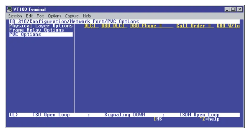
ONFIGURATION> N
ETWORKP
ORT> P
HYSICALL
AYERO
PTIONS> T1 + DSX NIM
ALWAYS ON - If enabled, PVC SIGNALING RESPONSES are sent to the router regardless of the network signaling state. Enable this option when the IQ 310 is used for dial backup.
FOLLOW NETWORK (FOLLOW NET) - If enabled, PVC SIGNALING RESPONSES are sent to the router only when the network signaling state is up. Enable this option when the router is going to use an alternate path for dial backup.
ALWAYS OFF - If enabled, PVC signaling responses are NOT sent to the router, regardless of the network signaling state. Enable this option to simulate a PVC failure when the router is going to use an alternate path for dial backup.
The following NETWORK > PHYSICAL LAYER OPTIONS are in groups based on the Network
Interface Module (NIM).
CHANNEL MAP - This field allows the user to map each individual DS0 to the DSX-1 port or to the DTE port, or to set it to IDLE.
DS01 . . . DS024 - Listing of individual DS0s in the Channel Map.
C
ONFIGURATION> N
ETWORKP
ORT> P
HYSICALL
AYERO
PTIONS> T1 NIM
D4 is equivalent to superframe format (SF).
LINE CODE - Set the line code for the network interface. Choices: AMI (alternate mark inversion) or B8ZS.
CLOCK SOURCE - Select the clock source to be derived from the network or from the unit’s internal clock. The selected clocking option designates the clock source for transmission. Clocking necessary for receiving data is recovered from incoming data. This option is most commonly set to FROM NETWORK.
Choices: INTERNALand FROM NETWORK.
LINE BUILDOUT (LBO) - Select the line buildout for the network interface. In AUTO mode, the IQ 310 sets the LBO based on the strength of the receive signal. Options: AUTO, 0, 7.5, 15, and 22.5 DB.
RX GAIN - Select the desired receiver sensitivity setting. The factory default is NORMAL, which is adequate for most applications. The extended setting should be used only in applications where the
NORMALsetting is not sufficient. If the receive signal strength is less than 30 dB, choose EXTENDED. CHANNEL RATE - Set the channel bandwidth for 56 or 64kbps.
TRANSMIT PRM - Enabling performance report messages (PRM) allows the IQ 310 to send messages across the facility data link (FDL) per ANSI T1.403. The terminating device at the telco may use this information for management of the T1 loop.The IQ 310 supports PRM messages per AT&T Pub 54016 which is a poll/response type protocol. Because of this poll/response nature, the transmit PRM option does not disable the IQ 310 from processing or responding to 54016-type messages.
Choices: YES or NO.
FRAMING FORMAT- Set the frame format for the network interface. Choices: D4, ESF, and AUTO.
D4 is equivalent to superframe format (SF).
LINE CODE - Set the line code for the network interface. Choices: AMI (alternate mark inversion) or B8ZS.
CLOCK SOURCE - Select the clock source to be derived from the network or from the unit’s internal clock. The selected clocking option designates the clock source for transmission. Clocking necessary for receiving data is recovered from incoming data. This option is most commonly set to FROM NETWORK.
C
ONFIGURATION> N
ETWORKP
ORT> P
HYSICALL
AYERO
PTIONS> 56/64K NIM
C
ONFIGURATION> N
ETWORKP
ORT> P
HYSICALL
AYERO
PTIONS> T1 P
ROBENIM
RX GAIN- Select the desired receiver sensitivity setting. The factory default is NORMAL, which is adequate for most applications. The extended setting should be used only in applications where theNORMALsetting is not sufficient. If the receive signal strength is less than 30 dB, choose EXTENDED. CHANNEL RATE - Set the channel bandwidth for 56 or 64KBPS.
CHANNEL ALIGNMENT - This field allows the user to select the channel alignment to be CONTIGUOUS or ALTERNATING.
START CHANNEL - Select the channel in which the T1 stream starts. The setting must be consistent with the carrier if using a public network. The range is 1 to 24.
NUMBEROF CHANNELS - Select the number of DS0s (channels) to be used. The range is 1 to 24. TRANSMIT PRM - Enabling performance report messages (PRM) allows the IQ 310 to send messages across the facility data link (FDL) per ANSI T1.403. The terminating device at the telco may use this information for management of the T1 loop.The IQ 310 supports PRM messages per AT&T Pub 54016 which is a poll/response type protocol. Because of this poll/response nature, the transmit PRM option does not disable the IQ 310 from processing or responding to 54016-type messages.
Choices: YES or NO.
LOOP RATE - Set the loop rate for 56 KBPS, 64 KBPS, or AUTO.
CLOCK SOURCE - Configure the IQ 310 to derive clocking from itself (INTERNAL) or from the network. The most common application is FROM NETWORK.
FRAMING FORMAT - Set the frame format for the network interface. Choices: D4, ESF, and AUTO.
LINE CODE - Set the line code for the network interface. Choices: AMI (alternate mark inversion) or B8ZS.
CLOCK SOURCE - Select the clock source to be derived from the network or from the unit’s internal clock. The selected clocking option designates the clock source for transmission. Clocking necessary for receiving data is recovered from incoming data. This option is most commonly set to FROM NETWORK.
Choices: INTERNAL and FROM NETWORK.
LINE BUILDOUT (LBO) - Select the line buildout for the network interface. In AUTO mode, the IQ 310 sets the LBO based on the strength of the receive signal.
Options: AUTO, 0, 7.5, 15, and 22.5 DB.
RX SENSITIVITY - Select the desired receiver sensitivity setting. The factory default is NORMAL, which is adequate for most applications. The extended setting should be used only in applications where the
C
ONFIGURATION> N
ETWORKP
ORT> F
RAMER
ELAYO
PTIONS> S
IGNALT
YPESet the signaling type option to match the network signaling type. AUTO mode forces the IQ 310 to use the same signaling type as the attached frame relay DTE. If AUTO is selected and there is no DTE device attached, the IQ 310 uses ANSI T1.617-D signaling type.
Choices: NONE, LMI (gang of four), ANSI T1.617-D (Annex D), ITU-T Q.933-A (Annex A), or AUTO.
C
ONFIGURATION> N
ETWORKP
ORT> F
RAMER
ELAYO
PTIONS> S
IGNALP
OLLSSet the signal polls to either NORMAL or FOLLOWS DTE. If set to NORMAL, the signal state will reflect the signal state of the network. If set to FOLLOWS DTE, the signal state will reflect the signal state of the DTE device.
C
ONFIGURATION> N
ETWORKP
ORT> F
RAMER
ELAYO
PTIONS> T391
Set the time (in seconds) between polls to the frame relay network.
C
ONFIGURATION> N
ETWORKP
ORT> F
RAMER
ELAYO
PTIONS> N391
Determine how many link integrity polls occur in between full status polls.
CHANNEL ALIGNMENT - This field allows the user to select the channel alignment to be CONTIGUOUS or ALTERNATING.
START CHANNEL -Select the channel in which the T1 stream starts. The setting must be consistent with the carrier if using a public network. The range is 1 to 24.
TRANSMIT PRM - Enabling performance report messages (PRM) allows the IQ 310 to send messages across the facility data link (FDL) per ANSI T1.403. The terminating device at the telco may use this information for management of the T1 loop.The IQ 310 supports PRM messages per AT&T Pub 54016 which is a poll/response type protocol. Because of this poll/response nature, the transmit PRM option does not disable the IQ 310 from processing or responding to 54016-type messages.
Choices: YES or NO.
The following NETWORK PORT and FRAME RELAY OPTIONS applies to all Network
C
ONFIGURATION> N
ETWORKP
ORT> F
RAMER
ELAYO
PTIONS> N392
ANDN393
These parameters define the error threshold for the UNI formed by the IQ 310 network port and the frame relay switch. If the error threshold is met, the signaling state is changed to down, which indicates a service-affecting condition. This condition is cleared once N393 consecutive error-free events are received. N392 defines the number of errors required in a given event window, while N393 defines the number of polling events in each window.
For example:
If N392=3 and N393= 4, then if three errors occur within any four events the interface is determined inactive.
The status of the connection can be viewed in the STATISTICS menu under NETWORK PORT SIGNALING STATE. The status will return to active again once the threshold is no longer exceeded.
C
ONFIGURATION> N
ETWORKP
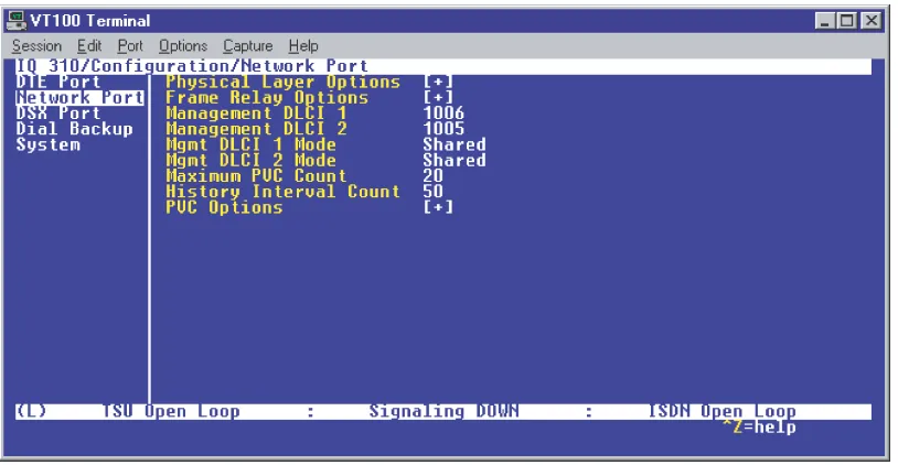
ORT> M
ANAGEMENTDLCI 1
ANDDLCI 2
Enter the management data link connection identifiers (DLCIs). These DLCIs are used to carry management traffic to and from the network.
C
ONFIGURATION> N
ETWORKP
ORT> M
GMTDLCI 1
ANDDLCI 2 M
ODESet to DEDICATED if the management DLCI is used only to manage the IQ 310 (and not used to carry customer traffic). If set to DEDICATED, the router is not notified of that DLCI. Set to SHARED if the management DLCI is used for carrying customer traffic and management data.
C
ONFIGURATION> N
ETWORKP
ORT> M
AXIMUMPVC C
OUNTSet the maximum number of PVCs that the IQ 310 will monitor for statistical information. This value determines the amount of history intervals available for storage. To get the maximum amount of statistical history storage, set this value equal to the number of PVCs assigned to the frame relay port. A smaller value increases history interval count.
C
ONFIGURATION> N
ETWORKP
ORT> H
ISTORYI
NTERVALC
OUNTSet the number of history intervals to store for statistics. History intervals are d