Analytical and experimental seismic qualification of three types of electric
transformers
Dimitar Stefanov1
1
Associate Professor, Bulgarian Academy of Sciences, Central Laboratory for Seismic Mechanics and Earthquake Engineering, Sofia, Bulgaria
ABSTRACT
The aim of the paper is to demonstrate the procedure and results of the seismic qualification of three types of electric transformers - current, voltage and combined. Such complex investigation of this kind of transformers is done for the first time in Bulgaria. The transformers are qualified for a maximum seismic excitation in the Republic of Bulgaria – IX degree of seismic intensity. The seismic qualification is performed by 2 methods: analytical qualification and experimental qualification – by seismic test on the special vibration platform (shaking table).
INTRODUCTION
The transformers are produced from Hyundai Heavy Industries Co., Bulgaria. There are three parts, which build each transformer: a lower zone with a core, a bushing from special glanced porcelain and an upper zone with steel cover. The transformers can be located at the site anywhere in Bulgaria.
Three types of supporting structures for the first two transformers (current and voltage) are possible: - Type 1 - reinforced concrete foundation on the ground surface level for one transformer;
- Type 2 - steel support structure for 3 transformers; - Type 3 - reinforced concrete column for one transformer.
The combined transformer always is mounted on the reinforced concrete foundation on the ground surface level. The weights are as follows: current t-r G=645 kg, voltage t-r G=465 kg, combined t-r G=885 kg.
DEFINITION OF THE SEISMIC EXCITATION
The three types of transformers are qualified for a maximum seismic excitation in the Republic of Bulgaria – IX degree of seismic intensity. Up to now this is described in "Code for Design of Buildings and Structures in Seismic Regions" (CDBSSR) – 1987 year. The relevant document for European Union is: "Eurocode 8: Design of structures for earthquake resistance EN 1998-1 (ЕС8) ". The seismic qualification is performed for a maximum seismic excitation, which corresponds with both requirements, listed above.
In general the seismic excitation is defined by maximum acceleration for given region and acceleration response spectrum. According to the Bulgarian code (CDBSSR) the maximum value of the seismic coefficient is Кс=0.27, which corresponds to the region with seismic intensity of level 9. The seismic qualification for the transformers is performed for a maximum acceleration of 0.4g , which cover the “ЕС 8” requirements and it is significantly above the Bulgarian code.
The other important parameter of the seismic excitation is the shape of the response spectrum, which depends on the type of soil conditions. In this case the type of soil conditions is unknown and here is accepted an approach, in which the heaviest conditions are considered. They lead to the maximum seismic excitation. There are 5 different soil types (A-D) with two different groups in ЕС8, but in (CDBSSR) there are only 3 soil types (I-III). In Fig.1 are shown the normalized spectra for every soil type, according to both codes.
In order to include all the cases of soil conditions a common response spectrum is used for purposes of this qualification. It is an envelope above all spectra, shown on Fig. 1 and satisfies the requirements in the both codes.
SEISMIC QUALIFICATION BY ANALYSIS
There are two types 3D models of the transformers which are developed – a cantilever model consists of beam finite elements and a spatial model consists of shell elements. This gives an opportunity to investigate the 3D behaviour of the structure. The models are build using pre-processor FEMAP and computer code STARDYNE [1].
The steel supporting structure type 2 is intended for 3 transformers - current or voltage type. It consists of two steel
seismic excitation. The dynamic analysis is done under some assumptions for the soil conditions. Because the real soil conditions are unknown two assumptions are used.
The first one is to perform the dynamic analysis without taking into account the soil-structure interaction. The second one is to use very "soft" soil characteristics. By these two cases it is possible to assess the possible frequency region for the investigated structures.
Comparison betw een EC8 and BGC response spectra
0,00 0,50 1,00 1,50 2,00 2,50 3,00 3,50 4,00 0 ,0 0 0 ,2 5 0 ,5 0 0 ,7 5 1 ,0 0 1 ,2 5 1 ,5 0 1 ,7 5 2 ,0 0 2 ,2 5 2 ,5 0 2 ,7 5 3 ,0 0 3 ,2 5 3 ,5 0 3 ,7 5 4 ,0 0 Period [s] A m p li fi c a ti o n [ S a /a _ m a x ]
EC8 Type A EC8 Type B EC8 Type C EC8 Type D EC8 Type E BGC Type I BGC Type II BGC Type III EHS Sof
Fig. 1 Comparison of normalized spectra acc. ЕС8 and CDBSSR
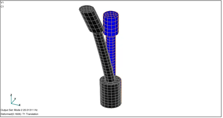
The first mode of spatial model of current transformer is shown in Fig.2. The respective eigen frequencies are given in Table 1.
X Y Z X Y Z V1 C1
Output Set: Mode 2 20.01311 Hz Deformed(0.1606): T1 Translation
Fig. 2 Current transformer - spatial model, mode 1
Table 1. Eigen frequencies, current transformer, spatial model without soil-structure interaction
№ Mode 1 2 3 4 5
Frequency (Hz) 19,90 20,01 65,83 65,85 91,66
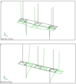
In Fig.3 are illustrated the first and the second mode for FE model of 3 current transformers mounted on a steel frame - supporting structure type 2, taking into account the soil-structure interaction. The respective eigen frequencies are given in Table 2.
X Y Z
X Y Z V1 C1
Output Set: Mode 1 5.365244 Hz Deformed(0.5097): Total Translation
X Y Z
X Y Z V1 C1
Output Set: Mode 2 6.739465 Hz Deformed(1.007): Total Translation
Fig. 3 Three current transformers mounted on second type supporting structure, first and second mode
Table 2. Eigen frequencies, three current transformers mounted on second type supporting structure, taking into account the soil-structure interaction
№ Mode 1 2 3 4 5
Frequency (Hz) 5,365 6,739 9,5 9,704 20,29
The dynamic analysis is conducted using the STARDYNE computer code and the spectral method. The first 50 modes are taken, combined with SRSS rule.
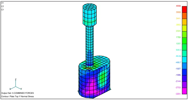
For every case the maximum forces and stresses in the transformer elements are evaluated - Fig.4. The most vulnerable cross section is the lower part of the porcelain isolator. The strength capacity of the porcelain insulator is checked, also the thickness of the lower zone and the anchorage at the base of the transformer. The usual practice up to now is to
wheels are attached to the transformers additional fixing devices are designed (Fig.9), which prevent the possible overturn of the transformers at seismic excitation.
X Y
Z
4558.
3999.
3441.
2882.
2324.
1765.
1207.
648.3
89.82
-468.7
-1027.
-1586.
-2144.
-2703.
-3261.
V1
L3
C1
Output Set: 3.COMBINED FORCES
Contour: Plate Top Y Normal Stress
Fig. 4 Combined transformer - distribution of the normal stresses (compressive zone)
SEISMIC QUALIFICATION BY SEISMIC TEST
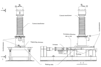
The transformer is qualified by test over a vibration platform (shaking table) in the “Laboratory for studding and surveying of metal structures” at “University for Architecture, Building and Geodesy”, Sofia. A scheme of the shaking table is shown in Fig. 5. Several accelerometers are located at the base of the transformer, at the lower part of the porcelain isolator and at the top of the structure. The testing of the three type of transformers is shown in figures 6,7 and 8. The seismic tests are done using generated accelerograms. They correspond with the review response spectra which are calculated using the finite element models.
The review response spectra are evaluated as a envelop covered the following spectra:
• enveloped response spectrum at the level of upper foundation edge (it is used for checks at Type 1 supporting structure);
• response spectrum, calculated for the level of anchorage of 3 transformers at Type 2 supporting structure (steel frame);
• response spectrum, calculated for the level of anchorage of transformer at Type 3 supporting structure (reinforced concrete column).
The shaking table is moved by hydraulic actuators, produced by INSTRON Ltd. Great Britain. The measurement system is produced by "Hottinger Baldwin Messtechnik" - Germany.
The seismic test is carried out in both horizontal and vertical directions separately. The results of the test can be summarized:
1. There are not detected any mechanical damages or strain of the units after the laboratory tests;
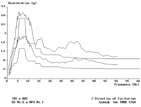
2. The testing response spectra (TRS) fully covered the review response spectra (RRS), accordingly with requirements of the standards [2,3,4] - Fig. 10 and Fig.11.
It can be concluded that the transformers are successfully qualified.
Fig. 5 Shaking table and accelerometers location
Fig. 8 Testing of combined transformer Fig. 9 Additional fixing devices for wheels
Fig. 10 Covering of the review response spectra for horizontal direction - current t-r
Fig.11 Covering of the review response spectra for vertical direction - current t-r
CONCLUSION
Seismic analyses are carried out to qualify three types of electric transformers, produced by Hyundai Heavy Industries Co., Bulgaria. The transformers are mounted on different supporting structures - steel frame structure, reinforced concrete column or directly on foundation at the ground surface level. Three dimensional finite element models are developed including the transformers, supporting structure and soil.
The three types of transformers are qualified for a maximum seismic excitation in the Republic of Bulgaria – IX degree of seismic intensity. The soil conditions are not fixed for the particular site that is why the soil characteristics are varied.
As a result from the analytical investigation is established that there is real danger of overturning of transformers at seismic excitation. Additional fixing devices are designed to fix the wheels against rotation and overturning.
Experimental investigation is performed on the shaking table. All transformers are kept their structural integrity during and after the seismic tests. After the seismic excitation the core and fixing of the transformers were reviewed. There are not founded any damages and distortions. Following the standard requirements the transformers are connected again and successfully pass all the control checks.
REFERENCES
1. STARDYNE, TITAN corporation.
2. US Nuclear Regulatory Commission, Regulatory Guide 1.100, Seismic Qualification of Electric and Mechanical Equipment for Nuclear Power Plants, 1988.
3. IEEE Std 344-1987 Recommended Practice for Seismic Qualification of Class1E Equipment for Nuclear Power Generating Stations.
4. International Standard CEI/IEC 980-1989 Recommended Practice for Seismic Qualification of Electrical Equipment for Nuclear Generating Stations.
ACKNOWLEDGEMENTS
The author gratefully acknowledge the contributions of eng. O.Ganchev and eng. V.Gurov from Laboratory for studding and surveying of metal structures at University for Architecture, Building and Geodesy- Sofia. for performing the seismic tests.