ALKALI AGGREGATE REACTION IN NUCLEAR CONCRETE
STRUCTURES: PART 3: STRUCTURAL SHEAR WALL ELEMENTS
F. Habibi1, S. A. Sheikh1, N. Orbovic2, D. K. Panesar1*and F. J. Vecchio1
1 Professor Department of Civil Engineering, University of Toronto, Toronto, Ontario, Canada 2
Technical Specialist, CNSC-CCSN, Canada ([email protected])
*Corresponding Author ([email protected])
ABSTRACT
The experimental structural part of the program is focused on testing of steel-reinforced walls made with ASR concrete and evaluating their performance against similar walls made with normal concrete. A total of six walls were constructed, four made with ASR concrete and two with normal concrete. All the walls and accompanying small specimens such as cylinders and prisms were conditioned in the same environment in an especially-constructed high temperature and high humidity chamber to accelerate the reaction and deterioration. This paper presents results from structural testing of two walls, one made with ASR concrete and the other regular concrete. The walls were tested under lateral displacement excursions while simultaneously subjected to axial load simulating seismic loads.
INTRODUCTION
Alkali-Aggregate Reaction (AAR) problem is common in many structures such as bridges, roadways, airport runways, and nuclear power plants. As an example, the licence extension of Seabrook Station nuclear power plant is delayed by United States NRC because of the discovery of concrete degradation due to AAR in four buildings (NRC Safety Evaluation Report, 2012).
The Alkali-Aggregate Reaction progresses with time in concrete between the alkaline cement paste and reactive amorphous silica. The reaction uses the moisture in the atmosphere and produces a gel that keeps dilating. The dilating gel causes cracks in the concrete mass thus possibly compromising the integrity of concrete. This can cause a number of issues with regard to the performance of the concrete structures caused by deteriorating concrete properties such as lowering of tensile strength and stiffness and deterioration of bond characteristics.
EXPERIMENTAL PROGRAM
Six wall specimens and a large group of control specimens were cast using two different types of concrete, one containing reactive aggregate (ASR Concrete) and the other normal aggregate (Regular Concrete). Control specimens included 21 cylinders, 3 Modulus of Rupture prisms, three expansion prisms, and three Dog-Bone specimens for each type of the concrete mix used. The concrete mix design for the shear wall and the control specimens were according to the ASTM C1293 (2008). Thus the coarse aggregate was sieved and graded to meet the gradation requirement as per ASTM C1293 (2008).
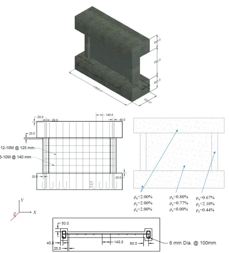
The geometry and the reinforcement of the six shear walls were identical and similar to those of the wall specimens tested by Bouchon et al (2004). Each wall specimen contained two columns as boundary elements as well as two beams, one at the top and the other at the bottom of the wall. The shear wall element of the specimen was reinforced in both vertical and horizontal direction with reinforcement ratio of 0.77% and 0.80%, respectively. Both beams and the boundary elements were designed with high reinforcement ratio to ensure that no premature failure occurred in these elements before the shear wall failure. The reinforcement details also ensured that the failure did not happen in shear-friction at the interface between the wall and the beams. See Figure 1 for a schematic of the shear wall specimen. Table 1Error! Reference source not found. provides relevant properties of the reinforcing steel used in the shear wall specimens. Table 2 shows the concrete mix design for both regular and ASR concretes as received from the supplier.
Table 1: Properties of Steel Bars
Rebar type
Area As (mm2)
Yield strength fy (MPa) Ultimate strength fu (MPa) Strain hardening Strain εsh ultimate strain εu Elastic modulus Es (MPa)
10M 100 430 638 8,000 150,000 182,000
20M 200 465 550 15,000 200,000 190,000
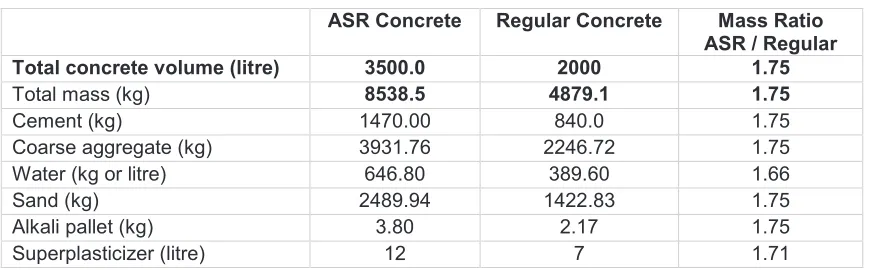
Table 2: Concrete Mix Design
ASR Concrete Regular Concrete Mass Ratio ASR / Regular
Total concrete volume (litre) 3500.0 2000 1.75
Total mass (kg) 8538.5 4879.1 1.75
Cement (kg) 1470.00 840.0 1.75
Coarse aggregate (kg) 3931.76 2246.72 1.75
Water (kg or litre) 646.80 389.60 1.66
Sand (kg) 2489.94 1422.83 1.75
Alkali pallet (kg) 3.80 2.17 1.75
Figure 1: Specimen’s geometry and reinforcement details (dimensions are in mm)
50°C with relative humidity of 95%. Strains of internal reinforcements in the shear wall specimens were monitored and measured monthly. Many of the strain gauges did not seem to show accurate measurements likely due to high temperature and high humidity. In general, the walls with ASR aggregate showed higher strains than normal concrete walls. For example, after six months of being in the chamber, the maximum strain measured from the horizontal steel in the regular concrete walls is about 0.0049 while it is over 0.0072 in walls with ASR concrete. Similarly, the maximum strain in the vertical bars was measured to be 0.0036 and 0.0066 in the regular and ASR walls, respectively.
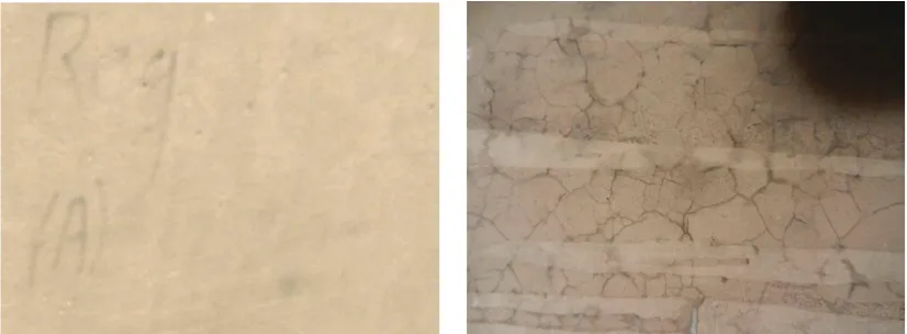
It was decided to test the shear walls in two phases; moderate damage phase and severe damage phase. Moderate damage is referred to as the stage of damage where ASR cracks on the specimens can be identified by visual inspection. Before conducting the structural tests for the first phase, surface of the shear wall specimens were polished to clearly illustrate any cracks due to ASR. As seen in Figure 2 the shear wall specimen containing reactive aggregate showed significant signs of ASR reaction which included alkali spots over the specimen’s surface along with map cracking and silica gel. On the other hand, the shear wall specimen constructed with regular concrete showed none of the above mentioned signs and had a very smooth and fine surface as shown in Figure 2.
Results from physical observations and monitoring of the specimens indicated that the first phase of structural testing could initiate in about 6 months after conditioning of the specimens in the curing chamber. For the first phase, two shear walls, one Regular and one ASR along with some of their control specimens were due for the structural testing.
TESTING
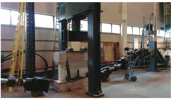
The ultimate capacity of the shear walls was predicted to be in the range of 1,200 kN based on the analysis using VecTor2 software. One actuator of 1,000 kN capacity was thus not suitable for testing. A larger actuator of 2,000 kN capacity was available but its use required extensive preparatory work that could have delayed testing significantly. It was thus decided to use two 1,000 kN actuators, one on each side of the wall specimen. Each actuator was supported by a custom built frame at one end and a small hydraulic jack placed at middle point of the actuator. This support system allowed the actuator to move freely to allow shear deformation of the specimen (Figure 3). To apply the axial force on the walls, a third frame was installed around the specimen holding another hydraulic jack as shown in Error! Reference source not found.4. This jack was used to maintain a constant axial load of 800 kN throughout the test. The shear wall specimen was anchored to the floor, and restrained from both side to prevent any slippage.
Seven LVDTs were used to measure the horizontal displacement along the height of the specimen from bottom beam to the top beam on both sides of the specimen. The Force – Displacement plot was obtained using the summation of the forces from both actuators against displacement of top of the shear wall (bottom of the top beam) with respect to the top of the lower beam.
Figure 3: Schematic drawing showing the test setup for shear walls
Figure 4: Test setup of a shear wall showing the top frame and loading beam
The specimens were loaded using the two actuators working simultaneously. The rate of loading began with 0.005 mm/sec and was increased to a maximum of 0.15 mm/sec as cycles progressed. The first two cycles applied 0.2 mm lateral displacement in the plane of the wall in each direction and the subsequent cycles were at maximum displacements of 0.4, 0.6, 0.8, 1, 1.4, 1.8, 2, 2.5, 3, 4, 4.5, 5.5, 6, and 7 mm. For each displacement two complete cycles were applied. For the Regular shear wall, after completing 2 cycles at 7 mm, the load was increased monotonically until the wall could not maintain the axial load of 800 kN which happened at a displacement of 8.2 mm. In the case of the ASR wall, the specimen was pushed in one direction by 7 mm in the first cycle and then in the opposite direction. During this part of the cycle, the axial load started to drop as the lateral displacement increased and needed constant increase in load. At 7 mm displacement, it was decided to continue load monotonically and at 7.1 mm, the wall failed to maintain the axial load. The test was terminated at that point.
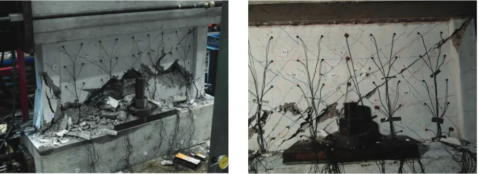
In the Regular concrete specimen, the first cracks appeared on the shear wall at displacement of about 1.4 mm. These cracks had a width of up to 0.4 mm. As cycles progressed, width of these cracks increased and more new cracks were introduced in the shear wall. Cracks on the columns were noticed at a displacement of about 3.5 mm. At 5.5 mm displacement, a huge crack was observed in the columns and at 6 mm displacement, spalling of concrete in column areas was observed. Within this cycle significant spalling of concrete on shear wall panel was noticed accompanied by a diagonal crack which became wider as displacement was increased. The wall carried the maximum load at about 7 mm deflection beyond which it showed a softening response while still maintaining the 800 kN applied axial load and lost its capacity at a displacement of about 8.2 mm. Figure 5 shows the Regular shear wall at failure.
The ASR shear wall specimen cracked initially at a displacement of about 1 mm. These cracks had widths of 0.1 mm to 0.3 mm. As displacement was increased, more cracks opened up along with a noticeable diagonal crack within the shear wall panel. No spalling of concrete was noticed on the shear wall. However, spalling of the concrete in the column area was observed at 6 mm displacement. At this stage the diagonal crack in the wall opened significantly and eventually the specimen failed to maintain the axial load when the lateral displacement was 7.1 mm. The specimen did not display any significant descending branch of the response. See Figure 5 for the ASR shear wall at failure.
Figure 5: Regular shear wall (Left) and ASR shear wall (Right) at failure
Figure 6: Lateral Load vs. Deflection
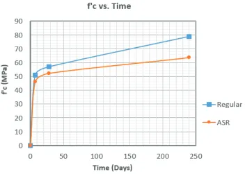
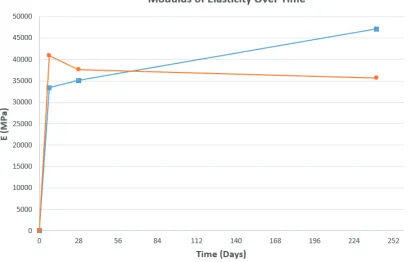
The mechanical properties of the concretes used in both Regular and ASR shear walls were obtained by various testing methods such a direct tensile test, simple beam with third-point loading, and standard cylinder test. Figure 7 illustrates the results from standard cylinder test of both Regular and ASR cylinders over time. The modulus of elasticity of the concrete was also measured based on the stress-strain curves obtained from the compressive strength test of cylinders. Results from this test is shown in Figure 8.
Figure 8: Modulus of Elasticity of Regular and ASR cylinders over time
Error! Reference source not found.Table 3 summarizes information regarding the mechanical properties of the concretes used in the two tested shear walls just before walls were tested. For this phase of tests, the age of Regular and ASR wall specimens were about 240 and 260 days respectively of which they were stored in the acceleration chamber for 210 days.
Table 3: Mechanical Properties of the concrete used in shear walls
Specimen
Compressive Strength
f’c (MPa)
Tensile Strength
(MPa)
Modulus of Rupture
(MPa)
Modulus of Elasticity
(MPa)
Regular 79.0 4.76 7.26 47150
ASR 63.7 3.24 4.64 35750
DISCUSSION
0 1 2 3 4 5 Direct Tensile Strength (MPa)
REG
ASR
0 1 2 3 4 5 6 7 8 Modulus of Rupture (MPa)
REG
ASR
0 10000 20000 30000 40000 50000 Modulus of Elasticity (MPa)
REG
ASR
0 0.05 0.1 0.15 0.2 Concrete Prisms Expansion (Length Change %)
REG
ASR
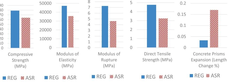
On the other hand, results from the control specimens showed that the modulus of elasticity, modulus of rupture, and direct tensile strength of the regular concrete kept increasing over time while same properties in ASR concrete were reduced beyond a certain age while its compressive strength still increased. Figure 9 compares various properties of the two concretes used in the walls at the age of 240 days.
Figure 9: Comparison of Mechanical Properties of Regular and ASR Concrete at 240 Days
Based on the results from structural testing and control specimens, it is believed that confinement played a critical role in determining the behaviour of ASR wall. In both walls, the top and bottom beams along with the two side boundary elements (columns), induced confinement in the specimens during testing. In the ASR specimen, this confinement was further enhanced due to the restraint developed as a result of expansion of concrete. As the shear wall panel is restrained from all sides, the internal expansion of concrete due to ASR will add significantly to the confinement effect. Since expansion of ASR concrete occurs during curing and conditioning, the reinforcement in the shear wall will undergo a pre-stressing state thus resulting in a stiffer wall response compared with that of Regular concrete wall.
These two factors are most likely responsible for the increase in the ultimate strength and increased initial stiffness of the ASR specimen compared with the Regular wall. The mode of failure is also accordingly affected differently by the state of confinement in both walls.
CONCLUDING REMARKS
In the first testing phase of the study, the behaviour of shear wall affected by Alkali Silica Aggregate was investigated. Two shear walls, one Regular and one ASR were constructed and tested in the Structures Laboratories of the University of Toronto under lateral displacement excursions while simultaneously subjected to axial load simulating seismic loads. Observations from the tests showed that there are several factors that affect the structural performance of the wall specimens. It was found that factors such as confinement and pre-stressing of reinforcement due to ASR expansion resulted in ultimate capacity of the ASR shear wall to be about 14% higher than that of the regular shear wall specimen. However, failure in ASR shear wall was more sudden than that of the regular wall.
Results from control material specimens showed that ASR concrete gains strength over time at slower rate in comparison with Regular concrete. However, the modulus of elasticity and tensile strength in ASR
0 10 20 30 40 50 60 70 80 90 Compressive Strength (MPa)
concrete depreciated significantly with time beyond a certain age while the same properties in the Regular concrete kept increasing. These results indicate that most concrete codes such as ACI and CSA, if applied to ASR concrete, will not accurately capture its mechanical behaviour and properties. In these and other codes, most of the mechanical properties of concrete including the elastic modulus and the tensile strength are obtained through compressive strength of the concrete. Therefore, a different approach will be developed to capture the mechanical properties of concretes affected by ASR.
ACKNOWLEDGEMENTS
The research presented here was supported by the financial support provided by the Canadian Nuclear Safety Commission. The experimental work was conducted in the Structures Laboratories of the University of Toronto. Technical assistance from the lab staff is gratefully acknowledged.
REFERENCES
ASTM Standard C1293-08b, "Standard Test Method for Determination of Length Change of Concrete Due to Alkali-Silica Reaction.
Bouchon, M., Orbovic, N., Foure, B., Tests on Reinforced Concrete Low-Rise Shear Walls under Static Cyclic Loading, 13 WCEE, Vancouver, Canada, August 1 to 5, 2004
Gautam, B., et al. (2015). “Alkali Aggregate Reaction in Nuclear Concrete Structures: Part 2: Concrete Materials Aspects”, submitted to SMiRT23, Manchester, U.K.
Jurcut, A. C., et al. (2015). “Alkali Aggregate Reaction in Nuclear Concrete Structures: Part 4: Modelling and Analysis”, submitted to SMiRT23, Manchester, U.K.
Orbovic, N. et al. (2015). “Alkali Aggregate Reaction in Nuclear Concrete Structures: Part 1: A Holistic Approach”, submitted to SMiRT23, Manchester, U.K.