555-024-402
Comcode 107748717
Issue 1
October 1996
All Rights Reserved Issue 1
Printed in U.S.A. October 1996
Notice
Every effort was made to ensure that the information in this book was complete and accurate at the time of printing. However, information is subject to change.
Your Responsibility for Your System’s Security
Toll fraud is the unauthorized use of your telecommunications system by an unauthorized party, for example, persons other than your company’s employees, agents, subcontractors, or persons working on your company’s behalf. Note that there may be a risk of toll fraud associated with your telecommunications system, and if toll fraud occurs, it can result in substantial additional charges for your telecommunications services.
You and your system manager are responsible for the security of your system, such as programming and configuring your equipment to prevent unauthorized use. The system manager is also responsible for reading all installation, in-struction, and system administration documents provided with this product in order to fully understand the features that can introduce risk of toll fraud and the steps that can be taken to reduce that risk. Lucent Technologies does not warrant that this product is immune from or will prevent unauthorized use of common-carrier telecommunication ser-vices or facilities accessed through or connected to it. Lucent Technologies will not be responsible for any charges that result from such unauthorized use.
Federal Communication Commission (FCC) Statement
This equipment has been tested and found to comply with the limits for a Class A digital device, pursuant to Part 15 of the FCC Rules. These limits are designed to provide reasonable protection against harmful interference when the equipment is operated in a commercial environment. This equipment generates, uses, and can radiate radio frequen-cy energy and, if not installed and used in accordance with the instruction manual, may cause harmful interference to radio communications. However, there is no guarantee that interference will not occur in a particular installation. For further FCC information, see “Customer Support Information” below.
Trademarks
DEFINITY, UNIX, AUDIX, DIMENSION, MERLIN, and PARTNER are registered trademarks of Lucent Technologies in the US and other countries.
Ordering Information
Call:Lucent Technologies Fulfillment Center
Voice 1 800 457-1235International Voice 317 361-5353 Fax 1 800 457-1764International Fax 317 361-5355
Write:Lucent Technologies Fulfillment Center P.O. Box 4100
Crawfordsville, IN 47933
Order:Document No. Lucent Technologies 555-024-402 Comcode 10774877
Issue 2, July 1996
For more information about Lucent Technologies documents, refer to the section entitled “Related Documents” in “About This Book.”
Support Telephone Number
In the continental US, Lucent Technologies provides a toll-free customer helpline 24 hours a day. Call the Lucent Technologies Helpline at 1 800 242-2121 or your Lucent Technologies authorized dealer if you need assistance when installing, programming, or using your system. Outside the continental US, contact your local Lucent Technologies representative.
Lucent Technologies Fraud Intervention
If you suspect you are being victimized by toll fraud and you need technical support or assistance, call the BCS Tech-nical Service Center at 1 800 643-2353 or 1 800 242-2121.
Warranty
User’s Guide 555-024-402 October 1996 Contents
Page iii
Contents
Contents iii
Customer Support Information xi
■ Support Telephone Number xi
■ Security of Your System: Preventing Toll Fraud xii ■ Lucent Technologies Fraud Intervention xiii
■ Guarantee xiii
RPSD Lock with no Keys xiii
RPSD Lock with Keys xiv
■ Limited Warranty xv
■ FCC Notification and Repair Information xvi ■ Installation and Operational Procedures xvii ■ Federal Communication Commission
(FCC) Electromagnetic Interference
Information xviii
About This Book xix
■ Intended Audiences xix
■ Responsibilities xix
■ Terms and Conventions xx
■ Typographical Conventions xxi
■ How to Use This Book xxi
■ Product Safety Labels xxii
■ Related Documents xxii
■ How to Comment on This Document xxii
1
Introduction 1-1■ RPSD System 1-2
■ Hardware Components 1-5
RPSD Lock 1-5
RPSD Key 1-7
Modems 1-8
RPSD Lock or Key Administration Terminal 1-9
RPSD Lock Administration Printer 1-9
■ Software Components 1-10
■ System Administration 1-11
User’s Guide 555-024-402 October 1996 Contents
Page iv
System Activity Log 1-12
Single Point Administration 1-14
Block Lucent Technologies and Other Key Users 1-15
Force Connect/Disconnect 1-15
Authorized Keys 1-16
2
Installation 2-1■ Room Layout/Environment 2-2
Power Supply 2-2
Location of Administration Terminal or Printer 2-3
■ Installation 2-4
Cables, Connectors, and Ports 2-5
Installing the RPSD Lock 2-5
Installing the RPSD Key 2-16
Testing an Uninitialized Key 2-18
Initializing the RPSD Lock 2-18
Initializing the RPSD Key 2-19
■ Testing the RPSD Lock Installation 2-20
3
RPSD System Administration 3-1■ Menu of Commands 3-2
■ Command Functions 3-5
A—Add User 3-6
AH—Access History 3-11
AA—Administrative Access History 3-14
AF—Administrative Failure History 3-17
AS—AUX Security 3-19
B—Block User 3-21
CR—Change Restriction 3-22
C—Clock Set 3-24
D—Date Set 3-25
FH—Failure History 3-26
FC—Force Connect 3-29
FD—Force Disconnect 3-30
I—ID Set 3-31
LR—List Restrictions 3-32
User’s Guide 555-024-402 October 1996 Contents
Page v
L—List User Table 3-36
LH—Log History 3-40
Q—Quit 3-44
R—Remove User 3-45
RS—Reset Statistics 3-46
SC—Set Communications Parameters 3-47
ST—Status Display 3-48
T—Test User 3-50
U—Unblock User 3-51
UR—User Restrictions 3-52
Help Screens 3-54
4
Key Administration and Use 4-1■ RPSD Key User Command Set 4-2
■ Initialization Functions 4-3
U—Set User ID 4-3
K—Set Secret Key 4-4
N—Set Device Number 4-5
■ Command Functions 4-6
A—Add Administrative User 4-7
AS—AUX Security 4-9
C—Clock Set 4-10
D—Date Set 4-11
H—History Display 4-12
I—Set Log ID 4-14
L—List User Information 4-15
LA—List Administrative Users 4-16
Q—Quit 4-17
R—Remove Administrative User 4-18
S—Status Display 4-19
SC—Set Communications Parameters 4-20
W—Wipe Out 4-21
?—Help 4-22
■ Authentication 4-23
Password Authentication 4-23
User’s Guide 555-024-402 October 1996 Contents
Page vi
5
Troubleshooting 5-1■ Access Failure Messages. 5-2
■ Testing the RPSD Lock 5-6
Built-in Diagnostics 5-6
Hardware Replacement 5-9
■ Replacing the RPSD Lock or Key 5-10
■ Saving the Key Seed Value 5-11
A
Cables, Connectors, and Ports A-1B
Front Panel LEDs B-1■ RPSD Lock B-2
User’s Guide 555-024-402 October 1996
Page ix
When installing telephone equipment, always follow basic safety precautions to reduce the risk of fire, electrical shock, and injury to persons, including:
■ Read and understand all instructions.
■ Follow all warnings and instructions marked on or packed with the
product.
■ Never install this unit or telephone wiring for it during a lightning storm.
■ Never install a telephone jack in a wet location unless the jack is
specifically designed for wet locations.
■ Never touch uninsulated telephone wires or terminals unless the
telephone wiring has been disconnected at the network interface.
■ Use caution when installing or modifying telephone lines.
■ Use only Lucent Technologies-manufactured circuit packs, carrier
assemblies, and power units in the control unit.
■ Use only Lucent Technologies-recommended/approved accessories.
■ Do not install this product near water, for example, in a wet basement
location.
■ Do not overload wall outlets, as this can result in the risk of fire or
electrical shock.
■ Do not attach the power supply cord to building surfaces. Do not allow
anything to rest on the power cord. Do not locate this product where the cord will be abused by persons walking on it.
■ Unplug the product from the wall outlet before cleaning. Use a damp cloth
for cleaning. Do not use cleaners or aerosol cleaners.
■ Do not operate the system if chemical gas leakage is suspected in the
area. Use telephones located in some other safe area to report the trouble.
!
WARNING:
DO NOT open the RPSD Lock or Key devices. There are no user serviceable parts inside the units. Only an authorized technician should open a unit for required maintenance or upgrading purposes.
SAVE THESE INSTRUCTIONS
The exclamation point in an equilateral triangle is intended to alert the user to the presence of important operating and maintenance (servicing) instructions in the literature accompanying the product.
User’s Guide 555-024-402 October 1996
Customer Support Information
Page xi Support Telephone Number
User’s Guide 555-024-402 October 1996
Customer Support Information
Support Telephone Number
In the USA only, Lucent Technologies provides a toll-tree customer Helpline,
1 800 242-2121, 24 hours a day. If you need assistance when installing, programming, or using your system, call the Helpline, or your Lucent Technologies authorized representative.
User’s Guide 555-024-402 October 1996 Customer Support Information
Page xii Security of Your System: Preventing Toll Fraud
Security of Your System: Preventing
Toll Fraud
As a customer of a new communications device, you should be aware that there is an increasing problem of telephone toll fraud. Telephone toll fraud can occur in many forms, despite the numerous efforts of telephone companies and
telephone equipment manufacturers to control it. Some individuals use electronic devices to prevent or falsify records of these calls. Others charge calls to someone else’s number by illegally using lost or stolen calling cards, billing innocent parties, clipping on to someone else’s line, or breaking into someone else’s telephone equipment physically or electronically. In certain instances, unauthorized individuals make connections to the telephone network through the use of remote access features.
Common carriers are required by law to collect their tariffed charges. While these charges are fraudulent charges made by persons with criminal intent, applicable tariffs state that the customer of record is responsible for payment of all long- distance or other network charges. Lucent Technologies cannot be responsible for such charges and will not make any allowance or give any credit for charges that result from unauthorized access.
To minimize the risk of unauthorized access to your communications system or device:
■ When possible, restrict the off-network capability of off- premises callers,
using calling restrictions, Facility Restriction Levels, and Disallowed List capabilities.
■ When possible, block out-of-hours calling.
■ Frequently monitor system call detail reports for quicker detection of any
unauthorized or abnormal calling patterns.
■ Limit outcalling to persons on a need-to-have basis.
The communications system, through proper administration, can help you reduce the risk of unauthorized persons gaining access to the network. However, phone numbers and authorization codes can be compromised when overheard in a public location, lost through theft of a wallet or purse containing access information, or when treated carelessly (writing codes on a piece of paper and improperly discarding them).
Additionally, hackers may use a computer to dial an access code and then publish the information to other hackers. Substantial charges can accumulate quickly. It is your responsibility to take appropriate steps to implement the features properly, to evaluate and administer the various restriction levels, and to protect and carefully distribute access codes.
User’s Guide 555-024-402 October 1996 Customer Support Information
Page xiii Lucent Technologies Fraud Intervention
Lucent Technologies Fraud
Intervention
If you suspect you are being victimized by toll fraud and you need technical support or assistance, call the following:
■ For DEFINITY and Voice Mail products, call the Technical Service Center
(TSC) at 1 800 242-2121.
■ For system 25, MERLIN, and PARTNER products, call the National Service
Assistance Center (NSAC) at 1 800 628-2888.
Guarantee
Lucent Technologies sells the Remote Port Security Device (RPSD) to provide an additional layer of security for the remote administration port on Lucent
Technologies communications systems and other Lucent Technologies BCS products. Lucent Technologies offers the following guarantee for the RPSD on Lucent Technologies communications systems located within the United States.
RPSD Lock with no Keys
If the customer purchases an RPSD Lock with no Keys, Lucent Technologies will pay for unauthorized calls that occur as a result of access to the system via the remote administration port through the RPSD, provided the following conditions are met:
■ The RPSD was installed correctly on the remote administration port on the
Lucent Technologies communications system and configured at the time of the fraud incident to accept only Lucent Technologies Keys.
NOTE:
In this context, correct installation means that the RPSD Lock is installed consistent with installation instructions and in such a way as to deny access in case of power failure.
■ The customer provides RPSD documentation to Lucent Technologies
showing the time of access.
■ The customer provides the communications system history log information
to Lucent Technologies showing the changes made to the system to allow toll fraud at the time shown by the RPSD log.
■ The customer provides telephone records to Lucent Technologies that
indicate the fraud was accomplished via the changes made at that time.
■ The customer provides Lucent Technologies with access to all additional
User’s Guide 555-024-402 October 1996 Customer Support Information
Page xiv Guarantee
RPSD Lock with Keys
If the customer purchases RPSD Keys to access the systems protected by RPSD Locks, Lucent Technologies does not assume responsibility for the use of customer-purchased Keys. Accordingly, Lucent Technologies will pay for the unauthorized calls that occur as a result of access to such systems via the remote administration port through the RPSD provided the following conditions are met:
■ The RPSD Lock was installed correctly on the remote administration port
on the DEFINITY system at the time of the fraud incident.
NOTE:
In this context, correct installation means that the RPSD Lock is installed consistent with installation instructions and in such a way as to deny access in case of power failure.
■ The customer provides RPSD documentation to Lucent Technologies
showing the time of access and that the access was accomplished via a Lucent Technologies ID.
■ The customer provides the communications system history log information
to Lucent Technologies showing the changes made to the system to allow toll fraud at the time shown by the RPSD log.
■ The customer provides telephone records to Lucent Technologies that
indicate the fraud was accomplished via the changes made at that time.
■ The customer provides Lucent Technologies with access to all additional
User’s Guide 555-024-402 October 1996 Customer Support Information
Page xv Limited Warranty
Whether or not the customer uses Keys, the customer agrees to promptly take all necessary steps to stop the toll fraud after becoming aware of it. Lucent
Technologies’ liability under this RPSD guarantee ceases two hours after the customer becomes aware of the toll fraud incident. In no event shall Lucent Technologies’ responsibility exceed the amount of the customer’s payment to the network provider for the unauthorized calls. Lucent Technologies’ liability is limited to the unauthorized calls and does not include consequential damages such as lost profits due to phone lines being unavailable.
Limited Warranty
Lucent Technologies, Inc. warrants this equipment to be free of defects in materials and workmanship for a period of one year from date of shipment. All defects within this time will be repaired without charge upon return of the unit to the factory.
This warranty is null and void if the manufacturer determines that any modifications have been made to the unit or the unit has been subjected to physical or electrical stress.
This warranty covers parts and labor only and does not include shipping costs, travel expenses, or travel time.
Installation of the equipment is the sole responsibility of the purchaser. The manufacturer, its agents, or its distributors accept no responsibility for
malfunction or damage caused by improper treatment or connection of the unit.
The manufacturer, its agents, or its distributors are not liable for any losses incurred through use or malfunction of the equipment or any losses or damages incurred by the use of the equipment in any means whatsoever.
This warranty is limited to the repair of the equipment to its normal functioning capability.
User’s Guide 555-024-402 October 1996 Customer Support Information
Page xvi FCC Notification and Repair Information
FCC Notification and Repair
Information
This equipment is registered with the FCC in accordance with Part 68 of its rules. In compliance with those rules, you are advised of the following:
■ Means of Connection. Connection of this equipment to the telephone
network shall be through a standard network interface jack, USOC RJ11C. These USOCs must be ordered from your telephone company.
■ Party Lines and Coin Telephones. This equipment can not be used with
party lines or coin telephone lines.
■ Notification to the Telephone Companies. Before connecting this
equipment, you or your equipment supplier must notify your local telephone company’s business office of the following:
— The telephone number(s) you will be using with this equipment.
— The appropriate registration number and ringer equivalence number (REN), which can be found on the back or bottom of the control unit.
— For each jack, the sequence in which lines are to be connected, the line types, the Facility Interface Code (FIC), and the Ringer
Equivalence Number (REN) by position when applicable.
■ Ringer Equivalence Number (REN). The REN is used to determine the
number of devices that can be connected to the telephone line. Excessive RENs on the line can result in the devices not ringing in response to an incoming call. In most, but not all, areas the sum of the RENs should not exceed five (5.0). To be certain of the number of devices that can be connected to the line, as determined by the total RENs, contact the local telephone company to determine the maximum REN for the calling area.
■ Disconnection. You must also notify your local telephone company if and
User’s Guide 555-024-402 October 1996 Customer Support Information
Page xvii Installation and Operational Procedures
Installation and Operational
Procedures
This manual contains information about installation and operational procedures.
■ Repair Instructions. If you experience trouble because your equipment is
malfunctioning, the FCC requires that the equipment not be used and that it be disconnected from the network until the problem has been corrected. Repairs to this equipment can be made only by the manufacturers, their authorized agents, or others who may be authorized by the FCC. In the event repairs are needed on this equipment, contact your authorized Lucent Technologies dealer or, in the USA only, contact the National Service Assistance Center (NSAC) at 1 800 242-2121.
■ Rights of the Local Telephone Company. If this equipment causes harm to
the telephone network, the local telephone company may discontinue your service temporarily. If possible, they will notify you in advance. But if advance notice is not practical, you will be notified as soon as possible. You will also be informed of your right to file a complaint with the FCC.
■ Changes at Local Telephone Company. Your local telephone company
may make changes in its facilities, equipment, operations, or procedures that affect the proper functioning of this equipment. If they do, you will be notified in advance to give you an opportunity to maintain uninterrupted telephone service.
■ New Network Area and Exchange Codes. The communications system
software does not restrict access to any new area codes or exchange codes established by a local telephone company. If the user has
established toll restrictions on the system that could restrict access, then the user should check the lists of allowed and disallowed dial codes and modify them as needed.
■ Equal Access Codes. This equipment is capable of providing users
User’s Guide 555-024-402 October 1996 Customer Support Information
Page xviii Federal Communication Commission (FCC) Electromagnetic Interference Information
Federal Communication Commission
(FCC) Electromagnetic Interference
Information
This equipment has been tested and found to comply with the limits for a Class A digital device, pursuant to Part 15 of the FCC Rules. These limits are designed to provide reasonable protection against harmful interference when the equipment is operated in a commercial environment. This equipment generates, uses, and can radiate radio frequency energy and, if not installed and used in accordance with the instruction manual, may cause harmful interference to radio
About This Book
Page xix Intended Audiences
User’s Guide 555-024-402 October 1996
About This Book
Intended Audiences
This document is intended for the following audience:
■ Lucent Technologies technicians
■ RPSD system administrators
■ RPSD Key users
Lucent Technologies technicians are the personnel from Lucent Technologies who install the Remote Port Security Device (RPSD) Lock at the customer premises. It is assumed that Lucent Technologies technicians are familiar with the technical language used to describe the hardware components, cables, connectors, and ports involved in the installation of the RPSD Lock. It is further assumed that they will have the tools and equipment necessary for installation.
RPSD system administrators are the customer personnel who administer and maintain the RPSD Lock. It is assumed that RPSD system administrators are familiar with menu-driven telecommunications hardware components. It is also assumed that they understand the need for maintaining security in administering the communications system.
RPSD Key users are those who dial in to a channel locked with a Lock by using a Key. It is assumed that Key users are familiar with placing calls via a modem, either from a telephone, terminal, or PC.
Responsibilities
User’s Guide 555-024-402 October 1996 About This Book
Page xx Terms and Conventions
RPSD Keys purchased by the customer can be installed by Lucent Technologies technicians at the customer’s request or installed by the customers.
The troubleshooting material in this document may be used by the technician at the time of installation, but it is written primarily for the customer. Failure of any Lock or Key is always resolved by replacement of the failed device.
The Lock commands and administration material is written for RPSD system administrators. The material on Key commands and use is written for Key users.
Supplying equipment peripheral to the Lock, such as terminals, modems, printers, etc., is the customer’s responsibility. If any material is required in addition to the material shipped in the RPSD package, it is billable to the customer.
Terms and Conventions
The Remote Port Security Device (RPSD) Lock is often referred to as the Lock. Similarly the RPSD Key is often referred to as the Key.
Throughout this document, toll fraud security hazards are indicated by an exclamation point inside a triangle and the words Security Alert.
!
Security Alert:
User’s Guide 555-024-402 October 1996 About This Book
Page xxi Typographical Conventions
Typographical Conventions
Throughout this manual RPSD system responses are shown in italic, sans serif type. For example:
Call authentication completed
Data that you enter is shown in bold sans serif type. For example:
Block user
The button at the end of the line tells you to press the Enter or Return key to complete the command.
NOTE:
In this document, a remote caller’s computer terminal or personal computer is referred to as the user’s terminal. The local terminal connected to the RPSD Lock is referred to as the system administrator’s terminal or administration terminal.
How to Use This Book
This is organized into chapters that give information on procedures necessary for the proper installation and administration of your Remote Port Security Device.
“Related Documents,” later in this section, provides a complete list of system documentation, together with ordering information.
If you have problems with your RPSD system, contact your system administrator. If the problem cannot be solved by the system administrator, in the continental U.S. your system will call our toll-free Helpline, available 24 hours a day, at 1 800 242-2121. Outside of the continental U.S., contact your Lucent Technologies representative or local authorized dealer.
ENTER
User’s Guide 555-024-402 October 1996 About This Book
Page xxii Product Safety Labels
Product Safety Labels
Throughout these documents, hazardous situations are indicated by an exclamation point inside a triangle and the word caution or warning.
!
WARNING
:
Warning indicates the presence of a hazard that could cause death or severe personal injury if the hazard is not avoided.
!
CAUTION
:
Caution indicates the presence of a hazard that could cause minor personal injury or property damage if the hazard is not avoided.
Related Documents
In addition to this book, the document listed below is part of the documentation set. Within the continental United States, order this document from the BCS Publications Fulfillment Center by calling 1 800 457-1235.
How to Comment on This Document
We welcome your comments, both positive and negative. Please use the feedback form on the next page to let us know how we can continue to serve you. If the feedback form is missing, write directly to:
Documentation Manager Lucent Technologies, Inc. 211 Mount Airy Road Room 2W-226
Basking Ridge, NJ 07920-2332
Document No. Title
User’s Guide 555-024-402 October 1996 About This Book
Page xxiii How to Comment on This Document
FEEDBACK FORM Remote Port Security Device
Title: Remote Port Security Device User’s Guide Order No.: 555-024-402 Date: October 1996
1. Please rate the effectiveness of this book in the following areas:
2. Please check ways you feel we could improve this book:
o Improve the overview o Add more examples o Add troubleshooting information
o Improve the table of contents o Add more detail o Make it less technical
o Improve the organization o Make it more concise o Add more/better quick reference aids
o Include more illustrations o Add more step-by- o Improve the index/glossary step procedures
o Other_____________________________________________________________________________________
___________________________________________________________________________________________
___________________________________________________________________________________________
3. What did you like most about this book?
___________________________________________________________________________________________ ___________________________________________________________________________________________
4. Feel free to write any comments below or on an attached sheet.
___________________________________________________________________________________________ ___________________________________________________________________________________________ ___________________________________________________________________________________________ ___________________________________________________________________________________________
If we may contact you about your comments, please complete the following:
Name: _________________________ _________________________Telephone Number: __________________ Company/Organization: ____________ ________________ ________Date: ______________________________ Address: ____________________________________________________________________________________
Send completed forms to: Documentation Manager, Lucent Technologies, 211 Mount Airy Road, Room 2W226, Basking Ridge, NJ 07920. Fax: (908) 953-6912.
THIS FORM MAY BE PHOTOCOPIED
Excellent Good Fair Poor Not Applicable Ease of Use
User’s Guide 555-024-402 October 1996 About This Book
Introduction
Page 1-1
1
User’s Guide 555-024-402 October 1996
1
1
Introduction
User’s Guide 555-024-402 October 1996 Introduction
Page 1-2 RPSD System
1
RPSD System
The RPSD system provides security and control for virtually any type of dial-up port on any host resource, regardless of the type of modem associated with the host’s dial-up ports. This document specifically targets Lucent Technologies Business Communications Systems customers and users of the communications systems listed below and supporting peripheral products; therefore, most references in this document are specific to Business Communications Systems. However, other applications of the RPSD system are possible.
Lucent Technologies supports RPSD use on the following types of communications systems:
■ System 75 (R1V2, R1V3)
■ System 85 (R1V1, R1V2, R2V1, R2V2, R2V3, R2V4)
■ DEFINITY® Enterprise Communications Server (ECS) (all models)
■ DIMENSION
■ Other communications systems with dial-up ports
■ All voice-mail systems
■ Any product that supports analog tip-and-ring capability.
With the RPSD Lock and Key system you can set the time of day that access to a port is permitted, or you can block any or all access to the line by users of RPSD Keys. In addition, a system activity log provides a real-time record of access attempts and their outcomes. Session summaries track statistics on all successful and failed attempts, providing convenient MIS data resources.
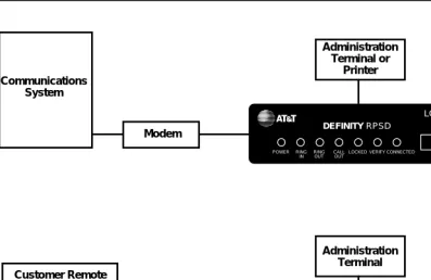
As shown in Figure 1-1, the RPSD Lock is approximately the size of a modem and is connected between the communications system modem and the central office line. The RPSD Key is of similar size and is connected between the caller’s modem and central office line.
NOTE:
In Figure 1-1, the term “Lucent Technologies Remote Operations” refers to Technical Services Center remote administration and maintenance
User’s Guide 555-024-402 October 1996 Introduction
Page 1-3 RPSD System
1
Figure 1-1. RPSD Lock and Key Configuration
The system administrator administers the RPSD Lock via a direct connection from an administration terminal to the Lock. The administration interface is menu driven.
The RPSD system protects a port in the following manner: a call into the channel to the protected host activates the RPSD Lock. Without involving the protected host resource or its associated modem, the RPSD Lock verifies the caller’s identity by using dual-tone, multifrequency (DTMF) signaling with the RPSD Key. This process is as follows (see Figure 1-1).
1. The Lock, installed on tip and ring on the network side of any modem or protected host resource, answers the incoming call.
2. The Lock sends the caller a polling tone. If the calling party has an RPSD Key, the Key responds with its User ID. If there is no Key on the calling end, the Lock terminates the call.
3. The Lock must recognize the Key’s User ID (the Lock must be previously initialized with all valid Keys); if not, the Lock terminates the call.
4. Using an algorithm governed by ANSI/DES standards, the Lock generates a random 10-digit value (known as the “dynamic challenge,” for which there are 10 billion possible values). Using a secret encryption key unique to the calling RPSD Key’s User ID, the Lock encrypts the value.
DEFINITY RPSD LOCK POWER RING IN RING OUT CALL OUT
LOCKED VERIFY CONNECTED
DEFINITY RPSD KEY POWER RING IN CALL OUT
IDLE VERIFY CONNECTED
User’s Guide 555-024-402 October 1996 Introduction
Page 1-4 RPSD System
1
5. The Lock stores this encrypted “expected value” and sends the dynamic challenge to the Key.
6. When the Key receives the challenge from the Lock, it uses the secret encryption key unqiue to the user ID assigned to the Key and encrypts the value the Lock sent. Following this, the Key calculates the necessary response. The Key transmits this “expected value” to the Lock.
7. The Lock compares the Key’s response to the expected value it
calculated and stored. If the Lock receives the precise value it expects, it generates ringing and sends the call on to the protected resource.
User’s Guide 555-024-402 October 1996 Introduction
Page 1-5 Hardware Components
1
Hardware Components
To install a complete RPSD system, you need a Lock and a Key. A
communications system and modem are assumed to be at the customer site already.
NOTE:
Although a printer is not essential to system operation, you should consider dedicating a serial printer to the RPSD Lock. (The printer should be set to 9600 kbps, N, 8, 1.) The System Activity Log can store up to 1400
messages, but the only means of retaining a more permanent record of system activity is either to install a dedicated printer for the RPSD Lock or to save all messages from the Lock to disk.
The Lucent Technologies personnel who require access to the communications system already have the Keys they need. Any additional RPSD Keys for customer use must be ordered separately.
The hardware components (both supplied and otherwise) and their requirements are described in the following sections.
RPSD Lock
When you order the RPSD Lock, you receive:
■ The Lock
■ Power supply
■ 7-foot line cord with RJ11 modular connectors on each end
■ 14-foot line cord with RJ11 modular connectors on each end
■ DB9 (male) to DB25 (female) cable
User’s Guide 555-024-402 October 1996 Introduction
Page 1-6 Hardware Components
1
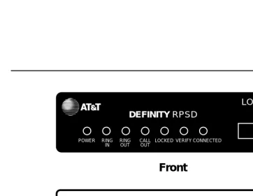
The RPSD Lock is 5.75 inches wide by 9.5 inches long by 1.75 inches high. It has seven LEDs on the front panel and four ports on the back panel (see Figure 1-2). For a detailed description of the front panel LEDs, see Appendix B, “Front Panel LEDs.” The back panel ports are:
■ RJ11 port for the modem connection, labeled SUBSCRIBER
■ RJ11 port for the central office line, labeled TELCO
■ Female DB9 port for the terminal or printer (or a modem), labeled AUX.
PORT
■ Alarm leads to connect an external alarm
■ Port for the power supply (supplied with the RPSD Lock)
Figure 1-2. RPSD Lock
Power Monitor Function
The Power Monitor function allows you to control the behavior of the RPSD during power failure conditions. The POWER MONITOR button on the back of the Lock enables or disables this function.
SUBSCRIBER (MODEM) TELCO
AUX. PORT +
!
12VDC 1A ALARM LEADS
POWER MONITOR RED
GREEN BYPASS SECURE
DEFINITY RPSD
LOCK
POWER RING
IN RINGOUT CALLOUT LOCKED VERIFY CONNECTED
Front
User’s Guide 555-024-402 October 1996 Introduction
Page 1-7 Hardware Components
1
In the event of a unit failure or a power failure, the RPSD blocks incoming and outgoing calls to the port, protecting the port against unauthorized access. This call blocking also prevents the communications system or other protected resources from originating an alarm and blocks dial-up access to the port.
However, you can push in the POWER MONITOR button on the back of the Lock to enable the Power Monitor function. The green LED lights to indicate that the Power Monitor function is enabled. When this function is enabled, the TELCO and SUBSCRIBER ports are connected during a power failure, thereby bypassing the Lock security. This bypassing permits incoming calls to the communications system or other host resource.
!
Security Alert:
When the POWER MONITOR button is IN during a unit or power failure, the security of the RPSD Lock is bypassed. Leave the button in the OUT position for security reasons.
External Alarm
You can connect alarm leads to the screw terminals on the back of the Lock. When a Lock failure occurs, contacts inside the Lock close and send a signal out the alarm terminals to the communications system or other external alarm.
You can also use the Power Monitor function to generate a signal failure through the alarm leads without bypassing the RPSD and compromising security. This is called an Alarm Only installation.
RPSD Key
The RPSD Key is similar to the RPSD Lock in size and appearance. When you order the RPSD Key, you receive:
■ The Key
■ Power supply
■ 7-foot line cord with RJ11 modular connectors on each end
■ 14-foot line cord with RJ11 modular connectors on each end
■ DB9 (male) to DB25 (female) cable
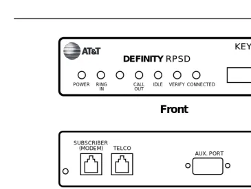
Like the RPSD Lock, the RPSD Key has LEDs on the front panel and ports on the back panel. For a detailed description of the front panel LEDs, see Appendix B, “Front Panel LEDs.” The back panel ports are (see Figure 1-4):
■ RJ11 port for the central office line, labeled TELCO
■ RJ11 port for the modem connection, labeled SUBSCRIBER
■ Female DB9 port for the terminal or printer, labeled AUX. PORT
User’s Guide 555-024-402 October 1996 Introduction
Page 1-8 Hardware Components
1
Install the RPSD Key between the Key user’s central office line and modem.
Figure 1-3. RPSD Key
Modems
The RPSD Lock works with any modem that can be used with the
communications system. Similarly, the RPSD Key works with any modem that can be used with a terminal.
NOTE:
Version 3 of the RPSD Lock and Key works with low- and high-speed modems up to 28.8 kbps. Versions 1 and 2 work only with low-speed modems up to 9.6 kbps.
SUBSCRIBER
(MODEM) TELCO
AUX. PORT +
!
12VDC 1A
Front
Back
DEFINITY RPSD
KEY
POWER RING IN
CALL OUT
User’s Guide 555-024-402 October 1996 Introduction
Page 1-9 Hardware Components
1
RPSD Lock or Key Administration Terminal
The administration terminals for both Lock and Key are customer supplied. Any administration terminal for the RPSD Lock or for the RPSD Key must meet the following requirements:
■ Asynchronous
■ Full or half-duplex
■ Standard RS-232 interface for connection to a DCE interface
■ Baud rate in the range 300–19.2K (19.2K is the maximum rate for the DB9
AUX PORT.)
■ Any word size and parity
Use a standard RS-232 cable to connect the administration terminal to the DB9/DB25 cable connected to the AUX. PORT of the RPSD Lock or Key. This RS-232 cable is not supplied. The AUX. PORT is the same port used if a printer is installed. You may wish to install a switch to make changing the AUX. PORT connection easier (for example, from a terminal to a printer).
The terminal should initially be set to 9600 bps and 8 bits, no parity. These are the factory default settings of the Lock and the Key. You may change these parameters later on Lock, Key, and administration terminals.
RPSD Lock Administration Printer
The RPSD Lock requires a serial printer with XON/XOFF flow control.
User’s Guide 555-024-402 October 1996 Introduction
Page 1-10 Software Components
1
Software Components
User’s Guide 555-024-402 October 1996 Introduction
Page 1-11 System Administration
1
System Administration
The RPSD Lock prevents unauthorized access to the channel used by Lucent Technologies personnel to perform maintenance and/or to administer your communications system. When you administer the RPSD, keep in mind that access via telephone lines is not the only means of breaching the security of your system. A system can be breached, for example, by physically intercepting lines and adding unauthorized equipment. RPSD users may need to take many actions to enhance overall telecommunication security. These actions include, but are not limited to, providing physical security for RPSD installation sites (locked rooms, cabinets, etc.) and wiring room sites. Monitor the RPSD System Activity Log for patterns of activity, such as repeated denied call attempts. Contact your computer security group for assistance.
!
Security Alert:
The Remote Port Security Device, if properly installed and managed, provides a significant and substantial barrier to unauthorized access to a dial-up communication port.
The Remote Port Security Device is not impregnable but is an important addition to the tools and measures used by system managers to prevent unauthorized access to dial-up ports.
Time of Day Access
The RPSD Lock can be administered to prevent access from one or more Key or from all Keys during specified times of day. The default setting is no blockage of access for any Key user at any time. The administrable parameters are time, date, and user ID. Up to 14 separate time restrictions (periods of no access) may be set for any one user ID. Time restrictions may overlap.
For example, you can use this feature to prevent any administration of the communications system while a system administrator is not present to oversee the administration. In this instance, you could administer the Lock to block all users from 6:00 p.m. (18:00 hours using a 24-hour clock format) when the system administrator leaves the office until 8:00 a.m. (08:00 hours using a 24-hour clock format) when the system administrator returns to the office.
User’s Guide 555-024-402 October 1996 Introduction
Page 1-12 System Administration
1
System Activity Log
The System Activity Log retains a log history of the last 500 status messages generated by the Lock. Status messages include a history (including date and time) of the following RPSD system activity:
■ Any RPSD system administration
■ Calls received attempting to access the host resource
■ The outcome of any access attempts (connected or failed)
■ The reason for the failure of call attempts
■ When the call was disconnected
As a new message is generated, the oldest message in the buffer is deleted. The most recent 20 messages are displayed on the first page in real-time on the RPSD Lock administration terminal. That is, the oldest message scrolls off the screen on the administration terminal as the new message is added to the bottom. When a printer is connected to the RPSD Lock administration terminal, each new message is printed at the bottom of the page as it is received from the Lock. This allows you to create a more permanent hard-copy record of status messages.
The messages are numbered consecutively from 000 to 999. If a printer is used, any breaks in this sequence indicate an interruption of log printing.
User’s Guide 555-024-402 October 1996 Introduction Page 1-13 System Administration 1 :
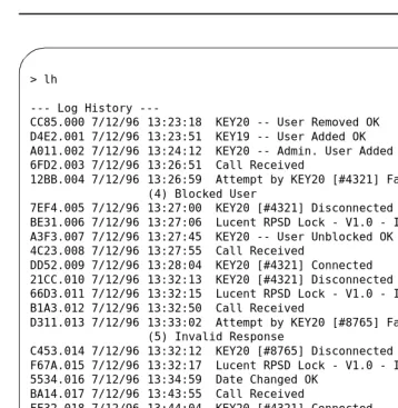
Figure 1-4. Sample Log History
The fields of the System Activity Log entries are:
■ Message Authentication Code/ Sequence Number—The Message
Authentication code generated for each entry on the System Activity Log. The code is generated to protect the integrity of the Log History. The Message Authentication is followed by a period (“.”) and the sequence number of each status message. The messages appear in sequence from 000 to 999 and then restart at 000.
■ Date—The date of the message
■ Time—The time the message was generated in 24-hour clock format
■ Message—The status message
In Figure 1-4, KEY20 is a user ID. Information shown in square brackets is the RPSD user ID number (as in the fifth message in Figure 1-4). Users can be assigned the same user ID; the user ID number provides a second means of identifying the calling party.
> lh
Log History
---CC85.000 7/12/96 13:23:18 KEY20 -- User Removed OK D4E2.001 7/12/96 13:23:51 KEY19 -- User Added OK A011.002 7/12/96 13:24:12 KEY20 -- Admin. User Added OK 6FD2.003 7/12/96 13:26:51 Call Received
12BB.004 7/12/96 13:26:59 Attempt by KEY20 [#4321] Failed (4) Blocked User
7EF4.005 7/12/96 13:27:00 KEY20 [#4321] Disconnected
BE31.006 7/12/96 13:27:06 Lucent RPSD Lock - V1.0 - Idle/Locked A3F3.007 7/12/96 13:27:45 KEY20 -- User Unblocked OK
4C23.008 7/12/96 13:27:55 Call Received
DD52.009 7/12/96 13:28:04 KEY20 [#4321] Connected 21CC.010 7/12/96 13:32:13 KEY20 [#4321] Disconnected
66D3.011 7/12/96 13:32:15 Lucent RPSD Lock - V1.0 - Idle/Locked B1A3.012 7/12/96 13:32:50 Call Received
D311.013 7/12/96 13:33:02 Attempt by KEY20 [#8765] Failed (5) Invalid Response
C453.014 7/12/96 13:32:12 KEY20 [#8765] Disconnected
F67A.015 7/12/96 13:32:17 Lucent RPSD Lock - V1.0 - Idle/Locked 5534.016 7/12/96 13:34:59 Date Changed OK
BA14.017 7/12/96 13:43:55 Call Received
FF32.018 7/12/96 13:44:04 KEY20 [#4321] Connected BC03.019 7/12/96 13:49:13 KEY20 [#4321] Disconnected
--User’s Guide 555-024-402 October 1996 Introduction
Page 1-14 System Administration
1
When a user’s access attempt fails, an access failure status message is generated indicating the reason for the failure. Table 3-2 on page 3-43 lists the codes and status messages, and the meaning of each failure message. The List Statistics command can also be used to get a very brief description for each code. For instructions on how to use the Log History command to generate a Log History and how to use the List Statistics command, see Chapter 3, “RPSD System Administration.”
Single Point Administration
You can use a single administration terminal or printer to administer multiple Locks. To use a single administration terminal for multiple Locks, administer the Locks from teletype (tty) ports via the UNIX Operating System. To use a single printer for multiple Locks, connect a printer-sharing device.
When your system includes multiple Locks, assign a Lock ID to each Lock. The ID is included on status messages to allow you to associate system activity with each specific Lock. To assign an ID to a Lock, use the ID Set command
User’s Guide 555-024-402 October 1996 Introduction
Page 1-15 System Administration
1
Block Lucent Technologies and Other Key Users
You may wish to block one or more Key users from accessing the RPSD Lock. Do this by using the Block User command. You do not need to inform the Key user that the Key has been blocked. If a blocked Key user attempts access, the Lock blocks the attempt and sends a message to the Lock administration terminal or printer, explaining the cause of the failed access. An example of the message follows:
The following message is sent to the Key user’s administration terminal:
To block a Key user or Key users, use the Block User command described in the “System Administrator Command Set” section of Chapter 3.
Force Connect/Disconnect
The RPSD Lock can be forced to connect an incoming call from any source or to disconnect a call in progress. A connection can be forced or a call disconnected whether or not the caller is using an RPSD Key.
See the Force Connect and Force Disconnect commands described in the “System Administrator Command Set” section of Chapter 3.
!
Security Alert:
Use of the Force Connect command bypasses RPSD Lock security. Use only with extreme caution!
JPLock 01334 7/24/96 09:33:01 Attempt by KEY20 [#1234] Failed (4) Blocked User
>
User’s Guide 555-024-402 October 1996 Introduction
Page 1-16 System Administration
1
Authorized Keys
You may authorize up to 50 RPSD Key user IDs on each RPSD Lock. Ten additional Key user IDs are permanently reserved for Lucent Technologies personnel to administer and maintain the communications system, peripheral equipment, or adjuncts via the RMATS port. The 10 user IDs permanently reserved for Lucent Technologies personnel cannot be deleted. However, the permanently reserved user IDs can be blocked by issuing a block command on the Lock or can be blocked by administering time of day restrictions on the user IDs.
The following are the 10 permanent Lucent Technologies RPSD user IDs:
■ User IDs reserved for Lucent Technologies personnel using the INADS
system
— ATT-INADS1
— ATT-INADS2
— ATT-INADS3
— ATT-INADS4
■ User IDs reserved for Key users and engineers at the Technical Services
Center in Englewood, Colorado (all products):
— ATT-TSC001
— ATT-TSC002
■ User ID reserved for Lucent Technologies personnel at the Tier 3 location
at the Denver Works Factory:
— ATT-PECC01
■ User ID reserved for Bell Laboratories field support for System 85 and
DEFINITYEnterprise Communications Server (ECS), Generic 2
— ATT-LABS01
■ User ID reserved for Bell Laboratories field support for System 75 and
DEFINITY ECS Generic 1
— ATT-LABS02
■ User ID reserved for Bell Laboratories field support for AUDIX®
— ATT-LABS03
In addition to the 10 Lucent Technologies Key user IDs, 50 additional user IDs are available for your own applications. These can be added to or removed from the Lock by the Lock administrator as necessary. They can also be blocked or restricted in the same ways as the permanent user IDs. Each of the 50
User’s Guide 555-024-402 October 1996 Introduction
Page 1-17 System Administration
1
NOTE:
A single Key can be used to access multiple Locks.
User’s Guide 555-024-402 October 1996 Introduction
Page 1-18 System Administration
Installation
Page 2-1
2
User’s Guide 555-024-402 October 1996
2
2
Installation
User’s Guide 555-024-402 October 1996 Installation
Page 2-2 Room Layout/Environment
2
Room Layout/Environment
While the location of the RPSD Lock is not critical to its function, the Lock should be kept in an equipment cabinet near the communications system modem. This helps to protect the Lock against dust and other precipitate, as well as protecting it against physical damage from being knocked to the floor or having things dropped on it. You also can place it on a table near the communications system modem. Avoid placing the Lock on top of the equipment cabinet because heat tends to accumulate there.
NOTE: NOTE:
A damaged Lock prohibits use of the port being protected. A secure location for the RPSD Lock is very important to maintaining uninterrupted service.
If more than one RPSD Lock is installed at a particular customer site, you may stack the Locks on top of each other to save space. The Locks generate very little heat, so you do not have to separate them.
NOTE: NOTE:
In a multiple Lock installation, label the Locks according to which lines they protect to prevent confusion.
Power Supply
The RPSD Lock and the RPSD Key are both powered by ordinary AC outlets or by AC-to-12 VDC coverters connected to AC outlets. These need not be grounded (three-prong) outlets. If necessary, you can use extension cords. However, it is best to connect the Lock to the Uninterruptible Power Supply (UPS) connected to the communications system. Otherwise, a power interruption can result in a blockage of both incoming and outgoing calls on the port being protected. If the modem to the RMATS channel is external (System 85 and DEFINITY Generic 2 models), the modem also should be powered from the UPS.
NOTE: NOTE:
A locked port is inaccessible during a power outage for the duration of the outage. No administration of the RPSD Lock need be done when the outage ends. When power is restored, the RPSD Lock device automatically comes back on-line and resets itself to an Idle/Locked state. Key
information and parameters are unchanged by the outage.
The power pack for the Lock draws a maximum of 18 watts. This should not place any great strain on the UPS but should be considered with the overall draw on the UPS.
User’s Guide 555-024-402 October 1996 Installation
Page 2-3 Room Layout/Environment
2
Location of Administration Terminal or Printer
For installation purposes, it is simplest if the RPSD Lock or Key administration terminal or printer is in the same area as the Lock or Key. If the terminal or printer must be located at some distance from the Lock or Key (in another room, on another floor, etc.), the limitations of the EIA-RS232 interface must be considered.
To overcome the RS-232 restrictions, adjust the baud rate of the administration terminal or other equipment connected to the AUX. PORT as follows:
■ Cables of 0 to 50 feet—a maximum 9600 bps
■ Cables of 50 to 100 feet—a maximum of 4800 bps
■ Cables of 100 to 2000 feet—a maximum of 2400 bps
!
CAUTION:
To minimize noise induction, cable distance should not exceed 50 feet.
Set the link speed by using the Set Communications Parameters command from the Menu of Commands. See Chapter 3, “RPSD System Administration” for details on using this command with the RPSD Lock or Chapter 4, “Key
User’s Guide 555-024-402 October 1996 Installation
Page 2-4 Installation
2
Installation
Prior to installing the RPSD system, make sure you have all the hardware components. Also, consider these two items before you start the installation:
■ You must inform the INADS System Administrator at the local or central
Technical Support Center (TSC) when the installation will take place and that the RMATS port will be down at that time. This ensures that no one tries to administer the communications system while the channel is disconnected. You can inform the TSC by calling 800-242-2121 and referring to Services Methods & Procedures, Talkline Case Number 910207.
■ INADS database updates must be performed for the INADS product
connection call to be directed through a permanent Lucent Technologies RPSD Key. Without INADS updates, Lucent Technologies remote
maintenance operations cannot access the customer’s communications system or peripheral product.
NOTE:
User’s Guide 555-024-402 October 1996 Installation
Page 2-5 Installation
2
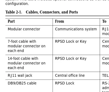
Cables, Connectors, and Ports
Table 2-1 shows the cables, connectors, and ports required to install the RPSD system. This table includes optional connections as well as the basic
configuration.
Installing the RPSD Lock
Install the RPSD Lock between the central office line that is reserved as the remote maintenance and administration channel and the communications system modem (see Figure 2-1). The central office line is usually in a punch-block configuration but may be set up in a number of different ways, including an RJ11 adapter or a multiple-pair gang plug. If one is not already present, install an RJ11 port on the central office line to facilitate installation of the RPSD Lock and also to make subsequent service easier. Label all connections.
Table 2-1. Cables, Connectors, and Ports
Part From To
Modular connector Communications system RJ11 at external modem
7-foot cable with modular connector on each end
RPSD Lock or Key Central office line or modem
14-foot cable with modular connector on each end
RPSD Lock or Key Central office line or modem
RJ11 wall jack Central office line TELCO jack on Lock
DB9/DB25 cable RPSD Lock RS-232 cable to administration terminal or printer or A/B switch
EIA-RS-232 cable DB9/DB25 cable at RPSD Lock
User’s Guide 555-024-402 October 1996 Installation
Page 2-6 Installation
2
The modem location depends on the type of communications system. The modem is located:
■ on the circuit pack for System 75 and DEFINITY Generic 1.
■ external to the communications system for System 85 and DEFINITY
Generic 2.
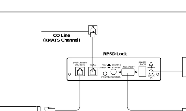
Figure 2-1. Common RPSD Lock Configuration
Connect the RPSD Lock to the administration terminal via the AUX. PORT on the back of the Lock, and power it from an AC outlet or Uninterruptible Power Supply (UPS).
On System 85 and DEFINITY Generic 2, the modems are external to the communications system. Check that the modems are plugged into the UPS, since a power outage that results in either the RPSD Lock or the modem being inaccessible also results in the RMATS channel being inaccessible.
SUBSCRIBER (MODEM) TELCO
AUX. PORT +
!
12VDC 1A ALARM LEADS
POWER MONITOR RED GREEN BYPASS
SECURE
Communications System
CO Line (RMATS Channel)
RPSD Lock
115-Volt AC Outlet
RPSD Administration Terminal Internal or
User’s Guide 555-024-402 October 1996 Installation
Page 2-7 Installation
2
You need the following components to install the RPSD Lock:
■ RPSD Lock
■ The central office line assigned as the RMATS channel (on customer
premises)
■ The communications system modem (on customer premises)
■ 7-foot line cord with RJ11 modular connectors
■ 14-foot line cord with RJ11 modular connectors
■ DB9 (male) to DB25 (female) cable
■ RS-232 cable
■ Administration terminal for the Lock
■ RPSD Lock power supply
■ AC outlet or outlet on the UPS
NOTE: NOTE:
The 7-foot and 14-foot telephone line cords are provided with the RPSD Lock. If additional length cords are needed, the customer must supply them.
Connecting the RPSD Lock to the Central Office
Line
You need the following components to connect the RPSD Lock to the central office line (see Figure 2-2):
■ RPSD Lock
■ Central office line assigned as the RMATS channel
User’s Guide 555-024-402 October 1996 Installation
Page 2-8 Installation
2
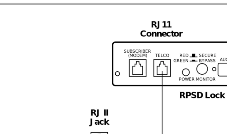
Figure 2-2. RPSD Lock to Central Office Line (RMATS Channel)
To connect the RPSD Lock to the central office line, follow these steps:
1. The customer must contact the Technical Support Center to get the port number for the RMATS channel.
2. Locate the central office line for the RMATS port and install an RJ11 receptacle on the central office line.
3. Connect one end of the 14-foot telephone line cord with RJ11 connectors to the central office line.
4. Plug the RJ11 connector on the other end of the telephone line cord into the TELCO port on the back of the RPSD Lock.
SUBSCRIBER
(MODEM) TELCO
AUX. PORT +
!
12VDC 1A ALARM LEADS
POWER MONITOR RED
GREEN BYPASS
SECURE
RPSD Lock
RJ11
Connector
RJ II
Jack
Tip and Ring Wires
CO Line
(RMATS Channel)
User’s Guide 555-024-402 October 1996 Installation
Page 2-9 Installation
2
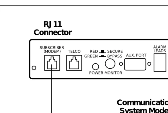
Connecting the RPSD Lock to the
Communications System Modem
You connect the communications system modem to the RPSD Lock by using the 7-foot line cord supplied with the Lock. Obtain further information for the modem from the documentation accompanying that modem.
The following components are needed to connect the RPSD Lock to the communications system modem:
■ RPSD Lock
■ Communications system modem assigned to the RMATS channel
■ 7-foot line cord with RJ11 connectors
To connect the RPSD Lock to the communications system modem, follow these steps (see Figure 2-3):
1. Using the 7-foot line cord with RJ11 connectors on both ends, insert one connector into the SUBSCRIBER port on the back of the RPSD Lock.
User’s Guide 555-024-402 October 1996 Installation
Page 2-10 Installation
2
Figure 2-3. RPSD Lock to Modem
SUBSCRIBER (MODEM) TELCO
AUX. PORT +
!
12VDC 1A ALARM LEADS
POWER MONITOR RED
GREEN BYPASS SECURE
Communications
System Modem
RJ11
Connector
RJ11
User’s Guide 555-024-402 October 1996 Installation
Page 2-11 Installation
2
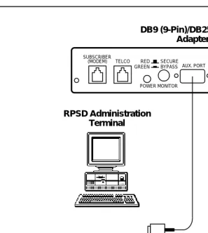
Connecting the RPSD Lock to the Administration
Terminal or Printer
You connect the RPSD Lock to the terminal or printer via the Lock’s AUX. PORT on the back of the Lock and the RS-232 port on the terminal or printer. See Table 2-2 for the pinouts for the AUX. PORT connection. You need the following hardware components to connect the RPSD Lock to the administration terminal or printer:
■ RPSD Lock
■ Administration terminal or printer (printer is optional but recommended)
■ DB9/DB25 cable
■ RS-232 cable with a DB25 connector on one end and the appropriate
connector for the serial printer or administration terminal on the other end
NOTE: NOTE:
Install an A/B switch if you are going to connect both a terminal and a printer. This enables the administrator to change equipment without the trouble of disconnecting and reconnecting the plugs. Follow the directions for connecting a terminal to the AUX. PORT to install the A/B switch.
To connect the RPSD Lock to the administration terminal or printer, follow these steps (see Figure 2-4):
1. Connect the DB9 end of the DB9/DB25 cable supplied with the Lock to the AUX. PORT on the back of the RPSD Lock.
2. Connect the DB25 connector of the RS-232 cable to the DB9/DB25 cable supplied with the Lock.
3. Connect the other end of the RS-232 cable to the terminal or printer. Be sure this end of the RS-232 cable matches the pin descriptions in Table 2-2.
NOTE: NOTE:
User’s Guide 555-024-402 October 1996 Installation
Page 2-12 Installation
2
.
Figure 2-4. RPSD Lock to Administration Terminal or Printer
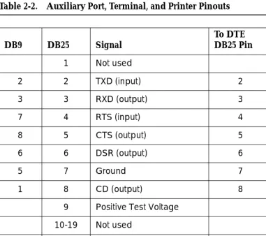
Table 2-2 describes the pinout for the Auxiliary Port connection. Obtain further information for the terminal or printer from the documentation accompanying them. Figure 2-5 and Figure 2-6 illustrate the pin cable connections from the DB25 end of the Lock or Key cable to data terminal equipment (DTE) and data communications equipment (DCE).
SUBSCRIBER (MODEM) TELCO
AUX. PORT + !
12VDC 1A ALARM LEADS
POWER MONITOR RED GREEN BYPASS
SECURE
DB9 (9-Pin)/DB25 (25-Pin) Adapter
RPSD Administration Terminal
User’s Guide 555-024-402 October 1996 Installation
Page 2-13 Installation
2
Table 2-2. Auxiliary Port, Terminal, and Printer Pinouts
DB9 DB25 Signal
To DTE DB25 Pin
To DCE DB25 Pin
1 Not used
2 2 TXD (input) 2 3
3 3 RXD (output) 3 2
7 4 RTS (input) 4 6
8 5 CTS (output) 5 5
6 6 DSR (output) 6 4
5 7 Ground 7 7
1 8 CD (output) 8 20
9 Positive Test Voltage
10-19 Not used
4 20 DTR (input) 20 8
21 Not used
9 22 RI (output) 22 22
User’s Guide 555-024-402 October 1996 Installation
Page 2-14 Installation
2
Figure 2-5. Connections from the DB25 End of the Cable to DTE
Figure 2-6. Connections from DB25 End of Cable to DCE
RPSD (DCE) 2 3 4 5 6 7 8 2 0 2 2 2 3 4 5 6 7 8 2 0 2 2 Transmit Data Receive Data
Request to Send
Clear to Send
Data Set Ready
Signal Ground
Data Carrier Detect
Data Terminal Ready
Ring Indicator
User’s Guide 555-024-402 October 1996 Installation
Page 2-15 Installation
2
Powering Up the RPSD Lock
To power the RPSD Lock, you need:
■ The RPSD Lock power supply
■ An AC wall outlet or an available AC outlet on the UPS. (With a System 85
or DEFINITY Generic 2 communications system, the modem is external to the communications system and should also be powered from the UPS.)
Plug the adapter end of the power supply into the 12VDC port on the back of the RPSD Lock and the other end into an AC wall outlet or an available outlet on the UPS (see Figure 2-10). The red Power LED on the front panel of the Lock goes on and remains on, while the other LEDs on the front panel of the Lock should blink three times and then settle into a Locked condition.
If there is any failure of the LEDs (for example, they do not blink three times or the Power light does not come on), the Lock is defective and must be replaced. See Chapter 5 for troubleshooting. A full explanation of the LEDs for both the RPSD Lock and Key is in Appendix B, “Front Panel LEDs.”
Figure 2-7. RPSD Lock Power Supply
SUBSCRIBER (MODEM) TELCO
AUX. PORT +
!
12VDC 1A ALARM LEADS
POWER MONITOR RED
GREEN BYPASS SECURE
User’s Guide 555-024-402 October 1996 Installation
Page 2-16 Installation
2
Installing the RPSD Key
The RPSD Key is installed between the caller’s modem and the central office line. To install an RPSD Key, you need:
■ RPSD Key
■ Terminal
■ Modem
■ 7-foot line cord with RJ11 modular connectors
■ 14-foot line cord with RJ11 modular connectors
■ One DB9 (male) to DB25 (female) cable
■ RS-232 cable with DB25 connector on one end and the appropriate
connector for the terminal on the other end
■ RPSD Key power supply
■ AC outlet
NOTES:
■ The 7-foot and 14-foot telephone line cords are provided with the
RPSD Key. If additional length cords are needed, the customer must supply them.
■ The RPSD Power Monitor function may be used to provide Alarm
Lead connections for alarming RPSD Key failures. Refer to “External Alarm” earlier in this chapter.
Connecting the RPSD Key to the Terminal
The RPSD Key is connected to the terminal via the AUX. PORT on the back of the Key and the terminal’s RS-232 port. See Table 2-2 for the pinouts for the AUX. PORT connection. The AUX. PORT for the Key is connected in the same manner as the AUX. PORT for the Lock.
You need the following components to connect the RPSD Key to a terminal:
■ RPSD Key
■ DB9/DB25 cable
■ RS-232 cable with a DB25 connector on one end and the appropriate
connector for the terminal on the other end
Follow these steps to connect the Key to a terminal:
1. Connect the DB9 end of the DB9/DB25 cable supplied with the Key to the Auxiliary Port on the Key.
2. Connect the DB25 connector of the RS-232 cable to the DB9/DB25 cable.
User’s Guide 555-024-402 October 1996 Installation
Page 2-17 Installation
2
Connecting the RPSD Key to the Telephone Line
You need the following components to connect the RPSD Key to the telephone line:
■ RPSD Key
■ Telephone line jack
■ 14-foot line cord with RJ11 modular connectors
To connect the RPSD Key to the telephone line, follow these steps:
1. Connect one end of the 14-foot telephone line cord with RJ11 connectors to