Copyright © 1991 AT&T All Rights Reserved Printed in U.S.A
Notice
While reasonable efforts were made to ensure that the information in this document was complete and accurate at the time of printing, AT&T can assume no responsibility for any errors. Changes and corrections to the
information contained in this document may be incorporated into future reissues.
Your Responsibility for Your System’s Security You are responsible for the security of your system. AT&T does not warrant that this product is immune from or will prevent unauthorized use of common-carrier telecornmunication services or facilities accessed through or connected to it. AT&T will not be responsible for any charges that result from such unauthorized use. Product administration to prevent unauthorized use is your responsibility and your system administrator should read all documents provided with this product to fully
understand the features available that may reduce your risk of incurring charges.
Federal Communications Commission (FCC) Statement
This equipment generates, uses, and can radiate radio-frequency energy and, if not installed and used in accordance with the instruction manual, may cause interference to radio communications. It has been tested and found to comply with the limits for a Class A
computing device pursuant to Subpart J of Part 15 of FCC Rules, which are designed to provide reasonable
protection against such interference when operated in a commercial environment.
Operation of this equipment in a residential area is Iikely to cause interference, in which case the user at his/her own expense will be required to take whatever measures may be required to correct the interference.
Trademarks
DEFINITY is a registered trademark of AT&T. In this document, DEFINITY Communications System Generic 3 is often abbreviated to DEFINITY Generic 3 or Generic 3.
DEFINITY Communications System Generic 1 is often abbreviated to DEFINITY Generic 1 or Generic 1.
Acknowledgment
System Management ... 1-1 Initialization ... 1-2 Ongoing Administration ... 1-2 Record Keeping ... 1-2 When to Use This Manual ... 1-3 Organization ... 1-3 Conventions Used in This Document ...1-4
CHAPTER 2. DEFINITY ADMINISTRATION TERMINALS
... Overview ... 715 MT Terminal ...... 2-1 ... 2-1 ... 2-3 513 BCT Keyboard ... 2-4 How to Program the Function Keys for a 513 BCT ... 2-11 4425, 4410, 610, and 615 MT Terminals ... 2-15 AT&T PC 6300 Keyboard ... 2-15
CHAPTER 3. SYSTEM ADMINISTRATION ...
3-1 Administration Sequence ... 3-1How to How to How to How to
Administer Dial Plan and Feature Access Codes ... 4-8 Set Date and Time ... 4-10 Print on Demand ... 4-13 List History ... 4-13
CHAPTER 5. ADMINISTRATIVE TASKS—VOICE TERMINAL
... 5-1 How to Administer Voice Terminals ... 5-1 How to Administer Voice Terminals Without Hardware ... 5-8 How to Administer Data Modules and Voice Terminal Adjuncts ... 5-9CHAPTER 6. HARDWARE RECONFIGURATION
... 6-1 Overview ... 6-1 Circuit Pack Administration ... 6-2CHAPTER 7. SYSTEM BACKUP FOR DEFINITY G1 AND G3i
... 7-1 Save Translation ...7-1 Save and Restore Recorded Announcements ... 7-1 Tape Backup for a System Without the Duplication Option ... 7-2 Tape Backup for a System With the Duplication Option ... 7-4 Tape Errors ... 7-6Figures
Figure 2-1. Figure 2-2. Figure 2-3. Figure 2-4. Figure 2-5. Figure 2-6. Figure 2-7. Figure 2-8. Figure 2-9. Figure 4-1. Figure 4-2. Figure 4-3. Figure 5-1. Figure 5-2. Figure 7-1. Figure 7-2. Figure 7-3. Figure 7-4. Figure 8-1. Figure 8-2. Figure 8-3.
715 MT Keyboard ... 2-3 513 BCT Keyboard Function Keys and Programmable Keys . . . 2-10 Screen Labels Displayed When the LCL MENU Key is Pressed on a 513 BCT .... 2-12 Screen Display When the USER PF SET-UP Key is Pressed on a 513 BCT ... 2-13 Assigning Administrative Functions to
Programmable Function Keys (F1, F2, and F3) on a 513 BCT ... 2-14 4425 Keyboard Assignments ... 2-16 4410 Keyboard Assignments ... 2-17 610 MT Terminal Keyboard Assignments ... 2-18 615 MT Keyboard Assignments Used Without a 513 Emulation Cartridge ... 2-19 Password Change Screen Form ... 4-4 Date and Time Screen Form ... 4-10 Typical History Form ... 4-14 Duplication Station Form Without a Data Module ... 5-6 Duplication Station Form With a Data Module ... 5-6 Save Translation—SPEA ... 7-2 Save Announcements Screen—SPEA ... 7-3 Save Translation—SPE_B ... 7-4 Save Announcements—SPE_B ... 7-5 Save Translation Completion Status ... 8-11 Backup Completion Station ... 8-14 Restore Completion Status ... 8-16
Tables
CHAPTER 1. INTRODUCTION
Overview
This manual provides the information necessary for the System Manager to administer the DEFINITY® Communications System Generic 1 and Generic 3 using any of the administration terminals listed in Chapter 2. If system administration will be performed using the DEFINITY® Communications System Generic 3 Management Applications (G3-MA), refer to DEFINITY®
Communications System Generic 3 Management Applications—Operations, 585-229-202, for
system management procedures. Unless otherwise noted, the DEFINITY Communications Sys-tem will be referred to as the “sysSys-tem” throughout this document.
During the planning process, system requirements were identified by the Account Team and your company. Those requirements were converted into orderable system hardware when the Account Team configured the system. Those features were assigned on a system and per-terminal basis using the forms in the appropriate DEFINITY® Communications System Implementation manual for your DEFINITY System.
The forms in your Implementation manual provide an accurate representation of the screens that are displayed on the system administration terminal. The forms are a blueprint showing how the system and voice terminal features should be constructed.
In order to administer the system, the following must first be done:
● Attend the System Customer Training Course.
● Be familiar with the information in the DEFINITY® Communications System Generic 1
and Generic System 3—Description, 555-230-200, and the DEFINITY Communications System Genetic 1 and Generic 3—Feature Description, 555-230-201.
● Obtain a list from the Account Team and determine what hardware has been ordered. ● Using your Implementation manual, complete:
– the Communications Survey
– the applicable system records and forms
● Retain all the completed system forms in the Implementation manual for use in initializing
and administering the system.
System Management
CHAPTER 1. lNTRODUCTION
System Manager's Role
The System Manager is responsible for the following:
● Adding, changing, removing, and monitoring the system and voice terminal features on a
day-to-day basis
● Performing system backup procedures ● Monitoring system performance -● Maintaining system security
Initialization
After the system is installed and initialized, the System Manager can administer the system using the system administration terminal.
Once completed and duplicated, all forms from the Implementation manual should be sorted into groups. For example, all voice terminal, hunt group, and trunk group forms should be in separate groups. A copy of the Port Assignment Record should be available to keep track of the items being installed in the system. These records can be used as a permanent record to show how the system was initially set up. These records can be replaced as system and voice terminal features are added or removed.
Ongoing Administration
Ongoing administration is the process of using system commands to perform a variety of func-tions to meet business requirements. These funcfunc-tions include: add, change, display, set time, list, duplicate, perform system measurements, perform security and alarms, configure, monitor system performance, and remove system and/or voice terminal features.
Record Keeping
Record keeping plays a vital role in system administration. Records provide a current status of what hardware and which features have been installed.
The Port Assignment Record provides a record of how a system is initialized and administered. Ports are the physical location on a circuit pack where terminals, trunks, or system adjuncts are connected. Once port numbers are assigned, they become the “address” of the associated equipment or facility in the system. It is necessary that a record be made and kept of port assignments for system installation/initialization and ongoing administration.
When to Use This Manual
This manual, along with the Implementation manual, provides the necessary guidelines to admin-ister the system. The Implementation manual, when completed, contains the filled-out forms that reflect how your company wants to implement the system and voice terminal features. The infor-mation on these forms will be electronically entered in the system.
The Implementation manual provides all the details for gathering translation data. It also provides detailed questions and procedures required to complete all the screen forms used to enter trans-lation data into the system.
The System Description and Feature Description manuals should be used to answer any ques-tions concerning system hardware and feature descripques-tions.
You should have thorough training on the following items before attempting to administer the system:
● System and voice terminal features ● Hardware requirements
● Port assignments
● Manager I terminal operation
Organization
This document consists of the following chapters:
● ●
● ● ● ●
●
●
Chapter 1. Introduction describes this document.
Chapter 2. DEFINITY Administration Terminals describes the types of terminals which
can be used to administer DEFINITY Communications Systems and provides details on keyboard layouts and keyboard mapping.
Chapter 3. System Administration provides the order in which features are to be
administered.
Chapter 4. Administrative Tasks-System gives details on performing a variety of
system administration tasks.
Chapter 5. Administrative Tasks-Voice Terminal gives details on performing a
variety of voice terminal administration tasks.
Chapter 6. Hardware Reconfiguration provides a list of commands to determine if the
correct circuit packs are installed so that new voice terminals, trunks, and data modules can be added to the system.
Chapter 7. System Backup for DEFINITY G1 and G3i describes the tasks involved in
backing up the DEFINITY G1 and G3i systems, including saving translations, saving and restoring recorded announcements, tape backup, and tape errors.
Chapter 8. System Backup for DEFINITY G3r describes the tasks involved in backing
CHAPTER 1. INTRODUCTION
● Chapter 9. References provides a list of references for related documents.
● Chapter 10. Abbreviations and Acronyms lists abbreviations and acronyms for terms
used in the DEFINlTY Communications System documentation.
● Glossary defines terms used in the DEFINITY Communications System documentation.
● Index
Conventions Used in This Document
This manual uses the following conventions:
● The names of the comrnands are shown in the following typeface:
change system-parameters feature
● Information you type is shown in the following typeface: EIA.
● Information displayed on the screen is shown in the following typeface: login: ● Keyboard keys are shown as follows: [RETURN]
CHAPTER 2. DEFINITY ADMINISTRATION TERMINALS
Overview
The terminal used to administer a DEFINITY Communications System is identified in this docu-ment as the system administration terminal or the terminal.
The terminal supplied with the system must be located within 50 feet of the system cabinet. The terminal consists of a video display and a keyboard that allow a System Manager to communi-cate with the system. After initialization, the terminal is used to reconfigure translations and to monitor system performance. The terminal can also be used by maintenance personnel.
The system can be equipped with any of the following terminals:
●
●
●
●
●
●
●
If your
715 Multi-Task (MT) Terminal 513 BCT
610 BCT
615 MT Terminal 4410 Terminal 4425 Terminal
AT&T Personal Computer (PC) 6300 using an software package
DEFINITY System is being used with a G3-MA,
AT&T 513, 4410, or 4425 emulation refer to DEFINITY®
Communications System Generic 3 Management Applications—Operations, 565-229-202, for terminal operating
instructions and system management procedures. No operating instructions are given in this document.
The operating instructions in this document cover the 715, 513, 4410, and 4425 terminal types. The operating instructions for the 610 BCT or 615 MT terminal are the same as for the 513 BCT if the 610 or 615 MT terminal is supplied with the 513 emulation cartridge or as for the 4410 if the 513 emulation cartridge is not supplied with the 610 BCT or 615 MT terminal. The instructions describe how the terminal keys can be used, for example, to enter, cancel, display, and change system translations. Instructions on how to use the function keys are also provided.
CHAPTER 2. DEFINITY ADMINISTRATION TERMINALS
Refer to the following manuals for additional operation information on the 715, 513, 610, 4410, or 4425 terminals:
● AT&T 715 MT Terminal User's Guide and Service Manual, 999-300-760, for the 715
ter-minal
● AT&T Information Systems 513 Business Communications Terminal (BCT) Users Guide,
999-700-486IS, for the 513 BCT
● AT&T Information Systems 610 Business Communications Terminal (BCT) Users Guide,
999-300-270IS, for the 610 BCT
● AT&T Information Systems 615 Multi-Tasking Terminal Users Guide, 999-300-302IS, for
the 615 MT terminal
● AT&T Information Systems Display Terminal Users Guide, 999-300-180IS, for the 4410
terminal
715 MT Terminal
The 715 MT terminal emulates the AT&T 615 MT Terminal/System 75 Cartridge combination (513 emulation) when operated in the “BCS” operating mode. The terminal operating mode is set by selecting the Emulation option of the User Preferences submenu or via an escape sequence.
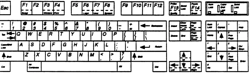
Keyboard Overview
The 715 keyboard is equipped with special keys that allow the user to make corrections and do editing functions. Various function keys perform specific functions. Figure 2-1 shows a layout of the 715 keyboard.
See Table 2-A for a list of the cursor keys, function keys, and programmable keys and a brief description.
The keyboard’s top row includes 14 function keys that provide access to the modules and features of the terminal. They are used as terminal function keys, as screen-labeled keys, or as function keys. For more information on using or programming the 715’s function keys, see the
AT&T 715 MT Terminal Users Guide and Service Manual, 999-300-760.
CHAPTER 2. DEFINITY ADMINISTRATION TERMINALS
513 BCT Keyboard
The 513 BCT keyboard is equipped with special cursor keys that allow the user to make correc-tions and perform editing funccorrec-tions. Function keys that allow single keystrokes to do specific functions are also provided. Each type of key used on the 513 BCT is described in the following paragraphs.
See Table 2-A for a list of the cursor keys, function keys, and programmable keys and a brief description.
Cursor Keys
The cursor keys allow the user to move the cursor between fields and pages on a screen form. The cursor must be positioned on a field before the user can change information in that field. The backspace key is used to correct typing mistakes by backspacing and overstriking mistyped characters.
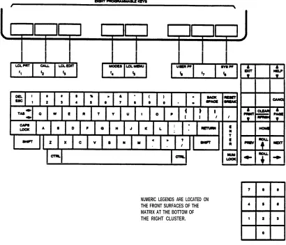
Programmable Keys
The 513 BCT keyboard is equipped with eight programmable keys ( [F1] to [F8] ) located at the top of the keyboard. Each key can be programmed by the user to perform a specific function. The keys are programmed by accessing the USER PF KEY SET-UP screen form. Figure 2-2
shows the layout of the 513 BCT keyboard.
Table 2-A contains a list of the cursor keys, function keys, and programmable keys and a brief description.
Function Keys
Three function keys ([CANCL], [ENTER], and [RETURN]) are provided.
The [CANCL] key is used to erase a form or command. Once the key is pressed, the system returns the user to the enter command: (tasks request) level and asks for a new command. Any data entered on a screen form prior to pressing [CANCEL] is ignored. Any command entered is ignored and the user is returned to the enter command:prompt.
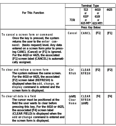
TABLE 2-A. Terminal Keys
[F1] [F1]
[F2] For This Function
To cancel a screen form or command
Once the key is pressed, the system returns the user to the enter com-mand: (tasks request) level. Any data entered on a screen form prior to press-ing CANCL (Cancel) or [F1] is ignored. For the 4410 or 4425, the associated [F1] screen label (CANCEL) is automati-cally assigned.
To clear and redraw a screen form
The system redraws the same screen. For the 4410 or 4425, the associated [F2] screen label (REFRESH) is displayed when the add, change, or
display command is entered and the
screen form is displayed.
715‡
Cancel
Clr/ Rfrsh
To clear all data in a field
The cursor must be positioned at the field the user wants to clear before pressing this key. For the 4410 or 4425, the associated [F4] screen label
(CLEAR FIELD) is displayed when the
add or change command is entered and
the screen form is displayed.
(shift)
Clear Home
Terminal Type
513 4410 4425 or or
610* 610† or or 615 MT* 615 MT† Press Key Below:
CANCL CLEAR RFRSH CLEAR RFRSH (shift) [F2] [F4]
* If a 513 emulation cartridge is used for a 610 or 615 MT, the 610 or 615 MT Terminal keys will function the same as the 513 BCT keys.
[F4]
† If a 513 emulation cartridge is not used with a 610 or 615 MT, the 610 or 615 MT Terminal keys will function the same as the 4410 keys.
CHAPTER 2. DEFINITY ADMINISTRATION TERMINALS
TABLE 2-A (continued). Terminal Keys
Terminal Type
513 4410 4425 For This Function or or
610* 610† 715‡
615 MT* 615 MT† Press Key Below:
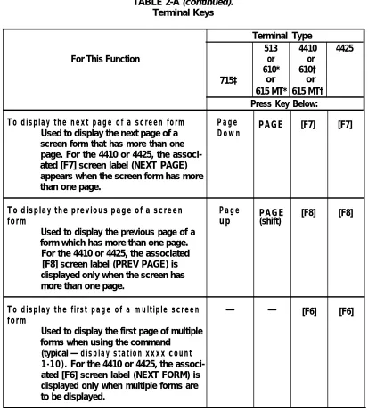
To display the next page of a screen form Page PAGE [F7] [F7]
Used to display the next page of a Down
screen form that has more than one page. For the 4410 or 4425, the associ-ated [F7] screen label (NEXT PAGE) appears when the screen form has more than one page.
To display the previous page of a screen Page PAGE [F8] [F8]
form up (shift)
Used to display the previous page of a form which has more than one page.
For the 4410 or 4425, the associated [F8] screen label (PREV PAGE) is displayed only when the screen has more than one page.
To display the first page of a multiple screen — — [F6] [F6]
form
Used to display the first page of multiple forms when using the command
(typical — display station xxxx count
1-10). For the 4410 or 4425, the
associ-ated [F6] screen label (NEXT FORM) is displayed only when multiple forms are to be displayed.
or or
* If a 513 emulation cartridge is used for a 610 or 615 MT, the 610 or 615 MT Terminal keys will function the same as the 513 BCT keys.
† If a 513 emulation cartridge is not used with a 610 or 615 MT, the610 or 615 MT Terminal keys will function the same as the 4410 keys.
TABLE 2-A (continued) Terminal Keys
Terminal Type
513 4410 4425
For This Function or or
610* 610† 715‡
615 MT* 615 MT† Press Key Below:
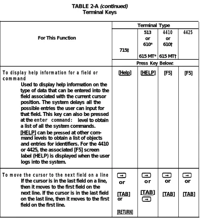
To display help information for a field or [Help] [HELP] [F5] [F5]
command
Used to display help information on the type of data that can be entered into the field associated with the current cursor position. The system delays all the possible entries the user can input for that field. This key can also be pressed at the enter command: level to obtain a list of all the system commands. [HELP] can be pressed at other com-mand levels to obtain a list of objects and entries for identifiers. For the 4410 or 4425, the associated [F5] screen label (HELP) is displayed when the user logs into the system.
To move the cursor to the next field on a Iine
If the cursor is in the last field on a line, or o r or or then it moves to the first field on the
next line. If the cursor is in the last field [TAB] [TAB] [TAB] [TAB] on the last line, then it moves to the first or
field on the first line.
[RETURN]
* If a 513 emulation cartridge is used for a 610 or 615 MT, the 610 or 615 MT Terminal keys will function the same as the 513 BCT keys.
† If a 513 emulation cartridge is not used with a 610 or 615 MT, the 610 or 615 MT Terminal keys will function the same as the 4410 keys.
CHAPTER 2. DEFINITY ADMINISTRATION TERMINALS
TABLE 2-A (continued). Terminal Keys
For This Function
To move the cursor to the previous field on a line
If the cursor is in the first field on a line, then it moves to the last field of the pre-vious line. If it is in the first field of the first line, then it moves to the last field of the last line.
Press Key Below:
o r [TAB] (shift) or [TAB] (shift)
To mOVe the cursor to the next Iine
If the cursor is on the last line, it moves to the first line.
To move the cursor to the previous line
If the cursor is on the first line, it moves to the last line.
To store the data entered on a screen form
Used to enter into system memory the data that is displayed on a screen form. For the 4410 or 4425, the associated [F3] screen label (ENTER) is displayed when the add or change command is entered and the associated screen form is displayed. 715‡ or [TAB] (shift) Terminal Type
513 4410 4425 or
610* 610† or or 615 MT* 615 MT†
ROLL
ROLL
[0]
[2]
[F3]
* If a 513 emulation cartridge is used for a 610 or 615 MT, the 610 or 615 MT
or [TAB]
(shift)
[F3]
Terminal keys will function the same as the 513 BCT keys.
† lf a 513 emulation cartridge is not used with a 610 or 615 MT, the 610 or 615 MT Terminal keys will function the same as the 4410 keys.
TABLE 2-A (continued). Terminal Keys
* † ‡
Terminal Type
513 4410 4425 For This Function or
610* 610†
715‡ or
615 MT* 615 MT† Press Key Below:
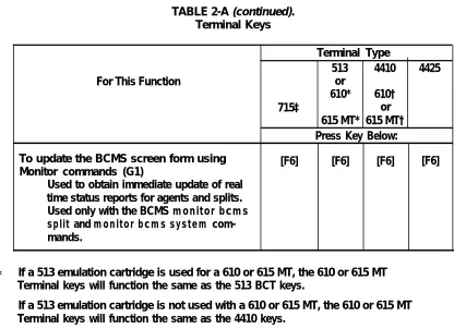
To update the BCMS screen form using [F6] [F6] [F6] [F6] Monitor commands (G1)
Used to obtain immediate update of real time status reports for agents and splits. Used only with the BCMS monitor bcms
split and monitor bcms system
com-mands.
If a 513 emulation cartridge is used for a 610 or 615 MT, the 610 or 615 MT Terminal keys will function the same as the 513 BCT keys.
If a 513 emulation cartridge is not used with a 610 or 615 MT, the 610 or 615 MT Terminal keys will function the same as the 4410 keys.
CHAPTER 2. DEFINITY ADMINISTRATION TERMINALS
NUMERIC LEGENDS ARE LOCATED ON THE FRONT SURFACES OF THE MATRIX AT THE BOTTOM OF THE RIGHT CLUSTER.
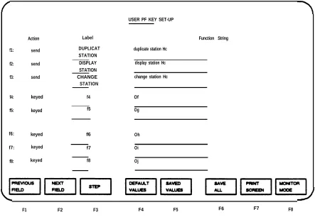
How to Program the Function Keys for a 513 BCT
This section covers the procedures used to program the function keys for a 513 BCT. The pro-grammable function keys can be used to save time by eliminating unnecessary typing. For exam-ple, a function key can be programmed to type the change station command. When the pro-grammed key is pressed, change station appears on the terminal screen. The user then enters the extension number associated with the voice terminal. The user should be familiar with the User PF Keys section in the 513 BCT User's Guide, 999-700-486IS, before attempting to pro-gram the function keys. Propro-gram the function keys as follows:
1. 2. 3. 4. 5. 6. 7. 8. 9. 10. 11. 12. 13. 14. 15. 16.
Turn on the 513 BCT. Log into the system.
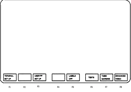
Press [SHIFT] and [F5] (LCL MENU). See Figure 2-3.
The function for each programmable key is displayed at the bottom of the screen. See Figure 2-3.
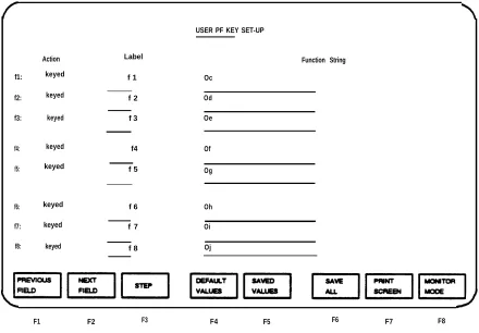
Press [F3] (USER PF SET UP). See Figure 2-4.
Screen displays the USER PF KEY SET-UP screen form. See Figure 2-4. The values displayed are default values which can be changed.
Press [F8] (MONITOR MODE). This allows the user to program control characters asso-ciated with the USER PF KEY SET-UP screen form. See Figure 2-4 or 2-5.
To program [F1] , position the cursor under the Action heading for [F1] . Type in send.
Position the cursor under the Label heading.
Enter the desired administration command. (This command can be typed on two lines.) For example, if you type in duplicate station, this is the function assigned to [F1] . See Figure 2-5 for examples on how to enter the duplicate station, display station and
change station commands.
Position the cursor under the Function String heading. Type in the desired string, up to 80 characters.
Repeat the above steps for other keys you want to program.
Press the [F6] (SAVE ALL) key. This stores the currently displayed values for all the keys that were programmed. The default values that were not changed remain with the key.
CHAPTER 2. DEFINITY ADMINISTRATION TERMINALS
F1 F2
FIGURE 2-3. Screen
F3 F4 F5
Labels Displayed When the LCL MENU
F6 F7 F8
Function String USER PF KEY SET-UP
Action Label
f1: keyed f 1 Oc
f2: keyed f 2 Od
f3: keyed f 3 Oe
f4: keyed f4 Of
f5: keyed f 5 Og
f6: keyed f 6 Oh
f7: keyed f 7 Oi
f8: keyed f 8 Oj
F1 F2 F3 F4 F5 F6 F7 F8
CHAPTER 2. DEFINITY ADMINISTRATION TERMINALS
USER PF KEY SET-UP
Label Function String
f1:
f2:
f3:
duplicate station Hc
display station Hc
change station Hc
f4: keyed
f5: keyed f5 Og
f6: keyed f6
f7: keyed
f8:
Action
send
send
send
DUPLICAT STATION DISPLAY STATION CHANGE STATION
f4
f7
Of
Oh
Oi
keyed f8 Oj
F1 F2 F3 F4 F5 F6 F7 F8
4425, 4410, 610, and 615 MT Terminals
The 4425, 4410, 615 MT, and 610 terminals can also be used to administer DEFINITY Communi-cation Systems. The 4425, 4410, 615 MT, and 610 terminals have eight function keys ([F1] through [F8]) that are automatically assigned functions by the system software. These keys allow the user to edit and fill out the screen forms and then submit the forms into system transla-tions. Since the keys are assigned by the system, they cannot be programmed by the user. The function assigned to each of the keys is displayed at the bottom of the 4425 or 4410 screen.
Figure 2-6 shows the location of the eight keys and their relationship to the screen for the 4425. Figure 2-7 shows the same information for the 4410. Figure 2-8 shows the information for the 610. Figure 2-9 shows the information for the 615 MT Terminal.
When the user logs into the system and receives the enter command: prompt, the system
automatically assigns the CANCEL function to [F1] and the HELP function to [F5] .
When the user types in a command, the system automatically assigns the REFRESH function to [F2] , the ENTER function to [F3] , and the CLEAR FIELD function to [F4] . These functions will appear at the bottom of the screen after the station screen form is displayed.
If the screen form has more than one page, the system automatically assigns the NEXT PAGE
function to [F7] and the PREV PAGE function to [F8] . See Table 2-A for a description of how to use the keys.
AT&T PC 6300 Keyboard
The PC 6300 function keys will work like a 4410 if the terminal is equipped with an AT&T 4410 emulation software package or a 4425 if it is equipped with an AT&T 4425 emulation software package. The function keys are automatically assigned by system software when the user logs in.
If the PC is equipped with an AT&T 513 emulation software package, the user must assign func-tion keys such as HELP and NEXT PAGE to the funcfunc-tion key labels on the PC screen and then use these keys as function keys. The system does not automatically assign the function keys. The escape sequences that must be assigned to the labels for the function keys are in the table below:
TABLE 2-B. Escape Sequences L a b e l Escape Sequence HELP [ESC] OM
NEXT PAGE [ESC] [U PREV PAGE [ESC] [V
ENTER [ESC] SB
CHAPTER 2. DEFINITY ADMINISTRATION TERMINALS
CHAPTER 2. DEFINITY ADMINISTRATION TERMINALS
CHAPTER 3. SYSTEM ADMINISTRATION
CHAPTER 3. SYSTEM ADMINISTRATION
Administration Sequence
After the system is installed, the System Manager must enter the translation data into the system memory using the system administration terminal.
Before initializing the system, verify that the screen displays Login: If your terminal does not display Login:, call your AT&T Account Team.
The Implementation manual for your DEFINlTY system provides the details for gathering the translation data. It also provides detailed descriptions and procedures required to complete all the screen forms used to enter translation data into the system. The document also provides the administration commands that can be used to administer system and voice terminal features, and error messages.
Obtain all duplicated forms from the Implementation manual and sort them into groups. For example, forms for all voice terminals, and hunt and trunk groups should be separated. A copy of the Port Assignment Record should be available to keep track of the items being installed in the system.
When entering the translation data into the system, the System Manager should periodically save the translations on tape. This creates a nonvolatile copy of the translation already entered into the system. If a power outage or system failure occurs, the translation data saved on the tape will not have to be entered again.
The system features should be entered into the switch in an ordered manner. The following is the recommended order in which data should be entered into the system:
1. 2. 3. 4. 5. 6. 7. 8. 9. 10. 11. 12. 13. 14.
Login and Password (Change Password, if necessary) Dial Plan
Feature Access Codes
System Features (Class of Service and Class of Restriction) Console Parameters Attendant Consoles System Parameters Voice Terminals Modules Netcon Channels
Groups (hunt groups, pickup groups, etc.) Trunk Groups
These items cannot be added to the system; however, they can be changed to suit business needs by entering the change command for that feature and changing the screen form. The add
command must be used to add trunks, pickup groups, hunt groups, and intercom groups. The
duplicate command can be used to duplicate voice terminals and data modules.
Login and Password
Once all the forms have been grouped, the System Manager can log into the system using the terminal and receive the enter command:prompt. The System Manager can change the
pass-word, if so desired.
Establish a Dial Plan
The Dial Plan and Feature Access Codes (FACs) must be administered before voice terminals, hunt groups, pickup groups, coverage groups, and attendant consoles can be administered. The default values for the Dial Plan can be changed if they do not meet business requirements. The Dial Plan can be changed by entering the command change dial plan and then changing the default values on the screen form. The Dial Plan can use up to 5 digits.
Feature Access Codes
The defaulted values on the FAC form can be changed if they do not meet business require-ments. FACs can be changed by entering the command change feature-access-codes and
then changing the default values on the screen form. The number of digits assigned to the FAC must agree with the Dial Plan.
System Features
System features include the Class of Service (COS) and Class of Restriction (COR). These features cannot be added; they can only be changed. To change these system features, enter the command change cos for COS or change cor 0-63 for COR. Once the screen form is displayed, the data entries can be changed.
Console Parameters and Attendant Consoles
CHAPTER 3. SYSTEM ADMINISTRATION
System Parameters
System parameters allow the System Manager to assign values for system related features such as Leave Word Calling (LWC), Hospitality Features, and Station Message Detail Recording (SMDR).
Voice Terminals
Once the Dial Plan and FACs have been assigned, the System Manager can add the various voice terminals. The duplicate command can be used to add the same types of voice terminals. The extension number, location, type, and user name should be entered on the form.
Modules
Data modules can be assigned after voice terminal administration. Some data modules must be added during voice terminal administration if the voice terminal has a data module. Other data modules can be added separately.
Netcon Channels
Netcon Channels are used to provide switched data access for the following:
● Station Message Detail Recording
● On-premises administration/maintenance terminal ● Remote administration/maintenance terminal ● Property Management System (PMS) Link ● Station Message Detail Recording
● PMS Log Printer ● Journal Printer
● Recorded Announcements ● System Printer
● Remote Administration/Maintenance Terminal.
Netcon channels are assigned by entering the command add data-module (extension number
or next) and then entering Netcon in the Type field. Up to four Netcon channels can be
Groups
After the voice terminals are added, the following items can be administered using the add com-mands:
● ● ● ● ● ●
Abbreviated Dialing (System, Group, Enhanced) Hunt Groups
Call Coverage Answer Groups Pickup Groups
Intercom Groups
Terminating Extension Groups
Trunk Groups
Trunk groups are assigned by entering the command add trunk group 1-99 (or next). For the Hospitality Reduction Parameter feature, only 50 trunk groups can be assigned.
The Network Access Features forms are filled out by the Account Team and must always be entered. The Network Access forms are provided in two sections, Private and Public. The Public Network Access includes the Trunk Group forms which, when entered, provide voice terminals and attendants with access to and from the public network.
Private Network Access allows calls to be connected to several networks, such as the following:
● ● ● ● ● ● ●
Common Control Switching Arrangement (CCSA) Digital Signal Level 1 (DS1) Interface
Electronic Tandem Network (ETN)
Enhanced Private Switched Communications Service (EPSCS) Access Tandem Tie Trunk Network (TTN)
CHAPTER 4. ADMINISTRATIVE TASKS-SYSTEM
CHAPTER 4. ADMINISTRATIVE TASKS-SYSTEM
This chapter covers administrative tasks that allow the System Manager to change system features to meet business requirements. The following administrative tasks are covered:
● How to login and log off ● How to change your password
● How to set up the system to allow remote administration ● How to administer the system from a remote location ● How to administer Netcon channels
● How to initially administer Dial Plan and Feature Access Codes (FACs) ● How to set date and time
● How to print on demand ● How to list history
How to Log In and Log Off
The system translations are protected by the Iogin/password procedures. The login name identi-fies the type of terminal user to the system. The password is a personal code that can be changed periodically to enhance system security. Before any system administration commands or functions can be executed, the System Manager must successfully log in to the system and receive the enter command: prompt.
System Login Procedures
Note: If your DEFINlTY system is being used with a G3-MA, refer to DEFINITY®
Com-munications System Generic 3 Management Applications—Operations, 585-229-202, for login procedures.
The following procedure is used for logging into the system. 1. Turn on the terminal, if required. Screen displays:
.
Login:
2. Enter your login name and press [RETURN]. Screen displays:
Password:
3. Enter your password and press [RETURN].
For security reasons, the password is not displayed as you type it. The system verifies that a valid login and password have been entered. If an invalid login or password is entered, the system responds with
INCORRECT LOGIN
Login:
4. If INCORRECT LOGIN is displayed, you must repeat Steps 2 and 3. 5. If the system recognizes the Iogin and password name,
Terminal Type (Enter 513, 4410, or 4425): [513]
is displayed on the screen.
6. Do one of the following to identify the terminal type:
● If the system is equipped with a 715 BCS, press [RETURN]. This will enter [513]
which is the defauLt terminal.
Note: The 715 must be set to the “BCS” emulation mode which causes it to function like a 615 MT Terminal equipped with a 513 emulation cartridge.
● If the system is equipped with a 4410 terminal, enter 4410 and press [RETURN]. ● If the system is equipped with a 4425 terminal, enter 4425 and press [RETURN]. ● If the system is equipped with a 513 BCT, press [RETURN]. ([513] is the system
default.)
● If the system is equipped with a 610 or 615 MT Terminal that has a 513
emula-tion cartridge, press [RETURN]. ([513] is the system default.)
CHAPTER 4. ADMINISTRATIVE TASKS-SYSTEM
7. If enter command:is displayed, you can enter the desired command. Press [HELP] to obtain the list of permissible commands.
System Logoff Procedure
The system logoff procedure should be performed any time the system terminal is not being used. This assures the system translations will not be accidentally corrupted. To log off the sys-tem, type logoff and press [RETURN]. The system automatically disconnects you from the sys-tem.
If the user logs off at a terminal located within 50 feet from the switch, the system will automati-cally request a login. The terminal user accessing the maintenance board, data channel, or Net-con channel will be disNet-connected from the system when logoff is typed in. These users must dial up the system in order to access the system.
How to Change Your Password
Password administration allows the user to change the password used to access the system. This section provides the steps required to change a password.
The password should be changed if another person has discovered it. It should also be changed if someone has gained access to the system and made changes to features that could alter busi-ness transactions.
The System Manager's password must be obtained from the installation organization responsible for installing the system. The login name cannot be administered.
The System Manager's password should also be changed each time a new person takes over the System Manager role. The password can be changed once the user has logged onto the sys-tem.
Do not give out passwords to anyone. Keep passwords in a locked place. Change passwords periodically, at least every six months.
The following procedure is used to change a password. 1. Verify that the screen displays:
enter command:
2. Enter change password xxxxxxx (where xxxxxxx is the Iogin) and press [RETURN].
3. The Verify Password Change form is dislayed on the screen (see Figure 4-1 ). 4. The cursor is positioned on Your Current Password field.
5. Enter the current password you logged in with and press [RETURN]. 6. Cursor is positioned on New Password For Login Name.
Note: Valid passwords contain four to seven alphabetic or numeric characters, or a combination of alpha and numeric characters.
8. Cursor is positioned on New Password (enter again):
9. Re-enter your new password. 10. Press [ENTER].
11. Verify that the screen displays:
command completed successfully
enter command:
change password xxxxxxxx Page 1 of 1
PASSWORD CHANGE
Change Password For Login Name: xxxxxxx Your Current Password:
New Password For Login Name:
FIGURE 4-1. Password Change Screen Form
How to Set Up the System to Allow Remote Administration
Another way to administer the system, other than the system administration terminal, is from a Remote Terminal. The Remote Terminal can be located either on or off the customer's premises.
All functions of the system administration terminal are retained by the Remote Terminal; how-ever, terminal operation speed is limited to 1200 bps (bits per second) from a dial-up facility. Up to five terminals can be connected to the system. In any type of configuration, only one termin-al at a time can be used for administration purposes (such as adding, changing, or deleting sys-tem and voice terminal features). The other terminals may be used by Automatic Call Distribution (ACD) supervisors to view Basic Call Management System (BCMS) information. To set up the system to allow for Remote Administration, use the following steps:
CHAPTER 4. ADMINISTRATIVE TASKS-SYSTEM
Note: Remote Access users should be careful when using any command that requires user
1. 2.
3. 4.
input such as next page. This command, if not used properly, will not let the system time out after 30 minutes and logoff the user. If the command is not used properly, system alarms cannot be reported which may affect system service.
If not translated previously, translate four Netcon channels. (See “How to Administer Netcon Channels” in this chapter.)
Translate a Uniform Call Distribution (UCD) Hunt Group using a Hunt Group form.
a. In the Group Extension field, enter an extension number. If the system is equipped with Direct Inward Dialing (DID), enter a DID extension number.
b. In the Group Members Assignment field, enter the four extension numbers (non-DID numbers) previously assigned to the four Netcon channels.
If the system will be remotely administered from an on-premises terminal, no additional translations are required.
If the system will be remotely administered from an off-premises location via a dial-up facility, complete Steps 3 and 4.
Translate a pooled modem if not translated previously.
Translate a trunk group in one of the following ways described in the table below. DID Equipped Systems
DID Equipped Systems Using a Non-DID Trunk
Non-DID Equipped Systems (calls made from Remote
[off-premises] terminal will be to the Listed Directory Number [LDN]) Non-DID Equipped Systems (calls made from Remote
[off-premises] terminal will be to a
trunk dedicated to Remote Administration)
Using a DID Trunk Group form, translate a new trunk. The NAME (TeI. number) assigned in the Group Member
Assignments field must be the same DID number assigned to the UCD hunt group (see step 2a).
Using a CO Trunk Group form, translate a new trunk group. In both the Incom-ing Destination and Night Ser-Vice fields, enter the UCD hunt group
extension number (see Step 2a). If not translated previously, translate a Trunk Group containing the LDN.
How to Administer the System From a Remote Location
Make sure data terminal speed settings are set at 1200 bps. Top speed for a data or Netcon channel is 1200.
1. Using either the keyboard or a voice terminal, dial the UCD group extension number. This number will be one of the following:
a. From off-premises:
● a DID number (seven or 10 digits) ● an LDN (seven or 10 digits)
● a trunk number dedicated to Remote Administration (seven or 10 digits)
b. From on-premises:
● an extension number
2. If a DID number, dedicated trunk number, or extension was dialed, receive data tone or visually receive answer confirmation.
If an LDN was dialed, the attendant will answer. Ask to be transferred to the UCD group extension number. Receive data tone or visually receive answer confirmation.
3. Screen displays login.
4. Enter your login and password. 5. Perform system administration. 6. Logoff and disconnect.
How to Administer Netcon Channels
This section contains the procedures required to administer system Netcon channels. The sys-tem has four Netcon channels (01 through 04) that are used to provide switched data access. The system administration terminal, which is located within 50 feet of the system cabinet, is not administered using Netcon channels. The system administration terminal should not be confused with the on-premises or remote system administration terminals.
The Netcon channels are administered separately using the Data Module form and entering net-con in the Type field. The Netcon channels are assigned to the Network Control circuit pack. One Netcon Channel form must be completed for each channel.
Once the Netcon channel has been assigned, the user must adminster the modules or modems required to support SMDR, system administration/maintenance terminals, recorded announce-ments, and/or the PMS Iink.
CHAPTER 4. ADMINISTRATIVE TASKS-SYSTEM
All four Netcon channels must be assigned. The following steps can be used to add a data or Netcon channel: 1. 2. 3. 4. 5. 6. 7. 8. 9. 10. 11. 12. 13. 14. 15. 16.
Verify that the terminal displays:
enter command:
Enter add data module 4444 where 4444 is the extension number assigned to the Netcon channel. The extension number will appear in the Data Extension field on the screen form. Press [RETURN]. The screen displays a Processor Data Module (PDM) form. The cursor is positioned on the TYPE field.
In the TYPE field, enter netcon and press [RETURN]. Screen displays the Netcon Channel form.
The cursor is positioned on the Physical Channel field.
Enter a Netcon channel number from 01 through 04 and press [RETURN]. The cursor is positioned on the Name field.
Make no entry and press [RETURN]. Cursor is positioned on the COS field.
Enter a COS number from 0 through 15 and press [RETURN]. The cursor is positioned on the COR field.
Enter a COR number from 0 through 63 that will allow or deny access and press [RETURN].
The cursor is positioned on the Abbreviated Dialing (AD) List 1 field. Make no entry and press [ENTER].
The screen displays:
command successfully completed,
enter command:
Repeat Steps 1 through 16 until all four Netcon channels have been established. A dif-ferent extension number must be entered for each Netcon channel. The system automatically assigns the extension number if next is entered at the end of the add
data-module command (add data-module next).
The Netcon channels can be added by entering the command duplicate data-module xxxx
(extension number to be duplicated). This command must be entered for each Netcon
chan-nel being added.
How to Change a Netcon Channel
Netcon channels can be changed by entering the command change data module 4444 and pressing [RETURN]. Extension number 4444 is the extension number assigned to the data or Net-con channel.
Once the form is displayed on the screen, the user can make changes. Once all changes have been made, press [ENTER] to submit the changes into system translations.
How to List Netcon Channels
The list data-module command can be used to display a list of all Netcon channels that have been assigned in the system. The display gives a list of all data modules and Netcon channels and their associated data, which includes:
● Extension ● Port number
● Type of module (Netcon channels are listed along with the other types of modules) ● Name (if assigned)
● Class of Service (COS) ● Class of Restriction (COR)
● Information Systems Network (ISN) (this field shows if the data module is connected to
the ISN)
The display data-module xxxx (extension number) [print] command can be used to obtain a
printout for one Netcon channel.
How to Administer Dial Plan and Feature Access Codes
The Dial Plan Record and the FACs can be administered together to insure continuity for the number of digits assigned to FAC. The number of digits used to dial the FAC must agree with the number of digits assigned to the FAC field on the Dial Plan Record. The system does not allow a
mismatch between these numbers. For example, if the Dial Plan Record has two digits assigned for FAC, then each FAC must be assigned two digits. The user dials these digits to activate and deactivate a feature.
The Dial Plan Record must be administered before assigning FACs, trunk access codes, and voice terminal extensions. The Dial Plan Record can be administered as a stand-alone screen form as long as the changes being made do not affect the FACs, Trunk Access Codes (TACs), and voice terminal extension numbers. Once the TACs and voice terminal extension numbers have been assigned, the user cannot change the Dial Plan Record.
CHAPTER 4. ADMINISTRATIVE TASKS-SYSTEM
The following steps give an example of how to change a FAC from three to two digits. 1.
2. 3. 4. 5. 6.
7. 8. 9. 10.
11. 12. 13.
Verify that the screen displays:
enter command:
Enter change feature-access-codes and press [RETURN]. The screen displays the FAC form.
Position the cursor over the 3-digit FAC and press the space bar until the 3-digit code disappears.
Press [RETURN] and repeat the above step until all 3-digit FACs have been removed. Press [ENTER]. The screen displays:
command successfully completed,
enter command:
Enter change dialplan and press [RETURN]. Screen displays the Dial Plan Record form.
Press [RETURN] until the cursor is positioned on the 1: Number of Digits field. Enter 2 and press [ENTER]. The screen displays:
command successfully completed,
enter command:
Enter change feature-access-codes and press [RETURN]. The screen displays the FAC form.
Assign 2-digit FACs to the desired features. After all codes have been assigned, press [ENTER]. The screen displays:
command successfully completed,
How to Set Date and Time
The system date and time are set using the Date and Time form (see Figure 4-2). This form is displayed on the terminal screen and is modified using the terminal keyboard. The time must be reset for daylight savings time. The correct time and date assure that SMDR records are correct for the records being kept. SMDR will not work until the date and time have been entered. Use the following procedure to set the system date and time:
1. Log in.
2. Verify that the screen displays:
enter command:
3. Enter set time and press [RETURN].
4. Verify that the screen displays the Date and Time form (see Figure 4-2). Note: The cursor is positioned on the Day of the Week: line.
set time page 1 of 1 DATE AND TIME
DATE
Day of the Week: Month: Day of the Month: _ Year: TIME
Hour: _ Second: XX Minute: _
FIGURE 4-2. Date and Tlme Screen Form 5. Enter the day of the week (Sunday-Saturday) and press [RETURN].
Note: The cursor is positioned on Month:.
6. Enter the current month (January-December) and press [RETURN]. Note: The cursor is positioned on Day of the Month:.
CHAPTER 4. ADMINISTRATIVE TASKS-SYSTEM
8. Enter the current year (1990-2099) and press [RETURN]. Note: The cursor is positioned on Hour:.
9. Enter the current hour (0-23) and press [RETURN]. Table 4-A shows the standard time conversion to 24-hour time. Enter the 24-hour time as shown. For example, if the current time is 2:00 p.m., enter 14.
Note: The cursor is positioned on Minute:.
10. Enter the current minute (0-59).
11. Press [ENTER].
12. Verify that the screen displays:
The set time form is completed successfully enter command:
Enter save translation and press [RETURN] so the correct time and date will be entered in system translations. See Chapter 6 for save translation information.
13. Verify the date and time data by entering Display Time and pressing [RETURN].
Note: The Date and Time form is displayed showing all data entered, followed by:
TABLE 4-A. Conversion to 24-Hour Clock 12-Hour
Standard Time 24-Hour Clock Clock
12:00 a.m. 0
1:00 a.m. 1
2:00 a.m. 2
3:00 a.m. 3
4:00 a.m. 4
5:00 a.m. 5
6:00 a.m. 6
7:00 a.m. 7
8:00 a.m. 8
9:00 a.m. 9
10:00 a.m. 10 11:00 a.m. 11 12:00 p.m. 12
1:00 p.m. 13
2:00 p.m. 14
3:00 p.m. 15
4:00 p.m. 16
5:00 p.m. 17
6:00 p.m. 18
7:00 p.m. 19
8:00 p.m. 20
9:00 p.m. 21
CHAPTER 4. ADMINISTRATIVE TASKS-SYSTEM
How to Print on Demand
The user can get a printout when print or the abbreviated version pr, is entered as the last qual-ifier for the list and display commands. For example, entering display abbreviated-dialing group 20 print provides a printout for AD group number 20.
The terminal must have a printer connected to it before a hard copy printout can be obtained. The following procedure can be used to obtain a printout of Pickup Group 25.
1. 2. 3.
Log on.
Enter display pickup-group 25 print or display pickup-group 25 pr and press [RETURN].
The screen displays the form for Pickup Group 25. At the same time, the screen form is also printed out at the printer.
How to List History
This list history command provides a listing of the latest (250 maximum) completed “data affect-ing” administration and maintenance commands. The following commands are “data affectaffect-ing”:
add recycle busyout release change remove clear reset disable set duplicate test
enable wp (write physical)
Figure 4-3 is an example of a typical list history command as displayed on the terminal. The command results are displayed in last-in first-out order. The date that translations were last saved on tape is printed followed by information under columns as follows:
● Date: Day and month that the command was issued.
● Time: Hour and minute that the command was issued.
● Port: A 3- or 4-character identifier that shows which port or ports the user was connected
to. The identifiers and their associated meaning are:
Identifier Port Connection
Extended Port Network (EPN) Maintenance circuit pack in expansion port network NET Network Control circuit pack
System Administration Terminal Processor circuit pack TSC Processor circuit pack SMDR Processor circuit pack
● Login: The login of the user performing the data command.
● Actn: The first four letters of the action command word.
● Object: The first 12 letters of the object command word.
● Qualifier: The first 36 letters of the qualifier (or qualifiers) command word.
list history page 1
History
Date of Translation Loaded: 19:53 Wed Jul 19, 1990
Date Time Port Login Actn Object Qualifier ---- ---- ---- --- ---- ---
---07/18 12:34 EPN cust2 add station 1120 07/18 12:23 EPN cust2 chan dialplan
07/16 09:44 SAT craft rele station 504 07/16 09:22 SAT craft busy station 504 07/15 15:25 SAT cust chan station 507 07/15 15:18 SAT cust add station 507 07/15 15:09 SAT cust add station 506 07/15 15:06 SAT cust add station 505 07/15 15:04 SAT cust add station 504 07/15 15:02 SAT cust add station 503 07/15 15:01 SAT cust add station 502 07/15 15:00 SAT cust add station 501
CHAPTER 5. ADMINISTRATIVE TASKS-VOICE TERMINAL
CHAPTER 5. ADMINISTRATIVE TASKS—VOICE TERMINAL
How to Administer Voice Terminals
Voice terminal administration is an integrated set of procedures that allow the user to add, change, remove, duplicate, display, and list the translation data associated with voice terminals. The voice terminal must be installed, connected, and initialized in system translations before the user can make a call. Other screen forms may be filled out to assign a voice terminal in a feature operation, such as call pickup, call coverage, etc.
The following are the classes of operations in voice terminal administration:
● Adding a voice terminal refers to entering the translation data needed to originate and/or
terminate calls at a terminal and to provide button access to features and functions.
● Changing a voice terminal refers to updating the translation data associated with an
existing terminal.
● Removing a voice terminal refers to deleting all the translation data of an existing
termi-nal from the system.
● Displaying a voice terminal refers to displaying the screen form for a voice terminal.
● Duplicating a voice terminal refers to adding a voice terminal which has the same
confi-guration as an existing voice terminal.
● Listing allows the user to obtain a list of all, or a selected range of, voice terminals in the
system. The user can also obtain a list of all groups in which the voice terminal is a member.
● List extension type allows the user to identify a specific extension, or examine a range
of extensions. This command is also used to identify what types of groups the extension belongs to and to list extension numbers and their types in a given range to help locate and examine voice terminals.
● Enhanced Terminal Administration allows for the administration of new voice terminals
that are not supported by the system software. For any new voice terminal type, the Enhanced Terminal Administration feature allows new terminals to be “mapped” to an existing or supported type. The mapping is accomplished by using the Alias Station screen form. The alias name of the station can then be used when administering sta-tions of that type.
Before a voice terminal can be removed from the system, it must be removed from the following:
● Code Calling List
● Leave Word Calling (LWC) System Retrievers List
● Hunt Groups Assigned to the Call Management System (CMS)
Translation data change may also be prevented when any affected feature is currently active; for example, a voice terminal cannot be removed while the message waiting indicator is on. The voice terminal must be idle before any features can be added or changed. Certain feature but-tons must be unlocked (not in use) before they can be changed. The port number, message wait-ing indicator, and each button are locked. A voice terminal cannot be removed if one of the locked items is active.
If voice terminal feature buttons are changed on the screen form, the labels for those feature but-tons that appear on the voice terminal must also be changed to agree with the associated screen form.
Note: Removing a voice terminal from a hunt group that has CMS will automatically remove the voice terminal from the hunt group and CMS.
The information in the following paragraph must be used when adding, changing, or removing voice terminals. A voice terminal cannot be assigned to a port number that is already assigned.
Note: If the circuit pack is not installed in the carrier, the System Manager can assign a cir-cuit pack to the system by entering the command change circuit-pack and inputting the circuit pack code beside the available slot number. Once the circuit pack code has been assigned, the System Manager can then enter the appropriate port number on the screen form for the voice terminal.
● 500, 2500, 2500 YMGK, 7101A, 7103A, 7102, 7102A, 7104A, 8102, or 8110 Voice
Ter-minals: For all versions, up to right voice terminals can be assigned to one TN742
Analog Line circuit pack. Up to 16 voice terminals can be assigned to one TN746 or TN746B Analog Line circuit pack. If you are using the 8102 or 8110 voice terminal with a TN746 circuit pack, then auxiliary power is needed. Up to eight voice terminals can be assigned to one TN769 Analog Line circuit pack. Up to 24 voice terminals can be con-nected to a DS1 Interface TN767 circuit pack
● 7403D, 7405D Voice Terminals, 510 BCT, or 513 BCT: Up to eight voice terminals can
be assigned to one TN754 Digital Line circuit pack. Up to 16 Digital Line circuit packs may be placed on one port carrier if only 7403D voice terminals are used. Up to 12 Digi-tal Line circuit packs may be placed on one port carrier if 7405D voice terminals are used. In either case, the carrier may be fully loaded with other type circuit packs.
● 7434D, 7440, 741OD, or 7410 Plus: Up to eight voice terminals can be assigned to one
TN754 Digital Line circuit pack.
● 7401D, 7401D PIus, 7404D, 7406D, 7406BIS, 7406 Plus, 7407D, Enhanced 7407D
(02C), or 7407 Plus Voice Terminals: Up to eight voice terminals can be assigned to
CHAPTER 5. ADMINISTRATIVE TASKS-VOICE TERMINAL
● 7303S, 7305S, or 7309H Voice Terminals: Up to eight voice terminals can be assigned
to one TN762 Hybrid Line circuit pack.
● 7302H01B, 7303H01B, 7305H01B, or 7305H02B Voice Terminals: Up to eight voice
terminals can be assigned to one TN762 Hybrid Line circuit pack.
● ISDN 7505, 7508, or 7507 Voice Terminals: In a multipoint configuration, up to 24 voice
terminals can be assigned to the ISDN-BRI circuit pack TN556. In a point-to-point confi-guration, 12 voice terminals can be assigned.
● ISDN 8503T Voice Terminal: In a multipoint configuration, up to 24 voice terminals can
be assigned to the ISDN-BRI circuit pack TN556. In a point-to-point configuration, 12 voice terminals can be assigned.
● 10, 20, or 30 MET Sets: Up to four voice terminals can be assigned to one TN735 Met
Line circuit pack.
● CALLMASTER® Digital Voice Terminals: Up to eight CALLMASTER digital voice
ter-minals can be connected to a TN754 or TN784 Digital Line circuit pack. A voice terminal cannot have display buttons without having a display module.
Voice Terminal Commands
The following information explains how voice terminal commands are used to administer voice terminals.
Add a Voice Terminal
Two processes are used to add a voice terminal: 1) physically installing the voice terminal and 2) adding voice terminal translations to memory. Adding translations to memory tells the system the characteristics you want associated with the voice terminal and allows processing calls to and from the voice terminal.
Note: Digital-type voice terminals should be assigned in the system before analog-type ter-minals.
● To add a voice terminal to the system, enter add station 3222. In this example, add
is the action command, station is the object, and 3222 is the qualifier (value). By adding a qualifier (3222), the system automatically assigns 3222 as an extension number in the
Extension # field on the form. Once the Voice Terminal form appears on the screen, you can enter the desired data for that voice terminal.
The 7302H01B and the 7303H01B are assigned using the 7303S Voice Terminal form. The 7305H01B and 7305H02B are assigned using the 7305S Voice Terminal form.
Change Information on a Voice Terminal
The change command allows you to change translations on an existing voice terminal.
● To change information on a voice terminal, enter change station 3600. The system
displays the screen form that contains all the information currently assigned to extension 3600.