Reactive Power Compensation Capability and
Active Power Transfer of PMSG Based
Variable Speed WECS
Surya N.S
1, Dr H.R Sudarshana Reddy
2PG Student, Dept. of E&E, University B D T college of Engineering, Davangere, Karnataka, India1 Professor, Dept. of E&E, University B D T college of Engineering, Davangere, Karnataka, India2
ABSTRACT:The renewable energy sourcesare very essential to replace conventional generation to control the global warming and atmospheric pollution.In order to increase the wind penetration the wind farm has to be connected to the best suitable bus and it should be controlled by suitable methods.This paper presents the dynamic model and control of PMSG based variable speed wind energy systems. The proposed system consist of a PMSG, wind turbine, two back to back converters, a dc link, battery system, a highly nonlinear load and power electronic regulators. The dynamic model of PMSG is represented in synchronous rotatingreference frame and equations explained their behaviour. The wind turbine and generator are modelled and developed separate control strategy for both the converters.At the point of common coupling (PCC) the harmonics and reactive power compensation capability is analysed. The proposed model is implemented in MALAB/SIMULINK using 𝑺𝒊𝒎𝒑𝒐𝒘𝒆𝒓 𝒔𝒚𝒔𝒕𝒆𝒎 𝒍𝒊𝒃𝒓𝒂𝒓𝒚. 𝑺𝒊𝒎𝒖𝒍𝒂𝒕𝒊𝒐𝒏 results shows the active power transfer and reactive power compensation capability of the model with minimal harmonics pollution.
KEYWORDS: Wind Energy Conversion System, PMSG, Grid side and Generator side converters, Hysteresis controller, PLL, Active and Reactive power Transfer.
I.INTRODUCTION
Conventional fossil fuelledpower plants emitting greenhouse gases and moreover their prices are also rising. With the depletion of energy sources worldwide every effort is made to convert nonconventional energy sources into electrical energy.Wind power has been used for centuries with different purposes such as pumping water, propelling boats or grinding corn.The remarkable contribution to the electric grid started in the mid1980s with the incentives from government sector. At that time the government only provided required financial support for installing wind turbines. Since the interest in wind power has increased with the new demand for clean and sustainable energy sources. The installed wind energy capacity has increased significantly around the world during the last years.
An overview of wind energy system is presented in [6], which helps to understand the basic concept related to the topic. The harmonics and reactive power compensation capability of PMSG is analysed in [1] after synchronizing with the grid. This paper described the power electronic interface of wind energy conversion system clearly. But they didn‟t mentioned, how to minimize the power fluctuation in the dc link. The power quality and improvement of voltage profile in distribution system is explained in [2-3]. In order to interconnect the distributed resources in power system, it needs to follow some IEEE standards. It is clearly described in [4]. The fixed speed wind turbines produce maximum power output only for a particular wind speed and gearbox reduces the efficiency of the system. Hence variable speed wind turbine based PMSG [7-8] is required.
system.This will helps to maintain unity power factor throughout the operation and the grid is able to supply only sinusoidal current without any harmonic distortion.
II.SYSTEM DESCRIPTION
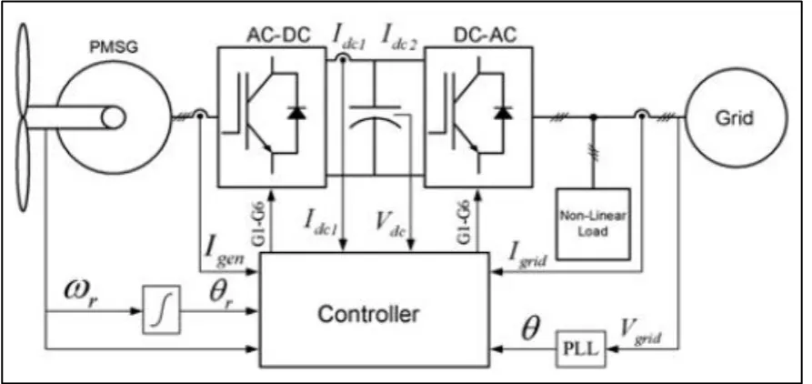
The system under consideration includes a permanent magnet synchronous generator (PMSG) based variable speed wind turbine, a rectifier, an inverter, highly nonlinear load, a common dc link and controllers. The block diagram representation of proposed wind energy conversion system is shown in below figure.
Figure 1 Block diagram of PMSG-based variable speed WECS
WIND TURBINE
The wind turbine converts kinetic energy of wind into mechanical energy. According to Albert Betz “less than 59% of the kinetic energy of the wind can be converted into mechanical energy using a wind turbine”.Operation of wind turbine can be disturbed if voltage, frequency, voltage unbalance and harmonics levels are not within specified limits.Generally, the wind turbines impact on the grid depends on wind turbines characteristics and the gridcharacteristics at the connection point (PCC).A healthy grid can accept more wind turbine without negative consequences on power quality of the system where as weak grids can accept limited number of wind turbines, or the grid has to be reinforced.The relationship between power co-efficient (Cp )and wind power captured by the wind turbine is given by the following equation,
Cp = Pturbine
Pwind (1) Therefore the expression for power captured by the wind turbine is given by,
Pturbine= 0.5 𝜌 𝜋 𝑟2 𝑉𝑤3 Cp (2)
capture high power output, the Cp value should be high. Therefore the selection of optimal value of tip speed ratio and pitch angle is very important.
GENERATOR
Recently the permanent magnet synchronous generator has been gaining more attention compared to other wind energy conversion systems. The advantages of permanent magnet synchronous generators are, compact size, higher power density, reduced losses, high reliability androbustness.
Because of the regular maintenance due to tear and wear of brushes and gear box, the doubly fed induction generators and induction generators eliminated from such applications. Directly coupled low speed generators eliminates the use of brushes and the gear boxes. The nacelle of PMSG without gear box has less weight and there is a reduction of cost of the entire system. Also the efficiency of wind energy conversion system is increased by 10% by the elimination of this gear box. It is possible to represent the dynamic model of permanent magnet synchronous generator in rotating reference frame. In the two phase synchronous reference frame, with respect to the direction of rotation the q axis is
900 ahead of the d axis. With the help of a phase locked loop (PLL) the synchronization between the d-q rotating reference frame and a b c-three phase frame is maintained.
The mathematical model of PMSG in the rotating reference frame in the state equation form is given by,
𝑉𝑞= 𝑅𝑠𝑖𝑞+ 𝐿𝑞 𝑑𝑖𝑞
𝑑𝑡 + 𝑤𝑟𝐿𝑑𝑖𝑑+ 𝑤𝑟𝛌𝑚(3)
𝑉𝑑 = 𝑅𝑠𝑖𝑑+ 𝐿𝑑 𝑑𝑖𝑑
𝑑𝑡 − 𝑤𝑟𝐿𝑞𝑖𝑞 (4)
Where the subscripts d and q refers to direct and quadrature axis quantities, 𝑅𝑠 is the stator resistance in ohm, L is the inductance in henry, 𝛌𝑚 is the magnetic flux in weber, and 𝑤𝑟 is the rotor speed of the generator.
III. DEVELOPMENT OF PROPOSED CONTROL STRATEGY
The proposed control strategy for generator side converter and grid side converter is described in this section.
Generator Side Converter Control
In order to capture maximum power from the wind, variable speed operation of the turbine is necessary. This is achieved with the help of proper control of the wind energy conversion system for the generator side converters. In a variable speed wind energy conversion system, the generator speed and maximum power for different wind velocitiesare cubically related. Therefore in order to maximise the power, the generator should follow power speed characteristics. Hence the generator speed should be controlled.The reference speed for the power speed characteristics is from the power at the dc link. The difference between actual speed and referencespeed is given to the proportional integral (PI) controller.As the speed controlling variable of the rotor speed is „𝑖𝑞‟, the PI controller output is reference for „𝑖𝑞‟.The expression for the reference torque is given by,
𝑇𝑒∗ = (𝐾𝑝𝑤 + 𝐾𝐼𝑤
𝑆 ) (𝑤𝑟 ∗− 𝑤
𝑟) (5)
Where 𝐾𝑝𝑤 = proportional gain for generator speed control&𝐾𝐼𝑤 = Integral gain for generator speed control The expression for torque controlling or q-axis reference current component is given by,
𝑖𝑞∗ = 4 3(
𝑇𝑒∗
𝑃𝛌𝑚) (6)
the d-axis reference current is set to zero. It helps to obtain maximum torque at minimum current. Hence it leads to reduction of resistive losses in the generator.
Fig (2) Simulink model for PMSG control
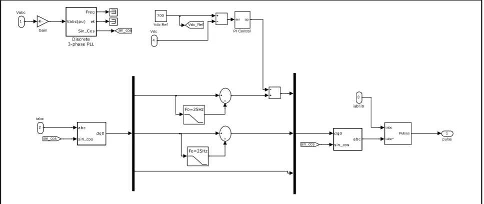
GRID SIDE CONVERTER CONTROL
The grid side converter is an inverter, which convert dc to ac and then it is transferred to grid. The main objective of grid side converter is to deliver captured power with required reactive power compensation and harmonic minimization. Simulink model developed for Grid side converter is shown in below figure.The active power control is done by the outer loop. The outer loop is called dc voltage control loop, which sets the reference current. This reference current is used for active power control. Similarly the inner loop is a current loop, which is required to meet the demand of nonlinear load for reactive power and harmonic compensation at the point of common coupling.The synchronous rotating reference frame is used to realize the proposed control strategy.In this synchronous rotating reference frame the filtering and controlling is very easy because the control variables are dc quantities.With the help of the voltage phase angle 𝜃the above equations are transformed into a-b-c reference voltages. The phase lock loop (PLL) technique is used to extract the grid synchronizing phase angle.
Fig (3) Simulink model for grid side converter control
IV.SYSTEM MODELLING IN MATLAB/SIMULINK
This section includes the complete modelling of wind energy conversion system.At this stage of modelling, a battery bank is employed in order to reduce power fluctuation in the inverter output. The battery bank is connected to the
1 pulse
dq0
sin_cos abc abc
sin_cos dq0
700
Vdc Ref
Iabc
Iabc* Pulses
err op
PI Control Vdc_Ref
sin_cos
-K-Gain
sin_cos sin_cos
Vabc(pu) Freq
wt
Sin_Cos
Discrete 3-phase PLL
Fo=25Hz Fo=25Hz 4
Vdc
3
iabfiltr
common dc link for compensating the power fluctuations. Also the proposed system is able to store the energy during off load conditions. This power can be used for electric vehicles. Hence atmospheric pollution due to transportation as well as generation can be reduced simultaneously.
Fig (4) Simulink model of wind energy conversion system with a battery bank
V. SIMULATION RESULTS
The proposed control strategy for PMSG based variable speed WECS is simulated MATLAB/SIMULINK under different operation conditions are explained here. This section includes the traces of wind speed, tracking of wind speed by PMSG, simulation results of grid active and reactive power, load active and reactive power, inverter active andreactive power and current output of the proposed system.
Fig (a) Tracking of reference speed by PMSG
The controlled rotor speed by regulators based on reference speed of PMSG is shown in the above graph. It is observed that the generator follows exactly the reference speed. This power output is maximum because it follows the power speed characteristics of the generator.
Discrete, Ts = 5e-006 s.
powergui Vabc Iabc A B C a b c Vpcc V ab c Iab c
A B C a b c
Vabc Iabc A B C a b c Vload g A B C + -A B C A B C Plots + -PMSG A B C Non-Linear Load 1 i + -Idc Vabc iabc iabf iltr pulse
Grid side control A B C Grid Idc Iabc VabcL VabcF Vdc IabcL Vabc pulse iabcF IabcL pulse Vabc iabcF + -EV
0 1 2 3 4 5 6 7 8 9 10
0 50 100 150 200 250 300 350
Time (S)
Sp ee d (r ad /se c)
Fig (b) Power output of PMSG
The active power require for the nonlinear load is shown in below graph. This nonlinear load consists of fundamental component, reactive component and harmonic component. The inverter and grid together need to supply this 3 components of nonlinear load.
Fig (c) Required active power of load
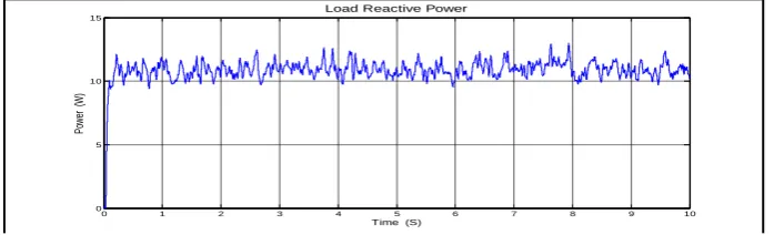
Similarly the reactive power required for the nonlinear load is obtained in the below graph. Usually the reactive component is controlled by quadrature axis component𝑖𝑞. Because the dc link voltage constant, then the reactive component varies according to 𝑖𝑞.
Fig (d) Reactive power required for the load
The active power supplied by the grid in order to meet the requirement of the nonlinear load is shown in below figure. From the below graph it is observed that the active power supplied by the grid is not sufficient meet the requirement of nonlinear load. The active power produced by the PMSG together with grid is also not sufficient to meet this demand.
0 1 2 3 4 5 6 7 8 9 10
0 50 100 150 200 250 300 350
Time ( S )
P
o
w
e
r
(
W
)
Generator output
0 1 2 3 4 5 6 7 8 9 10
0 500 1000 1500 2000 2500
Time (S)
Po
we
r
(W
)
Load Active Power
0 1 2 3 4 5 6 7 8 9 10
0 5 10 15
Time (S)
Po
w
er
(
W
)
Fig (e) Active power supplied by the grid
The reactive power supplied by the grid is shown in the below graph. This is also less than the requirement of the nonlinear load. So the inverter output should be capable to meet the active and reactive component of power according to the requirement of load.
Fig (f) Reactive power supplied by grid
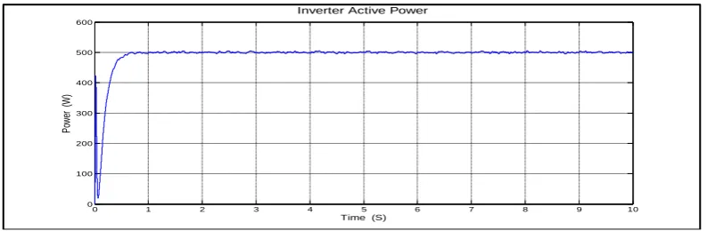
The generator is producing maximum power according to the reference speed. But that power is fluctuating because of the variable nature of the wind. So in order to remove that power fluctuation, we are using that battery bank in the proposed system. So inverter is capable of deliver power without power fluctuation.
Fig (g) Inverter power output
0 1 2 3 4 5 6 7 8 9 10
0 500 1000 1500 2000 2500 3000 3500 4000 4500
Time (S)
Po
w
er
(
W
)
Grid Active Power
0 1 2 3 4 5 6 7 8 9 10
0 5 10 15 20 25
Time (S)
Re
act
ive
P
ow
er
(
Va
r)
Grid Reactive Power
0 1 2 3 4 5 6 7 8 9 10
0 100 200 300 400 500 600
Time (S)
P
ow
er
(
W
)
The reactive power supplied by the inverter is represented in below graph. In order to extract the harmonics a low pass shunt active filter is used. The reactive component varies according to quadrature axis component𝑖𝑞 and active component varies according to𝑖𝑑.
Fig (h) Reactive power supplied by the Inverter
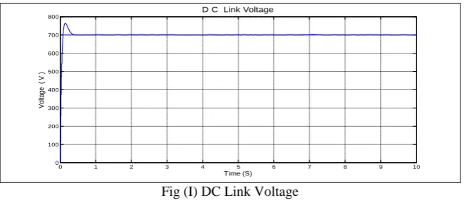
From the above graphs it is observed the remaining power required for the load is provided the inverter with the help of battery system. The battery system is able to provide and absorb the power from the grid, and hence the power fluctuation in the grid is minimized. The dc link voltage is represented in the below figure.
Fig (I) DC Link Voltage
After using the grid side converter control, the inverter current is shown in the below. This current satisfies the requirement of active, reactive and harmonic component of the load. It helps to maintain unity power factor operation with minimal harmonic pollution.
Fig (j) Current output of Inverter
Fig (j) Inverter current
0 1 2 3 4 5 6 7 8 9 10
0 5 10 15 20 25
Time (S)
Po
w
er
(
Va
r)
Inverter Reactive Power
0 1 2 3 4 5 6 7 8 9 10
0 100 200 300 400 500 600 700 800
Time (S)
V
ol
ta
ge
(
V
)
D C Link Voltage
0 1 2 3 4 5 6 7 8 9 10
-15 -10 -5 0 5 10 15
Time (S)
C
ur
re
nt
(
A)
VI.CONCLUSION
The PMSG based wind energy conversion system is modelled in MATLAB/SIMULINK and equations are used to explain its behaviour. Under varying wind conditions the performance of PMSG based wind energy conversion system is demonstrated. The proposed regulator incorporates grid synchronisation of wind energy system. The PMSG is able to track the wind speed exactly with the help of proposed controller. The grid side converter is able to transfer the capture power to nonlinear load at the PCC with minimal harmonics distortion and required reactive power compensation. The system works satisfactorily under normal as well as dynamic condition.The battery bank is connected to the common dc link for compensating the power fluctuations. The grid side inverter is able to inject sinusoidal current at unity power factor. Also the proposed system is able to store the energy during off load conditions and this power can be used for electric vehicles. Hence atmospheric pollution due to transportation as well as generation can be reduced simultaneously.
ACKNOWLEDGMENT
The authors sincerely acknowledge the support and guidance from faculty members of Department of Electrical and Electronics Engineering, University BDT college of Engineering, Davangere to carry out this work.
REFERENCES
[1] M. Singh, V. Khadkikar and A. Chandra ”Grid synchronization with harmonics and reactive power compensation capability of a permanent magnet synchronous generator-based variable speed wind energy conversion system”, IET Power Electron., Vol. 4, Issue. 1, pp. 122–
130,2011.
[2] Z. Chen, and E. Spooner,” Grid Power Quality with Variable Speed Wind Turbines” IEEE Transactions On Energy Conversion, Vol. 16, No. 2, June 2001
[3] G. Lakshmi Narayana and Brave Kumar, “Improvement of Voltage Profile in A Radial Distribution System with Variable Speed Wind Turbines” International Journal of Engineering Research and Applications (IJERA), Vol. 2, Issue 3, pp.880-884,May-Jun 2012.
[4] „IEEE standard for interconnecting distributed resources with electric power systems‟, IEEE15471, 2005
[5] Saccomando G, Svensson J and SanninoA,„Improving voltage disturbance rejection for variable-speed wind turbines‟,IEEE Trans. Energy Convers., 17, pp. 422–428,2002.
[6] JOHNSON G.: „Wind energy systems‟ (Prentice-Hall, Englewood Cliffs, NJ, 1990)
[7] Slootweg J.G,De Haan S.W.H, Polinder H and Kling W.L,„General model for representing variable speed wind turbines in power system dynamics simulations‟, IEEE Trans. Power Syst., pp. 144–151,2003
[8] Westlake A.J.G, Bumby J.R and Spooner E, „Damping the power angle oscillations of a permanent magnet synchronousgenerator with particular reference to wind turbine applications‟, IEE Proc. Electra. Power Appl.,143,1996
[9] P. Kundur, “Power System Stability and Control”, New York: McGraw-Hill, 1994.
BIOGRAPHY
Surya N.Sreceived her AMIE in Electrical Engineering from Institution of Engineers India (IEI), Kolkata in 2011 and she is currently doing M.Tech in Power System Engineering University BDT College of Engineering, Visvesvaraya Technological University, Belgaum, India. Her research is focused on the control of power converters, especially when employed for renewable energy systems. Her major interest includes Power quality, power system voltage stability, reactive power compensation and harmonic minimization problems.