An Adaptive Beamforming Time With Round Robin
MAC algorithm for reducing energy consumption in
MANET
Vincenzo Inzillo1,, Floriano De Rango1,•, Alfonso Ariza Quintana2,†and Amilcare F. Santamaria1,?
1, University of Calabria, DIMES; [email protected]
1,• University of Calabria, DIMES; [email protected]
1,? University of Calabria, DIMES; [email protected]
2,† University of Malaga; [email protected]
Version October 24, 2018 submitted to Preprints
Abstract:The use of Smart Antenna Systems (SAS) in pervasive environments such the Mobile Ad 1
hoc Networks (MANET) has been promoted as the best choice to improve Spatial Division Multiple 2
Access (SDMA) and throughput. Although directional communications are expected to provide great 3
advantages in terms of network performance, directional MAC (Medium Access Control) protocols 4
introduce several issues. One of the most known problems in this context is represented by the fact 5
that, attempting to solve or at least mitigate the problems introduced by these kinds of antennas 6
especially at MAC layer, a large amount of energy consumption is achieved ; for example, due to 7
excessive retransmissions introduced by very frequently issue such as deafness and handoff. The 8
expedients proposed in order to reduce these drawbacks attempting to limit beamforming time of 9
nodes in cooperation with a Round-Robin scheduling, can grant high performance in terms of fairness 10
and throughput. However the overall energy consumption in the network is not efficent due to the 11
static approach. In view of this, we propose an Adaptive Beamforming Time with Round-Robin 12
MAC providing for a dynamic assignment of the beamforming time with the purpose to limit the 13
waste of energy of nodes. 14
Keywords: Smart Antenna Systems, MANET, MAC, Energy Consumption, Beamforming, Round 15
Robin 16
1. Introduction 17
In the latest research studies, relating to wireless network environments, one of the most significant 18
and, at the same time, critical issue is represented by the management of energy consumption of nodes 19
that could highly limit the overall network performance with reference to protocols and application 20
fields. In this regard, several aspects should be considered in order to address the problems implied by 21
main features of this kinds of networks that significantly affect the behaviours at physical, Medium 22
Access Control (MAC) and routing layers. For instance, let us consider Mobile Ad hoc Networks 23
(MANET); they are self-organized networks in which mobile nodes can move independently; the 24
nodes usually move according to a certain mobility pattern model and the movement of a node is not 25
necessarily related to the movement of other nodes in the network. Usually, in MANET, omnidirectional 26
antennas are used for communication among nodes both for transmission as well as for reception; 27
this approach results in very limited performance relating to physical, link and routing layer statistics 28
[1-3]. Omnidirectional antennas, also known as isotropic antennas, radiate and receive equally well 29
in all directions. Main advantages of omnidirectional antennas include: ease of configuration and 30
implementation, low designing cost, very and simple architecture (hardware-less). For instance, in 31
cellular systems, they allow to amplify cell signals from multiple carriers with different cell towers in 32
multiple locations. Nevertheless, despite from these few benefits they introduce a considerable number 33
of drawbacks such as: limited range and coverage (implied by low gain), high energy consumption, 34
high interference probability (especially in dense networks), very high performance dependency on the 35
environments in which they are employed (indoor or outdoor); nonetheless, omnidirectional antennas 36
cannot exploit the benefits of cross-polarization because they are vertically polarized. More specifically, 37
this last issue, contributes to increase the probability of interference between communicating nodes 38
in the channel [4]. From a topological point of view, this approach implies that, the signal generated 39
from the transmitterT, reach desired users with only a small percentage of the overall energy sent out 40
into the environment. Due to this huge number of limitations, omnidirectional antennas may not be 41
efficient due to interference caused by the transmission of packets in all directions (other than target 42
direction) and limited range of communications. 43
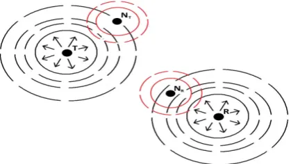
Figure 1.Interference caused by omnidirectional antennas.
The Figure 1 illustrates a wireless network scenario in which nodes use omnidirectional 44
antennas to perform communications. In particular, the transmitter nodeT sends to the receiver 45
Ra communication signal by using an omnidirectional antenna;Rattempts to capture the signal with 46
the same antenna model. Because the transmitter signal is radiated in all directions with the same 47
intensity, if there are such nodes in the neighboring of the transmitter/receiver (NTandNR) is possible
48
that the radiated signal is captured by these nodes that, in turn, may attempt a communication at 49
the same time. In this case, interferences and collisions can occur; these issues could enhance as the 50
mobility of nodes increases. Nevertheless, in this case, because nodes radiate in the same way toward 51
all directions, a huge waste of the battery life of nodes is certainly achieved. The majority of these 52
issues could be partially mitigated using directional antennas. Directional antennas may be useful 53
to increase network efficiency by directing the transmitted power in the desired/intended direction. 54
Directional antennas have a great number of advantages over omnidirectional antennas in ad hoc 55
networking. By focusing energy only in the intended direction, directional antennas can increase the 56
potential for spatial reuse and can provide longer transmission and reception ranges for the same 57
amount of power. Increased spatial reuse and longer range translates into higher ad hoc network 58
capacity (more simultaneous transmissions and fewer hops), and longer range also provides improved 59
connectivity [5-7]. Different kinds of issues have to be investigated when directional communications 60
occur with respect to the traditional omnidirectional case; problems such as the hidden terminal and 61
the deafness problem have to be properly handled as well as handoff issue implied by mobility of 62
nodes. 63
(a) Deafness problem (b) Handoff problem
Referring to directional MAC communications in which Directional Request to Send (DRTS) and 64
Directional Clear to Send (DCTS) are used to perform a transmission/reception flow, a particular 65
node (deaf node) that is engaged in a certain communication, but at the same time is solicited as 66
receiver by another source node arises the deafness problem (Fig. 2(a)). The node that experiences the 67
deafness (the nodeAin Fig. 2(a)) could try to retransmit many times MAC layer packets, resulting 68
in a large amount of collisions and considerable increase of the network overhead. Furthermore, 69
due to the recurring retransmission attempts from deaf node, a large waste of energy could take 70
place, and consequently this node consumes its battery life in a very short time, highly degrading 71
the overall throughput of the network. Another common issue while using directional antennas is 72
given by the handoff problem that is usually implied by the mobility of nodes in the network. In 73
Fig. 2(b) an example of handoff is illustrated: the transmitter nodeTis communicating with a node 74
R; during the communicationRmoves in the positionR’and exit out of the transmitter beam and 75
consequently the communication fails and the beams need to be re-pointed. In this case, if the node 76
in the positionR’ can still be reached byT through a beam switching. If a proper mechanism of 77
synchronization and node position refreshing is not provided, the directional beam remains tuned for 78
a long time in an undesired direction due to node movement; for this reason, again, a lot of energy 79
consumption occurs. Most researchers, in order to mitigate these undesired phenomena in directional 80
contexts, demonstrated that, through the employment of Smart Antenna Systems (SAS) instead of the 81
more traditional directional antennas, it is possible to create an efficient system, exploiting the Spatial 82
Division Multiplexing (SDMA) technique that this kind of devices well provided. Using SAS, higher 83
spatial reuse and better link reliability can be achieved [8-9]. In contexts in which directional Smart 84
Antenna Systems are used, the beamforming issue have to be deeply investigated. The use of DRTS and 85
DCTS frames in association with a Directional Network Allocator Vector (DNAV) information, helps 86
to decrease the large amount of collisions that usually occurs when using omnidirectional antennas, 87
but in environments in which SAS are employed it might not be enough to provide these expedients 88
[10-12]. In the present paper, we propose to reduce these issues by enhancing the works proposed in 89
[13-14] using SAS along with a Round-Robin scheduling in order to address more detailed challenges 90
such as the queue and the time slice problem involved by the use of the Round-Robin. The main 91
purpose of the work is to limit the massive energy consumption in the network and, simultaneously 92
to improve the overall performance when Directional MAC protocols are executed in medium-high 93
mobility environments. 94
2. State of Art 95
Relating to MAC layer communications, the most causes of excessive energy consumption in 96
mobile network scenarios include the use of omnidirectional antennas, data processing, high protocol 97
overhead, high level of interferences in the channel. Data processing implies the large usage of Central 98
Processing Unit (CPU), memory, hard drive, etc. To partially solve this issue the most actual solution 99
is to find a tradeoff on energy consumption between data processing and radio communication [16]. 100
For example, data compression techniques are introduced in [15] to minimize packet length and so to 101
obtain an energy saving in radio communication, but the cost of computation is increased. In work 102
[17] authors also highlight the large protocol overhead introduced by this kind of systems. Generally, 103
to make a MAC protocol energy efficient, at least one of the following guidelines are used: 104
• Reducing collisions and retransmissions:One of the most common objective of MAC protocols 105
in order to avoid collisions so that two interfering nodes do not transmit at the same time. The 106
simplest ways for collision avoidance in a general network include code division multiple access 107
(CDMA), time division multiple access (TDMA), and frequency division multiple access (FDMA). 108
Since collision avoidance may translate into a substantial overhead, which will burn more energy, 109
tradeoffs must be explored to achieve reasonable solution. 110
• Reducing overhearing: Wireless mobile nodes deplet battery life because they overhear the 111
receivers. One possible solution to this problem is the introduction of a control channel for 113
the transmission of control signals that will wake up the nodes only when needed. Authors 114
in [18] propose to broadcast a schedule that contains the data transmission starting times for 115
each mobile nodes. In work [19] two schemes are proposed in order to mitigate the deafness 116
caused by persistent hearing of data and for handling the Short Retry Limit (SRL) in directional 117
environments. 118
• Minimize control overhead: Protocol overhead should be reduced as much as possible, 119
especially for transmitting short packets [20-22]. Due to the large channel acquisition overhead, 120
small packets have disproportionately high energy costs. When mobile nodes request multiple 121
transmission slots with a single reservation packet, the control overhead for reservation can be 122
reduced [23]. A packet delivery scheduling algorithm and two MAC protocols in which nodes 123
uses directional sectorized antennas are proposed in [24]. The scheduler and the protocols are 124
designed with the purpose to prevent the co-site interference problem that could arise in some 125
directional contexts also by limiting the overall overhead in the network. 126
• Reducing beamforming time:In [25] authors, propose a Tone DMAC mechanism that enable 127
the transmission of special packets (Out-of band tones) by nodes in omnidirectional mode; these 128
tones can be processed by neighbors reducing considerably the large backoff time introduced by 129
deafness. In [14] a sectorized antenna model based on a round-robin scheduling algorithm 130
is presented in order to reduce the impact of the deafness in directional communication 131
environments. The Round-Robin mechanism was implemented by an algorithm, that manages 132
the assignment of the beam toward a certain sector also handling the incoming frames that could 133
not temporally be transmitted in the channel (in case they are outside from the current active 134
sector) by using wait queues. 135
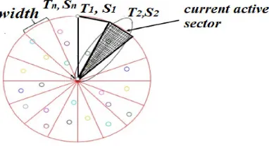
Figure 3.Round-Robin MAC principle.
The Figure 3 illustrates the Round-Robin MAC (RR-MAC) principle. The plane is divided intoN 136
equal sectors, each one having a certain amplitude w (sector width) and a beamforming duration 137
timeTi (sector time) withi= 1...N;Nis the number of sectors in which the plane is divided.
138
Note that all sectors have the same width as well as the same sector time; each node that belongs 139
to a certain sector beamforms with an angleαiuntil the sector time is reached, then it switches to
140
the next sector. The sector in which the beam is currently active is defined current active sector. 141
2.1. Mobility issues directional MAC works 142
Other approaches, such as the work [26], attempt to reduce the handoff issue through an efficient 143
beam system control; a similar work is presented in [27]; in this paper, authors try to mitigate the 144
handoff problem by proposing a predictive location model in order to advance the future position 145
movements of the nodes. Nevertheless, these works are suitable for Vehicular ad Hoc Network 146
(VANET) environments and do not properly address the deafness problem which is very relevant in 147
MANET. In [28] we introduce a predictive location mechanism that also provides for a frame scheduler 148
with priority in order to reduce the handoff problem. However, in this case, the energy consumption 149
3. Omnidirectional and Directional antennas vs Round-Robin MAC 151
As largely mentioned in the previous sections, networks containing nodes equipped with 152
omnidirectional antennas are prone to high waste of energy because the shape of the radiation pattern 153
that does not beamform only a specific direction. Although different proposals there exist with the 154
aim to solve or at least, mitigate the issues derived from the use of omnidirectional and directional 155
antennas at MAC layer, a more deeply analysis is required for highlighting the issues that need to be 156
addressed. For example, let us consider the work [14], that attempts to mitigate the overall network 157
energy consumption using a SAS antenna module along with a Round-Robin scheduler algorithm. 158
Basically, it works fine under two main assumptions: 159
Assumption 1. nodes are equipped with high-efficient hardware antennas (SAS). 160
Assumption 2. data traffic and nodes are uniformly distributed among sectors. 161
Assumption 3. the size of the sector queues are fixed and equals for all sectors. 162
In order to evaluate the implications of the first assumption it can be useful to analyze the behavior 163
of the RR-MAC in case the omnidirectional antenna is used in place of directional or SAS technologies. 164
For this purpose, we evaluate, through the use of theOmnet++Network simulator [29], the energy 165
consumption of nodes of three different run configurations using the same simulation parameters 166
described in [14] (the most of the them are illustrated in table 1 in subsection 5.2 of the present paper); 167
in order to accomplish the analysis, energy simulation modules have been inserted into each mobile 168
node for allowing the emulation of the battery life time behavior. The initial energy value of each node 169
was set to 300 J, the shutdown energy value was set to 0 J; in this way, a node shutdowns when a 170
node completely depletes its battery life. In the first configuration run nodes are equipped with the 171
classical omnidirectional antenna; in the second, nodes use the omnidirectional antenna together with 172
the RR-MAC scheduling; the latest run configuration is similar to the second except from the fact that 173
in this case the antenna is the SAS module designed in [30]. 174
Figure 4.Residual capacity progression.
The Figure 4 depicts the residual capacity (averaged by all nodes) plot comparison between the 175
three considered cases. As we can expect, when using the omnidirectional antenna without any energy 176
saving mechanism, nodes deplet their battery life very quickly; when the omnidirectional antennas 177
are used in cooperation with RR-MAC the average depletion time is almost doubled (t=190 s) and 178
improves significantly when SAS are employed by nodes. This is mainly due to the fact that RR-MAC 179
limits the beamforming time for each sector translating into a reduction of the number collisions and 180
interferences. Then, we investigate about the assumptions 2 and 3. In particular, these assumptions 181
imply that the system could be affected from the queue size and the waiting queue time problems [31] 182
that can affect the overall network consumption in the network. We analyze these issues by creating 183
scenario; also the activity degree of the nodes is uniformly distributed among sectors; in the second, 185
instead, nodes are periodically concentrated in a certain sector (randomly chosen) of the sectorized 186
plane and the activity degree of nodes is unbalanced among sectors. The number of sectors in the 187
plane varies from 3 to 8 while the queue size is evaluated based on the following equation: 188
Queue size=Q×[N+wQ(Ns)] wQ∈WQ (1)
The queue size is function of the number of nodes N and the number of sectorsNsin the plane.
189
Q is a value chosen in the interval 0.1≤ Q≤ 0.25 in order to maximize the Packet Delivery Ratio 190
performance of [14]. The number of sectors is weighted by the termwQthat varies from 1 to 6 as the
191
number of sector value increases. In particular, given the number of sector arrayS= [3, 4, 5, 6, 7, 8], the 192
weight vectorWQis expressed by:
193
WQ= [1, 2, 3, 4, 5, 6] (2)
In order to assess the impact of the two simulation scenarios relating to the queue issues, we 194
compare the waiting queue time of the two running configurations in function of the number of sectors 195
and queue size. 196
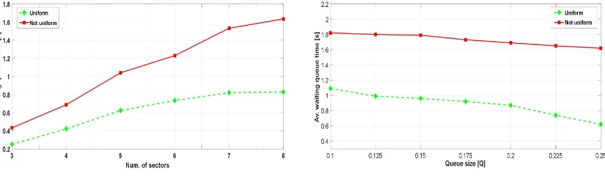
(a) Average waiting queue time vs number of sectors (b) Average waiting queue time vs Queue size
Figure 5.Queue issues with Round-Robin scheduling.
The Figure 5 illustrates the average waiting queue time in function of the number of sectors. 197
The waiting queue time is averaged by varying theQparameter from 0.1 to 0.25. In Fig. 3 it can be 198
observed that the waiting queue time in the case of not uniform distributed nodes remains higher than 199
the uniform case independently from the number of sector value; in particular, the gap between the 200
waiting queue time of the two considered cases seeks to grow for sector number values higher than 201
5. The curves in Fig. 4 are plotted in function of theQparameter that represents a properly index 202
of the queue size; as it can be deduced from eq. 1, the higher is theQvalue, the higher is the queue 203
size. As it happens in Fig. 3 the waiting queue time in the case of not uniform traffic lies above the 204
uniform case curve independently from the queue size. However, as opposed to Fig.3, the difference 205
between curves has kept almost constant as the queue size increases. In the uniform traffic case it can 206
be noted how the waiting time slightly decreases for the highest values ofQwhile, in the not uniform 207
case, the decrease corresponding to the same values is closely negligible. In summary, as the size of 208
the queue grows up the waiting time in the not uniform case does not tend to get smaller, or rather, 209
the decreasing related to high queue size values is not significant. The trends evaluated in Fig. 5 are 210
certainly justified by one of the most common issues implied by a Round-Robin algorithm scheduling: 211
the time slice problem [32-33]; basically, the time slice represents the quantum assigned to each sector 212
(the sector time) in equal portions; therefore, the communications are handled in a circular way among 213
sectors without priority. In case of not uniform distributed traffic if most of mobile nodes are focused 214
in a specific sector of the plane, the communications related to that nodes are enqueued until the beam 215
largest is the waiting queue time. In the same way, as observed in [14] if the quantum assigned to each 217
sector is too low, the system will provide bad performance in terms of overall throughput; a similar 218
behavior is produced if the quantum assigned to each sector is averaged in a specific interval with 219
increasing the number of sectors which results in largest waiting queue time values as seen in Fig. 3. 220
4. Proposed model 221
4.1. Comparison with RR-MAC and motivations 222
As explained in the section 3 the main challenges related to the RR approach are referred to the 223
size of the queues and the delay produced by static time slices which cannot be modeled in function 224
of the traffic in the network. However, as observed in [13, 14] the quantum of time assigned for the 225
beamforming process is the same for each sector as well as the amplitude of the width. Therefore, 226
in the work [14] emerges that a proper set of the sector time value affects the overall performance 227
more than the sector width choice; this implies that time slot assigned to sectors needs to be carefully 228
assigned in order to improve the system efficiency. For these reasons we propose an approach that 229
modifies the original Round-Robin algorithm formulation relative to the evaluation of the sector time 230
while keeping unchanged the sectorization of the plane and thus the width of the sectors. In order to 231
understand the modifications introduced with respect to the Round-Robin MAC algorithm we briefly 232
recall the mathematical formulation of this latter: 233
αi=αj =....=α Ti=Tj=....=Ts
αi(Ti) =αj(Tj) =....=α(T)
∀i,j=1, 2..N, i6=j
(3)
From formulation given by Eq. 3 it is easy to observe that all sectors have the same width and 234
the same sector timeTs. The use of this approach helps to enhance the MAC performance in terms of
235
reduction of collisions and fairness improving, resulting in a overall decrease of the total amount of 236
energy wasted by nodes. Unfortunately, RR-MAC is a static model and does not adapt itself to the 237
traffic channel conditions; this could represent a limit in scenarios in which nodes are concentrated 238
in a certain sector as verified in the previous section. The goal of the present work is to improve the 239
efficiency of the Round-Robin scheduler in terms of energy management by providing an adaptive 240
beamforming time for each sector that takes into account the size of the waiting queue for each 241
sector. We denoted this novel approach as Adaptive Beamforming Time with Round-Robin MAC 242
(ABT-RRMAC). To figure out the relevance of using an adaptive sector time assignment let us consider 243
the situation discussed in sec. 3 in which two different mobile nodes traffic distribution (uniform and 244
not uniform) in the network are compared: 245
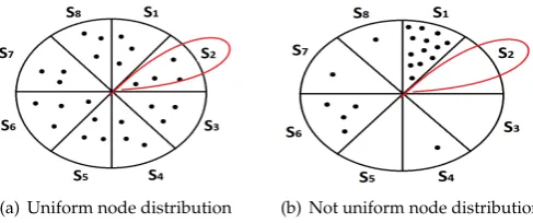
(a) Uniform node distribution (b) Not uniform node distribution
Figure 6.Uniform node distribution vs not uniform using Round-Robin approach.
The Fig. 6(a) represents a network scenario in which mobile nodes are almost uniformly 246
scheduling; therefore, the current active sector is the sector 2, then the beam is active in that sector. As 248
noticed from the analysis accomplished in sec. 3, assuming a uniform activity degree of nodes, in this 249
case, the waiting queue time is acceptable as well as the MAC layer performance; in Fig. 9b it can be 250
observed that the overall node distribution is unbalanced among sectors as well as the activity degree 251
of nodes. More specifically, most of the mobile nodes are mainly distributed in the sector 1 which, 252
as assumption, has also the highest activity degree among sectors; supposing that the current active 253
sector is again the sector 2 and that sector contains a very small number of nodes with respect to the 254
sector 1 together with a very low burden of active communications, it may occur an under-use of the 255
allocated resources in that sector; in particular, due to the static sector time reservation assignment 256
provided by the Round-Robin algorithm (the assigned sector time is the same for all sectors), the 257
overall beamforming process becomes inefficient resulting in a considerable decreasing of the MAC 258
performance especially in terms of throughput and energy consumption. Indeed, in Fig. 6b it is easy 259
to observe that, due to unbalanced disposition of nodes among sectors, the energy consumption in 260
sectorsS2,S3,S4,S5,S7,S8(representing the 80% of the overall plane) is quite inefficient because the 261
beam, in that sectors is performed for a timeTsthat is much higher than the required quantum of time
262
required for emptying the queues. Important to highlight that, because we are analyzing the worst 263
condition case, we assume that the scenarios illustrated in Fig. 6(b) remain unchanged for a long time 264
or change very slowly. 265
4.2. ABT-RRMAC formulation 266
In light of the previous considerations our ABT-RRMAC approach modifies the original Round 267
Robin algorithm formulation regarding the evaluation of the sector time without affecting the plane 268
sectorization and thus the width of the sectors. Basically, the idea is to assign a portion of time for each 269
sector that is proportional to the size of the queues, that in this case is not fixed for each sector and can 270
vary dynamically. 271
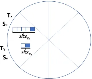
Figure 7.Adaptive Beamforming Time RR-MAC example.
In Figure 7, an example of the ABT-RRMAC application is shown. The plane is normally sectorized 272
into equals amplitude sectors as well as the Round Robin MAC. However, in this case, we consider 273
traffic pattern that is not uniformly distributed among nodes; in Fig. 7, it is assumed that, two particular 274
sectors denotedSxandSyrespectively have different size of the frame waiting queues; in this regard,
275
the termsizeqi denotes the size of the waiting queue related to thei-thsector. While considering the
276
situation in Figure 7, assuming thatTXandTYare the beamforming (sector) times related to the sector
277
T1=
sizeqi
∑N
i=1sizeqi ×T6=Ts ...
... TN=
sizeqN
∑N
i=1sizeqi ×T
⇒T16=T26=..6=TN ⇐⇒ sizeq1 6=sizeq2 6=..6=sizeqN
Where: 279
T= N
∑
i=1 Ti
N (4)
The termTdenotes the mean beamforming time averaged by all sectors. Initially, the beamforming 280
times are the same for all sectors and set toTs(RR-MAC); after a training phase set to 10 s (the time
281
of convergence of the RR-MAC), the mean beamforming time and then sector times are updated 282
periodically in order that for each sector is assigned a quantum of time that is proportional to the size 283
of the queue of that sector multiplied by the mean beamforming time. In this way, sector times can be 284
different and unbalanced among them and the major fraction of time is assigned to the sector having 285
the biggest queue size. For instance, if we consider the example of Figure 7, becausesizeqx >sizeqy
286
then the ABT-RRMAC will assign sector times such thatTX>TY. The motivation of this choice is
287
due to fact thatsizeqx >sizeqy the serving queue rate ofSX is lower than the serving queue rate ofSY;
288
consequently,SXneeds for a beamforming time higher thanSYin order to empty its queue. Among
289
other things, this choice will optimize the energy consumption of nodes in the network; in fact, the 290
undesired waste of energy caused by the classic Round-Robin due to the static model is limited by the 291
dynamic beamforming time assignment. 292
4.3. ABT-RRMAC implementation 293
The ABT-RRMAC algorithm is implemented in the Omnet++ Network Simulator in the 294
DcfUpperMACmodule, that is the main class in which the most important operations at MAC layer are 295
provided, such as frame and collisions management; therefore, as explained in [14] the sectorization of 296
the plane is managed by the SAS antenna module (PhasedArraymodule). The following pseudo-code 297
enhances the original Round-Robin MAC formulation: 298
Algorithm 1ABT-RRMAC pseudo-code (part 1) 1: procedureINIT(numSectors)
2: numQueues←numSectors
3: CREATEQUEUES(numQueues) 4: end procedure
1: procedureASSIGNSECTORTIME(trainingPeriod,updatePeriod,numQueues) 2: ifSim.Time () < trainingPeriod || Sim.Time()< updatePeriodthen
3: averageSectorsTime=0; 4: fori=1; i< numQueues; i++do
5: sectorTime[i] =Ts;
6: end for
7: else
8: averageSectorsTime=computeAverageSectorsTime()
9: fori=1; i< numQueues; i++do
10: sectorTime[i] = sizeqi
∑N i=1sizeqi
×averageSectorsTime; 11: end for
12: end if
Algorithm 2ABT-RRMAC pseudo-code (part 2) 14:procedureSTARTTRANSMIT(frame)
15: int frameSector=getFrameSector(frame); 16: int currentActiveSector=getCurrentActiveSector(); 17: ifcurrentActiveSector != frameSectorthen
18: queueSector[f rameSector].insert(f rame)//queuethe f rame
19: else
20: transmissionQueue.insert(frame);
21: transmitFrame←queueSector[activeSector].f ront()
22: queueSector[activeSector].pop()
23: CONFIGUREANTENNA(activeSector) 24: end if
25:end procedure
1: procedureSTARTRECEPTIONSTATE
2: CONFIGUREANTENNA(omnidirectional) 3: MAC in reception Mode
4: SCHEDULEEVENT(CSMATimer) 5: end procedure
1: procedureRECEPTIONFRAME(frame) 2: orientation←GETORIENTATION(f rame)
3: sector←GETSECTOR(orientation)
4: CONFIGUREANTENNA(sector) 5: end procedure
1: procedureRECEIVEFRAMEFROMUPPERLAYERS(frame) 2: sector←GETSECTORFRAME(f rame)
3: queueSector[sector].push_back(f rame)
4: end procedure
1: procedureMACPROCCESS
2: INIT(NumSectors) 3: STARTRECEPTIONSTATE
4: loop
5: WaitEvent
6: ifEvent Is Upper Framethen
7: RECEIVEFRAMEFROMUPPERLAYERS(frame) 8: else ifEvent Is Lower Framethen
9: RECEPTIONFRAME(frame) 10: else ifEnd Transmissionthen
11: STARTRECEPTIONSTATE
12: else ifEndCSMA∧QueueSector6=emptythen
13: STARTTRANSMIT(frame) 14: else
15: STARTRECEPTIONSTATE
16: end if
17: end loop
18:end procedure
At the beginning of the process, after the plane is sectorized into equal width sectors, the same 299
quantum of time is assigned for all sectors (Round-Robin). If the trainingPeriodhas elapsed the 300
averageSectorsTimedenoting the mean beamforming time averaged by all sectors, can be computed; 301
remember that this parameter is updated periodically after anupdatePeriod(that we set to 10 s) has 302
passed; from the first time that theaverageSectorsTimeis computed, the beaforming times of the sectors 303
are assigned according to expression given by Equation 4. The whole of these operations are included 304
inAssignSectorTimefunction. The transmission of frames is ruled byStartTransmitfunction in which 305
the system checks if the sector for which is destined the current frame is thecurrent active sector. If true, 306
it inserts the frame in the transmission queue and transmit the frame, otherwise the frame is queued in 307
reception of the frame is performed byReceptionFrameandReceiveFromUpperLayersfunctions in which, 309
the receiver antenna is configured in omnidirectional mode and the information about the orientation 310
of the transmitter antenna is retrieved in order to achive the synchronization during communication 311
process. Other coordination functions are performed byMacProcessprocedure. 312
5. Performance evaluation 313
In order to evaluate the contribution of the ABT-RRMAC we perform simulations by considering 314
three different configurations of antennas in the nodes: omnidirectional with Round-Robin scheduling, 315
SAS with Round-Robin (RR-MAC), and our proposed ABT-RRMAC that uses SAS adaptive array 316
antennas; Simulations are accomplished by varying the number of sectors and then, node mobility 317
speed. The following table summarizes the main simulation parameters: 318
Table 1.Main simulation parameter set.
Parameter Value
SAS Array Elements Spacing 0.5λ
Steering angle 45◦
Transmission Rate 54Mbps
Message Length 512Byte
Mobility model Random Waypoint
Node Mobility speed from 1 to 10 mpsmps
Routing Protocol AODV
Network Load 50 %
Simulation Area Size 500 x 500m
Simulation Time 300s
Number of Sectors 3,4,6,8
Initial battery capacity 300 J
Simulations have been accomplished by using 20 different seeds and extracting the confidence 319
intervals obtained by the repetitions considering a confidence level set to 95 %. The traffic is represented 320
by UDP (User Datagram Protocol) data packets randomly generated (based on the simulation seed) by 321
different couples of nodes. The number of nodes is set to 50 and couples of nodes involved in the data 322
traffic exchange is one half with respect to the total number of nodes in the network. In addition, the 323
channel is moderately affected from noise (-80 dBm), with SAS that have the main beam towards 45◦. 324
For the first set of simulations we consider an unbalanced distribution of data (worst conditions) traffic 325
by concentrating the main fraction of communications in the first sector of the plane; therefore, nodes 326
move very slowly (2 mps) in the network and the size of the queues is set to 5. The first evaluated 327
statistic is the energy consumption of nodes by varying the number of sectors. 328
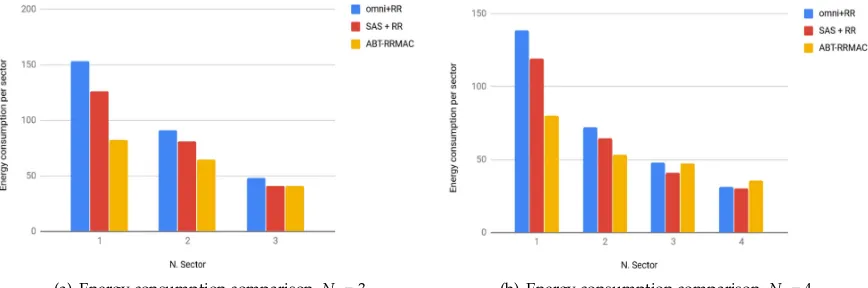
(a) Energy consumption comparison,Ns= 3 (b) Energy consumption comparison,Ns= 4
(a) Energy consumption comparison,Ns= 6 (b) Energy consumption comparison,Ns= 8
Figure 8.Energy consumption per sectors vs number of sectors (part 2)
The plots in Figure 8 illustrate the energy consumption of nodes (expressed in Joule) in function 329
of the number of sectors (observe that the term "N. Sector" used in plots of Figure 8 is related to the 330
progressive number id assigned to each sector and does not identifyNs). In Fig. 8(a) it can be observed
331
how the main fraction of consumption is related to the sector 1, that is the sector in which the traffic is 332
mostly focused with respect to others. When omnidirectional antennas and the Round Robin scheduler 333
are used the distribution of energy consumption among sectors is very unbalanced; this trend is 334
mainly due to the static time slot assigned by the scheduler, that, in this case is the same of all sectors; 335
this feature results in a not efficient distribution of the energy in the sectors and consequently, the 336
total energy consumption is considerable (almost 298 J). However, the same behavior is maintained 337
in Fig. 8(b) in which, when SAS module are used it can be highlighted a better distribution of the 338
consumed energy among sectors. In Fig. 8(c) it appears clear, how, as the number of sector increases 339
the maximum amount of consumed energy is reduced, but in the case of omnidirectional antennas 340
the imbalance remains unchanged; however the use of the SAS allows to decrease considerably the 341
maximum energy amount that is further reduced when ABT-RRMAC approach is employed (44,54 342
against 88,27 registered in the omnidirectional case). Finally, the Fig. 8(d) emphasizes even more 343
the impact of the proposed approach flowing in a overall balancing of the energy consumption. In 344
summary, the dynamic allocation of the beamforming time allows, independently from the number of 345
sectors, to optimize the distribution of the energy also leading to a reduction of the overall consumed 346
energy; indeed the registered values of total consumed energy in the RR-MAC case in function of the 347
number of sectors are 248.33, 255.14, 250.91 and 272.32Jagainst values of 187.89, 216.26, 211.81 and 348
235.37Jregistered when ABT-RRMAC is used. For a further investigation, it is possible to evaluate the 349
standard deviation (averaging values by sectors) of the energy consumption by increasing the number 350
of sectors for all of the configurations: 351
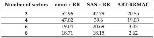
Table 2.Energy consumption: standard deviation vs number of sectors.
Number of sectors omni + RR SAS + RR ABT-RRMAC
3 52.96 42.79 20.55
4 47.02 39.6 19.03
6 19.04 20.69 3.03
8 18.71 18.15 2.62
The Table 2 collects standard deviation values by varying number of sectors for all of the 352
considered approaches; the use of SAS slightly enhances the omnidirectional case, however, observe 353
how ABT-RRMAC contributes to dramatically decrease values when the number of sectors improves 354
with respect to other considered configurations; this trend confirms that our proposed approach seeks 355
Therefore, energy consumption is very related to Packet Delivery Ratio (PDR) and could represent an 357
helpful indication of the overall network performance; for this purpose next figure illustrates PDR 358
comparison extracted byrcvdPktsandsentPktsstatistics collected by Omnet++: 359
(c) Average PDR vs Num. of sectors (d) Average PDR vs Queue size
Figure 9.Packet Delivery Ratio comparison.
In Figure 9, the average (averaged with respect to nodes) PDR is plotted both in function of the 360
number of sectors and the queue size. The Fig. 9(a) simply reflects the situation verified in Figure 8, in 361
fact, the lowest is the energy consumption the highest is the PDR; therefore, when the number of sector 362
is high, ABT-RRMAC is able to provide a PDR of about 0.92 against 0.85 registered in the RR-MAC 363
configuration. The same statistic can be evaluated by increasing the size of the queues; in Figure 9(b) 364
(values are averaged with respect to number of sectors) it seems clear that PDR performance are quite 365
sensitive to queue size, indeed, low moderately values of PDR are obtained when omnidirectional 366
antennas are used; SAS contributes to increase the minimum PDR from 0.62 to 0.72, however the 367
minimum PDR value, when our proposed approach is used, is 0.84; this value slightly improves 368
together with the queue size and tends to begin almost uniform for highest queue size values. More 369
specifically, especially for critical queue size cases (from 3 to 5) the difference between RR-MAC and 370
ABT-RRMAC is very significant; this result suggests that our proposed algorithm provides for a great 371
robustness also when the queue size are small, allowing quite acceptable performance in case of limited 372
resource allocation. The latest set of simulations is accomplished with the aim to test our proposal 373
in condition of mobility of nodes; for this purpose we evaluate the energy consumption of nodes by 374
increasing the node mobility speed from 1 to 10mps; in this case, results are obtained by averaging 375
energy consumption values with respect to number of sectors. In addition, we compared the worst 376
queue size case (queue size = 3) and the best queue size case (queue size = 10). 377
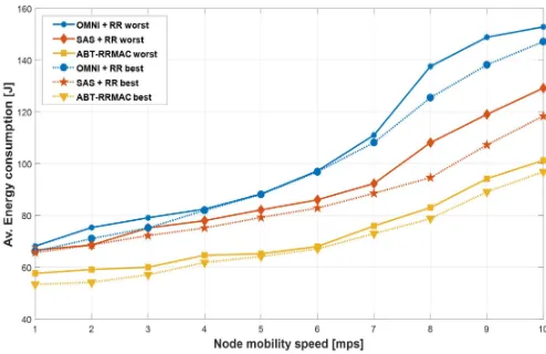
Figure 10 displays comparison curves related to energy consumption of nodes in function of 378
the mobility speed by considering the worst and the best registered case in function of the size of 379
the queues. Note that continued-line curves depict the worst case plots while dashed-line curves 380
are related to the best case plots. As regards omnidirectional case, the overall consumption remains 381
tolerant until 7mpsand then whereupon increases widely; this is mainly due to link failures occurring 382
for high mobility speed values that results in enhancement of protocol overhead. However this 383
rapid increase is weak limited in the best omnidirectional case. When using SAS in cooperation 384
with Round-Robin, disruptive impacts due to growth of node mobility speed, are quite mitigated 385
with respect to omnidirectional case, especially for high mobility values. Therefore the effects of 386
directional high-gain beamforming are quite straightforward; in particular, by considering the best 387
and worst cases, the energy saving amount in the case of RR-MAC gives from 23 to 29 J compared to 388
omnidirectional. Nevertheless, ABT-RRMAC, thanks to dynamic sector time assignment, improves, 389
performance of RR-MAC extending battery life of nodes of about 21% (on average) compared to the 390
latter. This effect seems to keep uniform also as the mobility speed of nodes grows up. Note that, for 391
ABT-RRMAC curves related to best and worst case are almost overlapped, indeed, the effect of queue 392
size results mitigated compared to other considered cases. 393
6. Conclusions 394
We proposed an Adaptive Beamforming Time with Round-Robin MAC approach with the goal 395
to improve benefits in terms of energy consumption introduced by the employment of Round-Robin 396
scheduling in directional antenna MANET contexts [14]. This work has been mainly motivated by the 397
fact that, although a RR approach is able to counteract main directional antenna issues which usually 398
can occur at MAC layer, the energy consumption distribution is not well distributed among sectors. 399
Basically, the unbalanced energy distribution, due to problems introduced by Round-Robin such as the 400
time slice and queue issues, promotes a not negligible waste of energy which can lead to limit the overall 401
network performance especially in terms of Packet Delivery Ratio. In order to attempt to mitigate these 402
problems, we proposed a solution which aims to eliminate the static assignment of the beamforming 403
(or sector) time for sectors that could bring to a not efficient energy distribution among sectors. The 404
presented solution provides of a dynamic assignment of the beamforming time by considering the 405
current size of the sector queues and the average beamforming time; all parameters are updated 406
periodically. The main advantage of that dynamic assignment is that, when data traffic is unbalanced 407
in the simulation scenario, the slowest is a certain sector to empty its queue (that is directly related to 408
the size of the queue) the highest is the quantum of time assigned to that sector. The ABT-RRMAC 409
has been compared to the classic omnidirectional MAC exploiting the Round-Robin principle and 410
with the RR-MAC presented in [13-14] that uses SAS instead of omnidirectional antennas. Results, in 411
terms of energy consumption of nodes, by considering different configuration cases related to number 412
of sectors, have shown how ABT-RRMAC is able to reduce of about 37% on average, the maximum 413
energy consumption amount per sector, with respect to RR-MAC and even 50% compared with 414
omnidirectional case; furthermore, our proposed approach contributes to level the energy consumption 415
of nodes by uniformly distributing the total amount among sectors. For a further investigation, PDR 416
of all considered cases has been evaluated in function of the number of sectors and queue size; with 417
reference to queue size ABT-RRMAC provides for a minimum PDR of 0.84 that considerably improves 418
the value of 0.72 obtained in RR-MAC. This result is significant because reduce the dependency of 419
the PDR with queue size. Finally, our approach has been evaluated in terms of energy consumption 420
by considering mobility of nodes; in this regards, result have been highlight that ABT-RRMAC 421
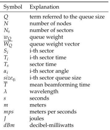
Table 3.List of symbols used in this manuscript
Symbol Explanation
Q term referred to the queue size N number of nodes
Ns number of sectors
wQ queue weight
WQ queue weight vector
Si i-th sector
Ti i-th sector time
Ts sector time αi i-th sector angle
sizeqi i-th sector queue size
T mean beamforming time
λ wavelength
s seconds
m meters
mps meters per seconds
J joules
dBm decibel-milliwatts
Abbreviations 423
The following abbreviations are used in this manuscript: 424
425
SAS Smart Antenna Systems MAC Medium Access Control OMNI Omnidirectional
DMAC Directional Medium Access Control RR-MAC Round Robin MAC
ABT-RRMAC Adaptive Beamforming Round Robin Medium Access Control MANET Mobile ad Hoc Network
VANET Vehicular ad Hoc Network SDMA Spatial Division Multiple Access DRTS Directional Request to Send DCTS Directional Clear to Send
DNAV Directional Network Allocator Vector CPU Central Processing Unit
FDMA Frequency Division Multiple Access TDMA Time Division Multiple Access CDMA Code Division Multiple Access SRL Short Retry Limit
PDR Packet Delivery Ratio
AODV Ad Hoc On Demand Distance Vector 426
References 427
1. Dai, Hongning; Kam-Wing, Ng; Min-You, Wu; An overview of MAC protocols with directional antennas 428
in wireless ad hoc networks.In Proceedings of Wireless and Mobile Communications, ICWMC’06. International 429
Conference on. IEEE2006. 430
2. Huang, Zhuochuan; Chien-Chung, Shen; A comparison study of omnidirectional and directional MAC 431
protocols for ad hoc networks.In Proceedings of Global Telecommunications Conference, 2002. GLOBECOM’02. 432
IEEE. Vol. 1. IEEE, 2002. 433
3. Andyopadhyay, S.;Roy, S.; Ueda, T.; Enhancing the performance of ad hoc wireless networks with smart 434
4. Suhag, S.; Gupta, A.; Duhan, M.; Improvement of QoS Parameters by using Directional Antennas in MANET. 436
International Journal, 5(6),2016. 437
5. Kumari, N.; Kumar, R.; Bajaj, R.; Energy Efficient Communication Using Reconfigurable Directional Antenna 438
in MANET.Procedia Computer Science, 125,2018, pp. 194-200. 439
6. Kumai, N.; Kumar, R.; Bajaj, R.; Mobile ad hoc networks and energy efficiency using directional antennas: A 440
Review.In Proceedings of Intelligent Computing and Control Systems (ICICCS), 2017 International Conference on 441
IEEE, 2017, pp. 1213-1219. 442
7. Jiang, D.; Xu, Z.; Li, W.; Chen, Z; Network coding-based energy-efficient multicast routing algorithm for 443
multi-hop wireless networks.Journal of Systems and Software, 104,2015, pp. 152-165. 444
8. Patra, S.; Pandey, A.; Nandni, N.; Kumar, S.; Jha, V.; Kumar, M.; Power pattern synthesis of smart antenna 445
array using different adaptive algorithms.International Journal of Advanced Research, 3(5),2015, pp. 1459-1466. 446
9. He, C.; Liang, X.; Zhou, B.; Geng, J.; Jin, R; Space-division multiple access based on time-modulated array. 447
IEEE Antennas and Wireless Propagation Letters, 14,2015, pp. 610-613. 448
10. Niu, J.; Zhang R.; Cai L.; Yuan J.; A Fully-Distributed MAC Protocol for Mobile Ad Hoc Networks. In 449
Proceedings of International Conference on Communications, 2015. 450
11. Wang, G.; Xiao, P.; Li, W.; A novel MAC protocol for wireless network using multi-beam directional antennas, 451
In Proceedings of International Conference on Computing, Networking and Communications, 2017. 452
12. Wang, J.; Ren, X.; Chen, F. J.; Chen, Y.; Xu, G.; On MAC optimization for large-scale wireless sensor network, 453
Wireless Networks,2016. 454
13. Inzillo, V.; De Rango, F.; Quintana, A. A.; A sectorized directional MAC proposal for mitigating deafness and 455
energy consumption in mobile ad hoc networks.In Proceedings of Consumer Communications and Networking 456
Conference (CCNC), 15th IEEE, 2018, pp. 1-2,. 457
14. Inzillo, V.; De Rango, F.; Santamaria, A. F.; Quintana, A. A.; A round-robin MAC approach for limiting 458
deafness in mobile ad hoc network beamforming environments.In Proceedings of Wireless Days (WD) IFIP, 459
2018, pp. 98-100. 460
15. Jones, C.; Sivalingam, K.; Agrawal, P.; Chen J.; Survey of energy efficient network protocols for wireless 461
networks.Wireless Networks Vol.7 No.4,2001, pp. 343-358. 462
16. Chou, J.; Petrovic, D.; Ramchandran, K.; A distributed and adaptive signal processing approach to reduce 463
energy consumption in sensor networks,In Proceedings of INFOCOM, 2003. 464
17. Wei, Y.; Heidemann, J.; Estrin, D.; An energy-efficient MAC protocol for wireless sensor networks,In 465
Proceedings of INFOCOM, 2002. 466
18. Sivalingam, K.; Chen, J.; Agrawal, P.; Strivastava, M.; Design and analysis of low-power access protocols for 467
wireless and mobile ATM networks,Wireless Networks, Vol.6 No.1,2001, pp. 73-87. 468
19. Gossain, H.; Cordeiro, C.; Cavalcanti, D.; Agrawal, D.;. The deafness problems and solutions in wireless 469
ad hoc networks using directional antennas. In Proceedings of IEEE Global Telecommunications Conference 470
Workshops , GlobeCom IEEE, 2004, pp. 108-113. 471
20. Huang, P.; Xiao X.; Soltani, S.; The evolution of MAC protocols in wireless sensor networks: A survey.IEEE 472
communications surveys and tutorials 15.1,2013, pp. 101-120. 473
21. Huang, Z.; Chen, Y.; Li, C.; PSR: A lightweight proactive source routing protocol for mobile ad hoc networks. 474
IEEE Transactions on vehicular technology 63.2,2014, pp. 859-868. 475
22. Haider, M.; Knightly, M.; Mobility resilience and overhead constrained adaptation in directional 60 GHz 476
WLANs: protocol design and system implementation.In Proceedings of the 17th ACM International Symposium 477
on Mobile Ad Hoc Networking and Computing, ACM, 2016. 478
23. Chen, J.; Sivalingam, K.; Agrawal, P.; Acharya, R.; Scheduling multimedia services in a low-power MAC for 479
wireless and mobile ATM networks.IEEE Transactions on Multimedia, Vol.1 No.2,1999, pp. 187-201. 480
24. Swaminathan, A.; Noneaker, D. L.; Russell, H. B.; The design of a channel-access protocol for a wireless ad 481
hoc network with sectored directional antennas.Ad Hoc Networks, Elsevier, 10(3),2012. 482
25. Choudhury, R. R.; Vaidya, N. H.; Deafness: a MAC problem in ad hoc networks when using directional 483
antennas.In Proceedings of IEEE International Conference on Network Protocols (ICNP), Berlin, Germany, 2004, 484
pp. 283-292. 485
26. De la Chapelle, M; Monk, A.; Soft handoff method and apparatus for mobile vehicles using directional 486
27. Lu, X.; Lio, P.; Hui, P.; Jin, H.; A Location Prediction Algorithm for Mobile Communications Using Directional 488
Antennas.International Journal of Distributed Sensor Networks,2013. 489
28. Inzillo, V.; De Rango, F.; Quintana, A. A.; Zampogna L.; Mobility Beamforming Prediction and a Round Robin 490
Scheduling in a Directional MAC for MANET.In Proceedings of Wireless and Mobile Networking Conference 491
(WMNC),IFIP, 2018. 492
29. Omnet++ Simulator, Vers. 5.2,www.omnetpp.org, 2018. 493
30. Inzillo, V.; De Rango, F.; Quintana, A. A.; A Low Energy Consumption Smart Antenna Adaptive Array 494
System For Mobile Ad Hoc Networks.International Journal of Computing, 16(3),2017, pp. 124-132. 495
31. Abdullah, A. A.; Cai, L.; Gebali, F; DSDMAC: dual sensing directional MAC protocol for ad hoc networks 496
with directional antennas.IEEE Transactions on Vehicular Technology, 61(3),2012, pp. 1266-1275. 497
32. Jha, J.; Chowdhury, S.; Ramya, G.; Survey on various scheduling algorithms, Imperial Journal of 498
Interdisciplinary Research 3 (5),2017. 499
33. Fataniya, B., Patel, M.; Survey on different method to improve performance of the round robin scheduling 500