Design and Implementation of Navigation and
Combat Ship
Priyanka Gaikwad
1, Payal Jambhule
2, Sheetal Kekan
3, S.K.Gaikwad
4UG Student, Dept. of ECE, Pimpri Chinhwad College of Engineering, Pune, Maharashtara, India1
UG Student, Dept. of ECE, Pimpri Chinhwad College of Engineering, Pune, Maharashtara, India2
UG Student, Dept. of ECE, Pimpri Chinhwad College of Engineering, Pune, Maharashtara, India3
Professor, Dept. of ECE, Pimpri Chinhwad College of Engineering, Pune, Maharashtara, India4
ABSTRACT: The pattern of this paper comprises of a self-navigating robotic ship(ship spy)as a base on which guided by the computer in the control room and the remote triggered for a weapon is fitted in the ship vehicle. The PIC Controller acts as a crucial scheming element for the ritual built vehicle. The PIC architecture describes a family of RISC-based COMPUTER PROCESSOR. The reduced complexity and simpler design build a low-energy system on chip for an embedded system incorporating memory, interfaces, radios, etc. The ship contains single board embedded system that is equipped with GPS and RF modems along with PIC processor, which in turns the GPS receiver has been interfaced with the vehicle which is capable of receiving information from the GPS satellites and this technology allows the system in finding out the location of the ship in terms of Latitude and longitude coordinates, anywhere on earth and provides most up to date information about ongoing trips. The control room can transmit the targeted location by RF modem technology to the ship in terms of Latitude and longitude data. Once the ship receives this data, the microcontroller unit compares the targeted location with the present location and separately moves to the desired location. Additionally the camera is mounted on the robotic ship, which is in a scanning pattern to capture all the visible details around the ship.The video is transmitted to a control room through RF module, if the presence on enemy is detected the mounted weapon on the vehicle is triggered based on the commands from the control room. The main purpose of this project is to provide following features a)Location information b)Real time tracking c)Communication is instantaneous therefore we can receive running report d)Completely integrated controlled and monitored by control room
KEYWORD:-PIC, GPS Receiver, Wireless Camera, RF modem, LASER GUN.
I.INTRODUCTION
Terrorism, the new face of nation’s fate has exceeded its own state of action. It’s time to uproot terrorism instead to face it and to dedicate the brave hearts to the nation. With the advent growth in the field of Robotics in today’s scenario is tremendous especially in the areas of nation’s security is concerned .As terrorism increasing day by day, its duty of engineer’s to curb it through innovation. Since robots become more advanced and sophisticated it can be used to perform the desired tasks where men cannot be in a state to carry out his tasks. With automation and application of electronics in the field of robotics ensures safety for individuals and desired task can be achieved. This paper set sights on devising and demonstrating an archetype of one guided weapon system which considerably
reduces the people substantially present in the streaks of fire. The objective of our work is to devastate the terror activities. In this paper, the methodology adopted to achieve our objective is to build a powered vehicle with self-navigating design; to turn ON the wireless camera once the vehicle movement is detected; to transmit the real time video signals to control room and to trigger the weapon if necessary.
II.BACKROUND
a small boat alongside the US Navy destroyer in the Yemeni port of Aden, killing 17 American sailors and injuring another 39. India has a coastline of 7500 kilometers with 13 major and nearly 200 minor ports. There are thousands of ships and fishing boats operating in the sea; therefore, it is no easy task to check and monitor their movements. It is clear that enhanced surveillance, gathering and sharing of information, and monitoring of activities at sea are extremely important even at local level. It is important to raise awareness among the coastal community of the possible terrorist threats from the.The occurrence of terrorism by the ocean way serves as a background for the paper.
III.LITERATURE SURVEY
The navigation systems are concerned with the monitoring and controlling the movements of a vehicle/craft in a physical space. For tracking the route, the navigation system utilizes the waypoints information such as presented by Millington et al. [2], in which they utilized the waypoint information for the navigation system in a vehicle. The co-ordinates information are used as route, and the waypoints information and the vehicle position are displayed on the screen with a feedback system for controlling the vehicle moments directions. The use of Global Positioning System (GPS) for the creation of waypoints i.e. set of co-ordinates in physical space for the navigation systems have been proved very effective. In Global Positioning System (GPS) based navigation systems, the trajectory of the vehicle or craft is determined through a series of waypoints and followed by navigating the next waypoints until the destination is reached such as presented in [3,4]. hoi et al. [3] provided autonomous mobile robot using GPS, the robot follows its trajectory with feedback through GPS receiver, and evade obstacles with the help of photo-sensors. Along with this, one can trace a Mobile robot with a wireless RF communication module. Hamid et al. [4] present another navigation system’s implementation in a mobile robot in a different way using GPS for navigation and sonar sensors for obstacle avoidance. The beauty of this work is that they are using command loop daisy changing application method. The similar work is presented in by sukkarieh et al. [5] for land vehicle applications. Their work combines the inertial measurement unit with global positioning system for the enhancement of integrity of the navigation system by considering both the low frequency faults and high frequency faults in inertial measurement unit and PGS respectively during and before the fusion of inertial measurement unit and GPS. Bruch et al. [6] represent a land based navigation system for vehicles implemented on Man Portable Robotic System Urban Robot. This navigation system uses combination of Kalman filter, waypoint and some inexpensive sensors along with the GPS and implemented on an embedded processor
IV. NAVIGATION
The transition of an artificial entity from one coordinate (position) to another is termed as navigation. The GPS based navigation system, originally developed for military purposes is formed from 24 satellites and is the most widely used navigation system all over the world. Nowadays, instead of the militarily usage, the GPS is used in health, communication and different other utilities related to motorcars, airplanes, ships, drones and could be apply to all other moving amenities. The figure 1 shows example of GPS based navigation system.
Many considerations have been made for the selection of GPS module for this particular application. After the study of all choices and considerations, the ship robot designed for this application prefers the use of GTPA003 for GPS receiver. The main reason is that the small size of the GPS receiver makes it light and this is 51 channel GPS receiver designed to operate with L1 frequency and the GPS receiver tracks and uses the signal to compute and update position. There are a number of output formats supported by this GPS receiver; however the proposed work uses the text output format. Text mode is a simple output mode that provides a string containing the information about time, position and velocity.
V.DESIGN
The Robotic-Boat is basically designed to undertake navigation operation. It determines the position and the direction via a GPS Module. The exact location is monitored via GPS. A remote control circuit is designed, which makes manual control of the ship applicable. This is useful in some special circumstances, and thus can increase the practicability of the ship. To realize the functions mentioned above, the designed ship should be controlled by a microcontroller. It should also have power supply system , GPS Module and interface, motion controlling system, circuit for temperature detecting , and remote control system
Fig.2 Block diagram
A.PIC Microcontroller System
The main control is with microcontroller system which has an efficient crystal oscillator, a watchdog timer. We use a pic microcontroller as its efficiency is good. Its basic features must include 32k bytes of on-chip flash memory, 256 Bytes of on-chip RAM, four 16-bit timers/counters, two external interrupt. The oscillating frequency of the microcontroller is 40 MHz. The Watchdog timer reset the computer system on power up, power failure, and other abnormity.
B. Design of the motion control by GPS
robotic-boat is embedded with the GPS Module to provide the exact location of the Vehicle. The GPS location is monitored at the control centre and thus helps in defining the direction for motion, under manual control.
C. Design of the remote control system
The manual control of the ship is achieved via Remote control system. Radio frequency signals are transmitted to achieve the desired control. The ship can be controlled manually via Control-Centre. Its keys include the key to switch between the manual mode and automatic mode, the keys to control the moving directions, and the key to control the,motor that drives the conveyor belt.
D. Design of the motor control system
The DC motor solely powers the boat, including the conveyor belt of the refuse collection and transmission, and the two propellers. The two DC Motors are used to drive the two propellers. As defined earlier five controlling scenarios are designed which include going straight, turning to the left, turning to the right, turning to the left at right-angle and turning to the right at right-angle. This is done by controlling the speed of the Motor. The boat can be turned left at right angle when the left motor is stopped while the right side motor runs at the defined speed. In the contrary, the ship is turning right at right angle.
E.Gun and Camera
It has got two barrel turret through bullet can be fired, radio camera in synchronization with the turret can rotate left and right up to a safe firing limit. Turret and camera mechanism has been installed on my robot vehicle, which has all the function like tank, Turing to any angle on its axis, moving forward and reverse turning left and right, running instantly into reverse direction. This robot is radio operated; self powered, and has all the controls like a normal car. A pair of laser gun has been installed on it, so that it can fire on enemy remotely
F.Transmitter Circuit Explanation
Key data is transmitted through the 433mhz transmitter module through its pin no 3 of the microcontroller which is Tx pin of the inbuilt uart of the microcontroller and works on 1200bits/sec. X1 along with c4 and c5 gives the required clock input to the microcontroller c 1 and r1 forms the reset circuitry
connected to pin no 1 of the microcontroller. Key pressed value is transmitted through antenna.
E. Design of programs
According to the process of the work to undertake navigation, the programs of the main Microcontroller system are designed in a modular structure. The programs of the main Microcontroller system consist of the following modules, program for:
1. Managing the Power System
2. Remote control
3. Communicating
4. Controlling the moving directions
5. Controlling the motors.
VI.RESULTS
TTL signal by using converting circuit. L293d is a dual H-Bridge motor driver, so with one IC interface two DC motors can be interfaced. These motors can be controlled in both clockwise and counter clockwise-direction.
Fig 3.Design model of a proposed system
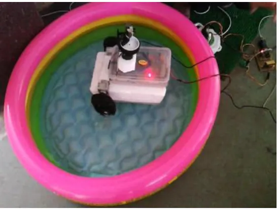
In fig 4 the testing of robot in water is shown. We tested the proposed sytem in water , the robot moves according to the commands given from the transmitter side i.e. from laptop.Also the live footage is recorded by camera and the position of the ship is given by GPS.
Fig 4.Testing of robot in water
VII.FUTURESCOPE
1. Voice communication can be introduced.
VIII.CONCLUSION
In order to strengthen the security and defense of our country we desperately require robotic system which will forearm our defense system. So, we have designed a prototype for a navigation and combat ship. We have thoroughly tested it in water.
REFERENCES
[1] Abhinav Kumar Singh1, Nilaya Mitash Shanker2 & Anand Prakash Yadav3 ,“ RF Controlled Terrorist Fighting Robot ” International Journal of Computer Science & Communication , Vol. 1, No. 1, January-June 2010, pp. 109-112
[2] Jeffrey Alan Millington, Chandiran Palanisamy, Rhonda Marie Paprocki et al. (2004), “Vehicle Nevagation System with Off-Road Navigation”, United States Patent, Patent No. US 6,836,725 B2, date of Patent: Dec. 28, 2004.
[3] Hawan-Seok Choi, Han-Sil Kim (2005), “Autonomous Mobile Robot Using GPS”, proceeding on international conference of control and automation (ICCA2005) Budapest, Hungary, Vol. 2, Pp. 858-862.
[4] MHA Hamid, A,H Adom, NA Rahim, MHF Rahiman (2009), “Navigation of Mobile Robot Using GPS and Obstacle Avoidance System with commanded Loop Daisy Chaining Application Method”, Proceeding on 5th International Colloquium on Signal Processing & its Application (CSPA) Kaula Lumpur, Vol. pp. 176-181.
[5] G.Viswanatha Reddy, E.Venkatramana, Dr.G.N.Kodanda Ramaiah “Unmanned Robotic Ground Vehicle by Using ZIG-BEE and GPS ”, Vol. 3 Issue 1 September 2013 (IJLTET)