Suite 64
Integrated
Communications
Exchange
Flash Voicemail Manual
PCS
digital
Advanced Features
Competitive Pricing
Proven Performance
The information contained in this document is proprietary and is subject to all
relevant copyright, patent and other laws protecting intellectual property, as well as
any specific agreement protecting PCS Digital, LLC. (herein referred to as the
“Manufacturer”) rights in the aforesaid information. Neither this document nor the
information contained herein may be published, reproduced or disclosed to third
parties, in whole or in part, without the express, prior, written permission of the
Manufacturer. In addition, any use of this document or the information contained
herein for any purposes other than those for which it was disclosed is strictly
forbidden.
The Manufacturer reserves the right, without prior notice or liability, to make
changes in equipment design or specifications.
Information supplied by the Manufacturer is believed to be accurate and reliable.
However, no responsibility is assumed by the Manufacturer for the use there of nor
for the rights of third parties which may be affected in any way by the use thereof.
Any representation(s) in this document concerning performance of the
Manufacturerʹs product(s) are for informational purposes only and are not
warranties of future performance either express or implied. The Manufacturerʹs
standard limited warranty, stated in its sales contract or order confirmation form, is
the only warranty offered by the Manufacturer in relation thereto.
This document may contain flaws, omissions or typesetting errors; no warranty is
granted nor liability assumed in relation thereto unless specifically undertaken in the
Manufacturerʹs sales contract or order confirmation. Information contained herein is
periodically updated and changes will be incorporated into subsequent editions. If
you have encountered an error, please notify the Manufacturer. All specifications are
subject to change without prior notice.
© Copyright by PCS Digital, LLC., 2004.
All rights reserved worldwide.
All trademarks contained herein are the property of their respective holders.
Record of Revisions
Catalogue Number Release Date Supersedes Comments
Initial Release April 2005
V1‐I2 Initial Release On page 1‐1, it states that the
voicemail connects using Single
line ports, which is wrong.
On pages, 1‐3, 2‐1,5‐29 and 7‐1 ,
the memory expansion is listed as
3 hours, not 6.
General Clean up of examples
and extension parameters
TOC
Table of Contents
1 INTRODUCTION ... 1‐1
SYSTEM FEATURES... 1-2
Announcement only Mailbox... 1-2 Answering Machine Emulation ... 1-2 Automated Attendant Functions ... 1-2 Automatic Day/Night Mode... 1-2 Automatic Gain Control... 1-2 Cancel Play of Message ... 1-3 Custom Call Routing Menus (Eight) ... 1-3 Customized Greetings ... 1-3 Default Transfer to Operator ... 1-3 Dial by Name Directory (First or Last Name) ... 1-3 Direct Transfer to a Virtual Voice Mailbox ... 1-3 External (Off Net) Call Transfer ... 1-3 Fast Forward .5 Seconds ... 1-3 Fax Tone Detection and Transfer ... 1-3 Message Delete with Confirmation ... 1-3 Message Forwarding with or without Comments ... 1-4 Message (envelop) Information... 1-4 Message Pause and Restart ... 1-4 Message Reply... 1-4 Message Retrieve ... 1-4 Message Rewind .5 Seconds... 1-4 Message Save ... 1-4 Message Waiting LCD/LED or Stutter Tone... 1-4 Multiple Classes of Service (4)... 1-4 One Touch Record... 1-4 Operator Backup... 1-4 Outbound Notification with message pickup... 1-4 Override System Prompts... 1-5 Password Protection ... 1-5 PC Programming ... 1-5 Programming from a Touch Tone® Phone... 1-5 Security Passwords ... 1-5 Skip To Next Message ... 1-5 Transfer Option from Mailbox ... 1-5
INTENDED AUDIENCE... 1-6 BASIC OPERATION... 1-6 DOCUMENT OVERVIEW... 1-7 APPLICABLE DOCUMENTS... 1-7 PREREQUISITES... 1-8
General Information and Disclaimers ... 1-8 Electro-Static Discharge Warning ... 1-9 Hazardous Voltage Warnings ... 1-9 General Safety Guidelines... 1-9 Warranty Limitations ... 1-10 FCC Regulations... 1-10 Warranty Repairs ... 1-11 Document Conventions ... 1-11
2 SYSTEM SPECIFICATIONS... 2‐1
TOC
3 SYSTEM PROGRAMMING ... 3‐1
HYPERTERMINAL SETUP... 3-2 PROCOMM SETUP... 3-3
Procomm for Windows Version 4.7 Up... 3-3
SUITE 64VOICE MAIL PORTS... 3-4 DTMFPROGRAMMING ACCESS... 3-4 PROGRAMMING THE SUITE 64FLASH VOICE MAIL SYSTEM VIA HYPERTERMINAL... 3-5 PROGRAMMING GUIDELINES... 3-6
4 INSTALLATION ... 4‐1
SUITE 64FLASH VOICE MAIL SYSTEM CARD INSTALLATION... 4-2
5 SETUP... 5‐1
UNDERSTANDING THE FLASH VOICE MAIL FLOW... 5-1
SUITE 64FLASH VOICE MAIL SYSTEM STARTUP... 5-2
Initialization and PBX Integration ... 5-4
MENU OPTION 1-OPEN &CLOSE SCHEDULE... 5-6
Field Descriptions... 5-7 Open and Close Schedule Example... 5-7
NAVIGATING CCRMENUS... 5-8 MENU OPTION 2–NUMBER PLAN... 5-9
Field Descriptions... 5-9 Number Plan Example ... 5-11 Single Digit Dialing with Automated Attendant Functions ... 5-13 General Delivery Mailbox... 5-13 Announcement Only Mailboxes... 5-14
MENU OPTION 3-INVALID DIGITS... 5-15 MENU OPTION 4-AUTOMATED ATTENDANT CONFIGURATION... 5-16
Field Descriptions... 5-17
MENU OPTION 5–[FUTURE USE] ... 5-19
MENU OPTION 6-REAL TIME CLOCK... 5-19
Field Descriptions/Detailed Instructions ... 5-20
MENU OPTION 7-VERSION NUMBER... 5-21
Field Descriptions... 5-21
MENU OPTION 8-SET SYSTEM PASSWORD... 5-22 MENU OPTION 9-MAILBOX ASSIGNMENT... 5-23
Field Descriptions... 5-23 Examples of Adding and Deleting Mailboxes ... 5-26
MENU OPTION 10-CLASS OF SERVICE... 5-28 OPTION 11-FREE SECTORS (RECORDING TIME REMAINING... 5-29 MENU OPTION 12-PBXINTEGRATION... 5-30
Field Descriptions... 5-31 PBX Integration Examples ... 5-34 Special Fax Detection Function ... 5-35
MENU OPTION 13-SYSTEM INITIALIZATION... 5-35 MENU OPTION 14-MESSAGES WAITING... 5-36
Field Descriptions... 5-36
MENU OPTION 15-DEBUG INFORMATION SCREEN... 5-37
6 SYSTEM ADMINISTRATOR MAILBOX FUNCTIONS... 6‐1
ENTERING THE SYSTEM ADMINISTRATOR MAILBOX... 6-1 ADMINISTRATOR OPTIONS –DETAILED DESCRIPTIONS... 6-2
TOC
Set Operation Mode [Press 5] ... 6-11 Select PBX Integration [Press 6] ... 6-13 Record a Prompt [Press 7] ... 6-14 Listen to a Prompt [Press 8] ... 6-15 Change Open and Close Schedule [Press 9] ... 6-16
7 OPTIONAL EQUIPMENT... 7‐1
THREE-HOUR EXPANSION MODULE... 7-1 INSTALLATION... 7-2
LOF
List of Figures
FIGURE 1. SUITE 64FLASH VOICE MAIL SYSTEM CIRCUIT CARD (SIDE VIEW)... 4‐1
FIGURE 2. INSTALLATION OF SUITE 64FLASH VOICE MAIL SYSTEM CARD... 4‐2
FIGURE 3. ENTER PASSWORD SCREEN... 5‐2
FIGURE 4. PROGRAMMING MAIN MENU... 5‐3
FIGURE 5. SYSTEM INITIALIZATION SCREEN... 5‐4
FIGURE 6. PBXINTEGRATION SELECTION SCREEN... 5‐5
FIGURE 7. PBXINTEGRATION SCREEN... 5‐5
FIGURE 8. OPEN AND CLOSE SCHEDULE SCREEN... 5‐6
FIGURE 9. SYSTEM NUMBERING PLAN SCREEN... 5‐9
FIGURE 10. NUMBERING PLAN SCREEN EXAMPLE... 5‐11
FIGURE 11. INVALID DIGITS SCREEN... 5‐15
FIGURE 12. AUTOMATED ATTENDANT SETUP SCREEN... 5‐16
FIGURE 13. INTERNAL CLOCK SETTINGS... 5‐19
FIGURE 14. INTERNAL VERSION NUMBER SCREEN... 5‐21
FIGURE 15. PASSWORD SETUP SCREEN... 5‐22
FIGURE 16. MAILBOX ASSIGNMENT SCREEN... 5‐23
FIGURE 17. CLASS OF SERVICE SETUP SCREEN... 5‐28
FIGURE 18. FREE SECTORS SCREEN... 5‐29
FIGURE 19. PBXINTEGRATION SELECTION SCREEN... 5‐30
FIGURE 20. PBXINTEGRATION SCREEN... 5‐31
FIGURE 21. MESSAGES WAITING SCREEN... 5‐36
FIGURE 22. DEBUG INFORMATION SCREEN... 5‐37
1
Introduction
1
1
I
I
n
n
t
t
r
r
o
o
d
d
u
u
c
c
t
t
i
i
o
o
n
n
The Suite 64 Flash Voice Mail System Flash Voice Mail System is a powerful,
compact voice processing system that uses state‐of‐the‐art Digital Signal Processing
hardware and software, interfaced with the PCS digital Flash Voice Mail System
compact communications platform.
There are no moving parts associated with the system as all voice processing uses
digital voice processing chips for the utmost in voice clarity and reliability.
This compact, high‐performance, solid‐state voice processing system is designed to
provide today’s businesses with a feature‐rich system enabling small companies to
project the image of a much larger company. Since a large majority of all telephone
transactions require only one‐way communications, an efficient voice mail function
contributes to streamlining business communications.
The purpose of this manual is to provide the instructions for installing a new Flash
Voice Mail Card in the Suite 64 telephone system and on‐line and operational in the
fastest time possible. Complete programming instructions are described in detail
Introduction
1
System Features
Announcement only Mailbox
Callers can access Mailboxes to listen to pre‐recorded data such as product
information, hours of operation or directions to your location ‐ at their convenience.
These mailboxes will play the greeting then terminate the call. Announcement only
Mailboxes can be used to build a multi‐level menu response system.
Answering Machine Emulation
Mailbox users may listen, in real time, to a caller as a Voice Mail message is being
recorded. In addition, the user can pick up the call and speak with the calling party.
Automated Attendant Functions
The Suite 64 Flash Voice Mail System provides eight (8) Custom Call Routing (CCR)
Menu boxes which may be used to process a call once dialed into the system. Each
port may be directed to a different CCR, if desired. Each of the CCR Menu box
provides an incoming caller with a customized welcome greeting that describes the
actions available to an incoming caller:
Dial an extension number to reach someone.
Press a digit to leave a message in a particular mailbox. (i.e. to collect names and
addresses of interested parties for a brochure mailing.)
Play a specific announcement, such as detailed directions to the company.
Present callers with options to select submenus for different departments. There
are eight CCR Menu boxes available, which may be interconnected as required.
Dial‐by‐Name directory function to locate users by their First or Last name.
Automatic transfer of incoming FAX calls to a local fax extension.
Automatic Day/Night Mode
At a specified time, the Voice Mail system can automatically switch from Open to
Closed operation. This allows companies to customize their day and night greetings,
as well as their Custom Call Routing Menu options.
Automatic Gain Control
Automatically increases the volume when someone is speaking quietly and drops
1
Introduction
Cancel Play of Message
Allows the user to stop a new message from playing while keeping it as a new
message and in the order in which it was received.
Custom Call Routing Menus (Eight)
Custom Call Routing (CCR) Menus are used to process callers once they are
answered by the Voice Mail system. Each CCR can have up to thirteen menu options
and a customized welcome greeting, which generally describes the company’s
message and the different menu options. To further customize the system each port
can be programmed to use the same or different CCR menus.
Customized Greetings
There are ten programmable greetings that can be assigned to one or more CCR,
which provides callers with information and/or instructions after the system has
answered the call.
Default Transfer to Operator
If a caller does not press a digit while after the Voice Mail answers, the call will be
automatically transferred to the operator.
Dial by Name Directory (First or Last Name)
A caller can “Spell” (enter the first letter) a subscriber’s first or last name if they do
not know the extension of the intended party.
Direct Transfer to a Virtual Voice Mailbox
The Voice Mail Administrator may set a virtual Mailbox to transfer callers directly
to the Mailbox.
External (Off Net) Call Transfer
Callers are given the option to dial a digit and be transferred to a preprogrammed
telephone number.
Fast Forward .5 Seconds
While listening to a message, you can fast forward the message by .5 seconds to
speed up the message playback.
Fax Tone Detection and Transfer
If a call is received on a port and fax tones are heard, the incoming call will be
transferred to the programmed Fax Extension.
Message Delete with Confirmation
When deleting a message, a second digit must be pressed to confirm the deletion of
Introduction
1
Message Forwarding with or without Comments
You can forward a message to another subscriber’s Mailbox with or without
comments.
Message (envelop) Information
A prompt may be set to play the date and time to indicate when a message was
delivered.
Message Pause and Restart
While listening to a message, it may be pause and restarted at anytime.
Message Reply
Users may reply to a message sent from another subscriber’s Mailbox.
Message Retrieve
Users may retrieve a voice mail messages from on or off site locations.
Message Rewind .5 Seconds
While listening to a message, you can rewind .5 seconds of the message at anytime.
Message Save
Users may save played messages in their mailbox for future playback.
Message Waiting LCD/LED or Stutter Tone
The system automatically lights extension users “voice mail” button, if programmed,
on their telephone. Single Line Telephones (SLT) will receive “Stutter” dial tone.
Multiple Classes of Service (4)
The system administrator can grant or restrict access to the mailbox features of the
maximum message length, number of allowed messages, and the number of days
that a user may save messages.
One Touch Record
While on a telephone conversation, the user can press a preprogrammed button on
their telephone and record the conversation directly in their voice mailbox for future
use or playback.
Operator Backup
Callers can dial “0” at any time to reach the system operator.
Outbound Notification with message pickup
The system notifies users of waiting messages by calling any remote telephone
number, such as a pager, cellular telephone or home telephone. The mailbox user
1
Introduction
Override System Prompts
Experienced users may execute commands at any time by pressing the digits,
without having to wait for the system prompts to finish playing.
Password Protection
Access to the System Administrator and all individual mailboxes are protected with
user‐programmable passwords.
PC Programming
Terminal programming is done using a laptop or desktop Personal Computer. No
special software is required. Any DOS or Windows communications package that
supports ANSI terminal emulation will work.
Programming from a Touch Tone® Phone
Many features are accessible from a Touch Tone telephone via the System
Administrator with password protection.
Security Passwords
The Terminal and Touch Tone Administration areas and individual mailboxes can
only be accessed after a valid password is entered.
Skip To Next Message
Users may skip to the next new or saved message without listening to the complete
message.
Transfer Option from Mailbox
A mailbox user may set their mailbox to transfer callers directly to their Mailbox or
to the programmed extension number.
Introduction
1
Intended Audience
This manual is intended for a technician responsible for installing and configuring
the Suite 64 Flash Voice Mail System and its related components.
Basic Operation
The Suite 64 Flash Voice Mail System, in its default configuration, is an eight‐port
system with three hours of voice storage that can process eight different callers at the
same time. An additional six hours of recording time can be added with the addition
of the optionally available expansion module. The callers can be any combination of
outside or inside callers. As each caller finishes their call, the port is made available
for the next caller allowing a large number of users can be supported with the Suite
64 Flash Voice Mail System.
The Suite 64 Flash Voice Mail System uses Single‐Digit Commands, eliminating the
need to memorize long key sequences. Once the user is familiar with the system,
they will be able to “dial‐ahead” by knowing the correct commands.
All mailboxes can be accessed from any telephone anywhere in the world as long as
touch tone® dialing is available. To ensure privacy, all mailbox functions are secured
by a password which the user provides when entering their mailbox.
1
Introduction
Document Overview
This manual is arranged in the following sections:
Chapter 1: Introduction‐ this chapter describes the overall capabilities of the Suite 64
Flash Voice Mail System including System Capabilities, Basic Operation, an
overview of this document and prerequisites for installation of the system.
Chapter 2: System Specifications – this chapter lists all of the system specifications.
Chapter 3: System Programming –this chapter describes the programming features
accessible through HyperTerminal and the programming features accessible through
a telephone.
Chapter 4: Suite 64 Flash Voice Mail System Card Installation – this chapter describes
the contents of the Suite 64 Flash Voice Mail System package as well as the
installation procedure of the hardware.
Chapter 6: Suite 64 Flash Voice Mail System Setup ‐ this chapter describes the initial
startup, the uses of the System Setup Screens and the fields within each.
Chapter 7: System Administrator Mailbox Functions ‐ this chapter describes all of the
System Setup features available through the System Administrator mailbox using a
telephone.
Chapter 8: System Prompts Listing – this chapter lists all of the available system
prompts.
Chapter 9: Optional Equipment – this chapter describes the optionally available
equipment available for use with the Suite 64 Flash Voice Mail System.
Applicable Documents
The following documents should be used in conjunction with this manual:
Introduction
1
Prerequisites
Proper preparation is extremely important for a successful installation and will result
in improved customer satisfaction with the Suite 64 Flash Voice Mail System. Taking
a few moments initially to secure the necessary equipment, programming
information, and manpower requirements will streamline the installation, as well as
enhance the customer’s perception of how the new system will work for them.
In order to properly set up the system, you should make sure that the following
items are available before starting the initial setup:
A system Custom Call Routing (CCR) menu design plan that has been discussed
with and approved by the end‐user.
A well‐spoken person available to make the necessary recordings for the system
greetings.
All required documentation for the Suite 64 options programming.
The installation should be carried out early enough in the day to allow sufficient
time for customer changes, integration issues, etc. A good estimate is to allow 3‐4
hours for a complete installation, excluding the necessary time for training the end‐
users.
It is recommended that this Installation Manual be reviewed prior to the installation
date.
General Information and Disclaimers
While this manual contains current Suite 64 Flash Voice Mail System information, its
1
Introduction
Electro-Static Discharge Warning
The Suite 64 Flash Voice Mail System circuit boards are static sensitive. They should
be handled by the edges only and kept in the anti‐static packaging bags until ready
for installation. Do not subject any component parts to static discharge or physical
mishandling. When handling circuit boards, it is advisable to use an anti‐static wrist
strap and cover the work surface with the anti‐static bag used to ship the board.
Static charges should be discharged from the body before touching the boards or
components by touching the grounded metal case of the system power supply unit
or cold water ground connection if available. The product warranty for this
equipment does not cover damage caused by such described static discharges or
mishandling. Any modules or components determined to have been damaged in
such a manner will only be replaced at dealer cost.
Hazardous Voltage Warnings
The equipment purchaser is responsible for protecting the installed equipment from
hazardous voltages. The Suite 64 Flash Voice Mail System was submitted to a
Nationally Recognized Testing Laboratory (NRTL) for safety approvals. Before
installing the equipment, check local electrical codes that apply to the installation of
telephone and electronic equipment. The following safety guidelines are taken from
UL document 1459, Issue 2, which is product safety specification governing
telephone equipment.
General Safety Guidelines
When installing and using telephone equipment, the basic safety precautions
described below should always be followed to reduce the risk of fire and/or
electrical shock:
Read and understand all instructions.
Follow all warnings and instructions that are marked on the product.
Unplug the product from the wall outlet before cleaning. DO NOT apply any
liquid or aerosol cleaners directly to the unit.
Do not use this product near any sources of water or in a wet environment.
Do not place this product on an unstable shelf or table. The product may fall,
causing serious damage to the product. This damage may compromise the
safety features of the equipment. It is recommended to install the Suite 64 Flash
Voice Mail System card by mounting it on a flat, dry wall surface.
Air ventilation openings are provided in the equipment for ventilation to
protect the voice mail from overheating. The Suite 64 Flash Voice Mail System
card should never be placed near or over any type of heating radiator or heat
register. In addition, Suite 64 Flash Voice Mail System card should not be
Introduction
1
Warranty Limitations
The product warranty is limited to replacement of defective components and does
not cover injury to persons or property or other consequential damages.
FCC Regulations
This equipment has been tested by an independent testing lab and found to comply
with the limits for a Class A digital device, pursuant to part 15 of the FCC Rules as
reproduced below:
These limits are designed to provide reasonable protection against harmful
interference when the equipment is operated in a commercial environment. This
equipment generates uses and can radiate radio frequency energy and, if not
installed and used in accordance with the instruction manual, may cause harmful
interference to radio communications. Operation of this equipment in a residential
area is likely to cause harmful interference in which case the user will be required to
correct the interference at their own expense. FCC rulings state that the owner of the
system to be installed gives the local telephone company sufficient advance notice of
intention to use privately owned telephone equipment. The owner must also furnish
information as to the identification of the particular lines to be connected to the
system and the affected telephone numbers. FCC registration information on the
model number, FCC‐assigned registration number and ringer equivalence
information must also be furnished. The ringer equivalence (REN) is used to
determine how many devices can be connected to a telephone line. In most areas,
the sum of RENs of all devices on one line should not exceed five. If too many
devices are attached, they may not ring properly. Should there be any questions that
the customer ‐ provided equipment may cause harm to the telephone network, the
local operating company is required to notify the customer of an impending
temporary interruption of service. The customer must be given the opportunity to
correct the existing problem, if possible. The telephone company must also advise
customers of their rights for filing complaints before the FCC. The telephone
company may make changes in its technical operations and procedures. If such
changes affect the compatibility or use of this system, the telephone company is
required to give adequate notice of the changes. Under no circumstances is the
equipment to be altered or modified without written approval of the manufacturer.
Failure to gain permission for any modification will void the warranty. If a system
malfunction is suspected, the connectors terminating the equipment to the CO lines
1
Introduction
Warranty Repairs
In accordance with the Federal Communications Commission regulations, an
authorized agent must perform any repairs to this equipment.
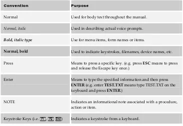
Document Conventions
This manual uses several conventions to convey information more clearly to the
reader. It is recommended that the conventions shown below in Table 1 be reviewed
and understood before continuing.
Table 1 - Document Conventions
Convention Purpose
Normal Used for body text throughout the manual.
Normal, italic Used in describing actual voice prompts.
Bold, italic type Use for menu items, form names or items.
Normal, bold Used to indicate keystrokes, filenames, device names, etc.
Press Means to press a specific key. (e.g. press ESC means to press
and release the Escape key once.)
Enter Means to type the specified information and then press ENTER (e.g. enter TEST.TXT means type TEST.TXT on the
keyboard and press ENTER.)
NOTE Indicates an informational note associated with a procedure,
action or item.
Keystroke Keys (i.e. 1, 9 e) Indicates a keystroke from a keyboard.
2
System
Speci
fications
2
2
S
S
y
y
s
s
t
t
e
e
m
m
S
S
p
p
e
e
c
c
i
i
f
f
i
i
c
c
a
a
t
t
i
i
o
o
n
n
s
s
This chapter describes the specifications of the Suite 64 Flash Voice Mail System.
General Specifications
Processes up to eight calls simultaneously (eight ports).
Connects directly with the Suite 64 cabinet ‐ no additional hardware required.
Allows all features to be accessed via a touch tone® telephone.
Contains 64 regular mailboxes and 16 Announcement Only.
Performs routine mailbox maintenance automatically by re‐synchronizing
mailboxes once per day.
User programming for mailboxes, call routing and selection of the PBX system
for integration.
Three (3) Hours or Nine (9) Hours with optional six (6) ‐ hour Memory
Expansion Card.
Maximum of 64 mailboxes.
Maximum of 999 messages.
Eight Custom Call Routing Boxes.
DSP Processor Operating System.
Serial programming port.
3
System Progr amming3
3
S
S
y
y
s
s
t
t
e
e
m
m
P
P
r
r
o
o
g
g
r
r
a
a
m
m
m
m
i
i
n
n
g
g
All Suite 64 Flash Voice Mail System programming is performed using a laptop or
standard PC desktop system. A subset of programming may be performed using the
System Administrator’s mailbox. Special software is NOT required. Any DOS or
Windows® communications package that supports ANSI terminal emulation will
work properly. The required port speed and protocol is 2400, N‐8‐1.
The cable between the Suite 64 Flash Voice Mail System unit and the PC must be a
straight through, serial cable with a 9‐pin male‐female connector on each end.
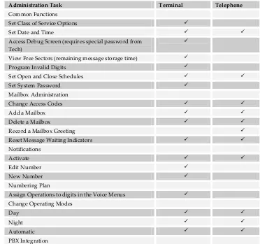
Table 2 ‐ below shows the programming features that are accessible from the
programming PC and those accessible from a touch tone® telephone via the System
Administrator’s mailbox. Refer to Chapter 6 for specific descriptions of the System
Administrator functions.
Table 2 Accessible Program Features
Administration Task Terminal Telephone Common Functions
Set Class of Service Options
Set Date and Time
Access Debug Screen (requires special password from
Tech)
View Free Sectors (remaining message storage time)
Program Invalid Digits
Set Open and Close Schedules
Set System Password
Mailbox Administration
Change Access Codes
Add a Mailbox
Delete a Mailbox
Record a Mailbox Greeting
Reset Message Waiting Indicators
Notifications
Activate
Edit Number
New Number
Numbering Plan
Assign Operations to digits in the Voice Menus
Change Operating Modes
Day
Night
System
Progr
amming
3
Administration Task Terminal Telephone
Set PBX Integration Type
Change PBX Integration parameters
System Prompts
Record Prompts
Review Prompts
Select System Greeting per Port
Day
Night
Temporary
CCR Menu Greetings
Review
Record
Delete
Check Software Version Numbers
HyperTerminal Setup
If using HyperTerminal as the communications package, perform the following steps
before beginning programming:
1. Select Start Programs Accessories Communications HyperTerminal
2. Setup a new connection using the following settings:
a. Select the correct COM port, as required by your PC, then press OK.
b. On the Comport Settings screen, set 2400, N 8 1, Flow Control to XON,
XOFF.
c. Click OK.
d. Click on File Properties, and then select the Settings tab.
e. Select Auto Detect as the emulation.
f. Click on the ASCII setup button and uncheck the “Wrap lines that exceed terminal width” option.
g. Click OK, and then click OK again.
3. The HyperTerminal connection is now configured properly for programming the
Suite 64 Flash Voice Mail System.
4. Exit, and then re‐start the HyperTerminal program.
5. After connecting to the Suite 64 Flash Voice Mail System, press Eto access the
3
System
Progr
amming
Procomm Setup
Procomm Plus for DOS or Procomm Plus for Windows can also be used for
programming. The software will require certain specific parameter settings and
function key mapping. The information below outlines the required changes. Since
different versions of the software may have these parameters in different areas, we
will list the changes that need to be made in your spec will tell you the general area
where the changes need to be made.
It is recommend that you install a separate copy of Procomm in its own subdirectory, since some of the parameter changes may affect how the program interacts with other systems you may program. Make sure to set Transmit Pacing = 0 under A‐S ‐ General Options or the Functions Keys may not operate properly.
Procomm for Windows Version 4.7 Up
Terminal setup (Direct Connect)
Terminal type . . . ANSI BBS
Speed. . . 2400
Parity . . . None
Word length . . . 8
Stop bit . . . 1
Terminal update . . . FAST
Break length. . . 350ms (350 1/10ths of a second)
Terminal scroll method. . . NORMAL
Enquiry type . . . OFF
Terminal size . . . 25 Rows / 80 Columns
XON/XOFF flow control . . . OFF
System
Progr
amming
3
Function Key Mapping
Most versions of Procomm Plus have only the first four function (F) keys mapped to
terminal functions. Each (F) key has four states that can be programmed. You only
need to program the NORMAL state. These settings are found under the Setup
option, Terminal Setup, Keyboard files.
The correct key mappings for
1 - 4
are as follows:1
. . . ^[OP2
. . . ^[OQ3
. . . ^[OR4
. . . ^[OS
Suite 64 Voice Mail Ports
The Suite 64 System reserves one (1) UCD/Hunt Group, dial code 253, for Voice Mail
and it is equipped with eight (8) ports, which are numbered 465 – 472.
DTMF Programming Access
As seen in Table 2 Accessible Program Features ‐ A number of programming
parameters may also be changed using the System Administrator Mailbox. This
mailbox, when accessed, presents a menu of choices which allow the System
Administrator to make these changes.
3
System
Progr
amming
Programming the Suite 64 Flash Voice Mail System via
HyperTerminal
Programming the Suite 64 Flash Voice Mail System requires the entry of values in
specific fields on various programming screens. These programming screens are
accessed from a Programming Main Menu by selecting an item in the menu and
pressing the R key.
Access to Suite 64 Flash Voice Mail System programming is protected by a password to prevent any unauthorized changes to system parameters. The default password is 0‐0‐0‐0.
While working with a particular screen, use the r l b t keys or the R key to
navigate through the fields as required. Once you have changed a given field, you
MUST press the Rkey to save your changes to that field unless otherwise
specified.
The TAB key does not provide any field‐to‐field movement.
When the required programming is finished, type E X I T and press the R key.
This shuts down the programming interface. If you wish to re‐enter the
programming screens, you will be required to enter the System Password again.
System
Progr
amming
3
Programming Guidelines
Organization is very important when setting up the Suite 64 Flash Voice Mail
System. You should have all the pertinent information such as mailboxes, menu
plans, etc. gathered BEFORE starting the installation.
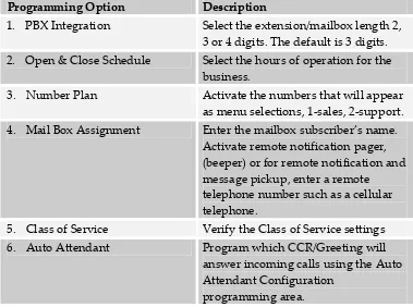
Table 3 ‐ below indicates the flow of programming only. Detailed programming
steps are contained in the next few chapters.
Table 3 Recommended Programming
Programming Option Description
1. PBX Integration
Select the extension/mailbox length 2, 3 or 4 digits. The default is 3 digits.
2. Open & Close Schedule Select the hours of operation for the
business.
3. Number Plan Activate the numbers that will appear
as menu selections, 1‐sales, 2‐support.
4. Mail Box Assignment Enter the mailbox subscriber’s name.
Activate remote notification pager, (beeper) or for remote notification and message pickup, enter a remote telephone number such as a cellular telephone.
5. Class of Service Verify the Class of Service settings
6. Auto Attendant Program which CCR/Greeting will
answer incoming calls using the Auto Attendant Configuration
programming area.
4
Installation
4
4
I
I
n
n
s
s
t
t
a
a
l
l
l
l
a
a
t
t
i
i
o
o
n
n
This section describes the installation of the Suite 64 Flash Voice Mail System card
into the Suite 64 bus.
Each Suite 64 Flash Voice Mail System is shipped with the following items:
Flash Voice Mail System circuit card
Installation & Maintenance Manual
Mailbox Owner User Guide
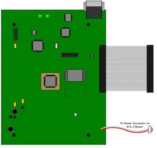
An illustration of the Suite 64 Flash Voice Mail System circuit card is shown below in
Figure 1.
Figure 1 Suite 64 Flash Voice Mail System Circuit Card
Installation
4
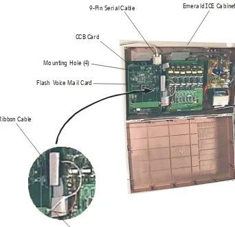
Suite 64 Flash Voice Mail System Card Installation
The Suite 64 Flash Voice Mail System card is installed above the Common Control
Board (CCB), using the supplied standoffs.
To avoid damaging system components be sure to power down the Suite 64
prior to installing Flash Voice Mail System card.
Figure 2 Installation of Suite 64 Flash Voice Mail System Card
Emerald ICE Cabinet 9-Pin Serial Cable
CCB Card
Flash Voice Mail Card Mounting Hole (4)
4
Installation
1. While holding the card close to the Suite 64 cabinet;
a. Connect the ribbon cable with the pin connector, labeled VAA, on the
CCB
b. Connect the red/white power line connector into the power plug on the
Main Board (610‐2)
2. Place the card on top of the Common Control Board and affix it with the four (4)
supplied standoffs. To avoid damaging the card, Do not over tighten the
standoffs; a good rule of thumb is to make them “Figure Tight”.
3. Turn the Suite 64 cabinet power on and verify that the green LED’s, showing
System Status, at the top of the card are alternately blinking.
a. Upon power up the system will:
i. Create hunt group 24 (253), with members 465 ‐ 472
ii. Establish all programming to integrate the KSU with the voice
mail system.
4. Connect a 9‐pin serial cable male‐end to the female receptacle on the Suite 64
Flash Voice Mail System card.
5. Connect the other end of the serial cable with the desired serial port on a laptop
or PC.
The Suite 64 Flash Voice Mail System is now installed, integrated and ready for
5
Setup
5
5
S
S
e
e
t
t
u
u
p
p
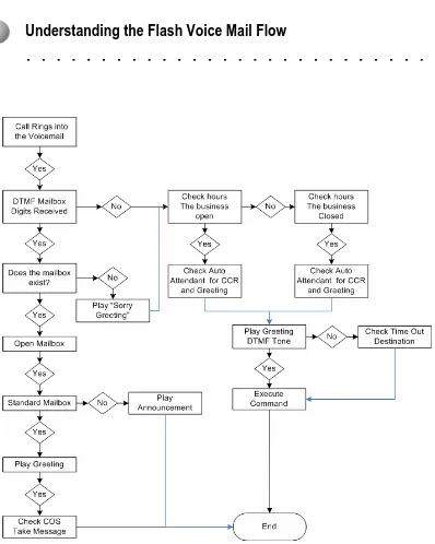
Understanding the Flash Voice Mail Flow
Figure 3 Voice Mail Flow Chart
Setup
5
Understanding the “Flow” of the voice mail system will help when customizing it for
your customers. This section describes the various setup screens that are accessible
from the Programming Main Menu (Figure).
If a field entry has not been entered after 10 minutes, the system will timeout and will return to the Enter Password Screen.
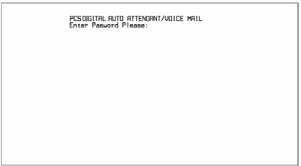
Suite 64 Flash Voice Mail System Startup
The Enter Password Screen shown in figure 4, is the first screen displayed when the
programming terminal is connected and the system is powered on. If the system is
already powered ON when connecting the terminal cable, press the E key and this
screen will appear.
Figure 4 Enter Password Screen
The default password is 0000. Instructions for changing the password are
5
Setup
Enter the password and then press R to access the Programming Main Menu
window. If a password is not valid an error message, “Invalid Password” will be
displayed after password authentication. Re‐enter a password and press R. The
system will allow an infinite number of password entry/validation attempts. The
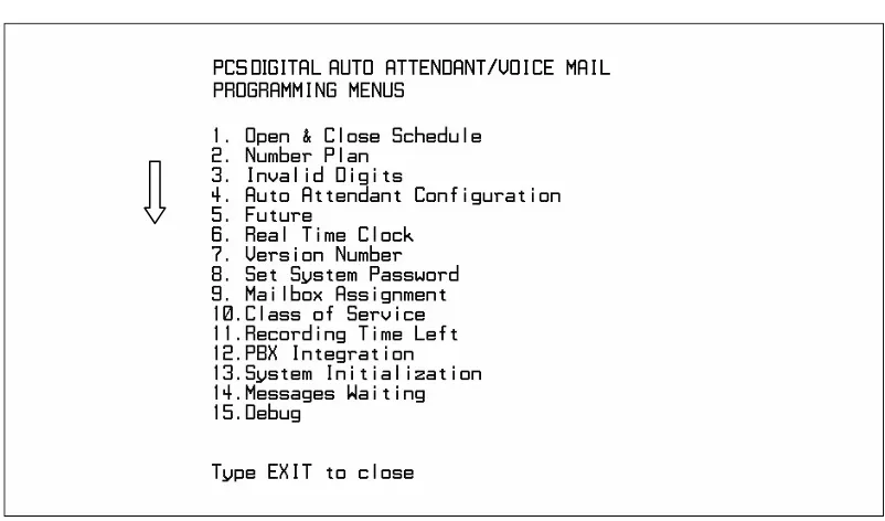
Programming Main Menu shown below in Figure will be displayed.
This menu provides access to the detailed parameter screens needed to program the
Suite 64 Flash Voice Mail System. To navigate to a specific screen either scroll down
to the selection by using t or b or type in the desired menu choice number. Press
the R key to navigate to that screen.
Figure 5
Programming Main Menu
Setup
5
Initialization and PBX Integration
Two steps need to be accomplished initially after Suite 64 Flash Voice Mail System
card has been installed, powered‐up and synchronized.
1. Initialization – This prepares the system for programming, setting up all the
default data tables.
2. If needed, select a new PBX integration (only needed for 2 or 4 digit
Configurations.) Selecting PBX Integration creates the default mailbox numbers
and programs the necessary codes for the selected PBX system. These pre‐
programmed mailbox numbers and PBX codes may be modified as desired for
specific site requirements.
At default the system is set up for three (3) digit extension numbers 401 ‐440. This step is only necessary if a different numbering plan, 2 or 4 digits, is to be used.
Initializing the System
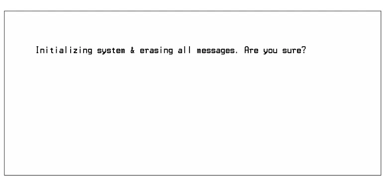
Select 13‐ System Initialization from the Programming Main Menu (Figure 5) and then
press R. A confirmation message appears: “Initializing system & erasing all messages. Are you sure?” This is shown below in Figure 6 indicating that all tables will
be reset.
Figure 6 System Initialization Screen
Press < to initialize the voice mail system. All system values will return to their default
settings. All system mailboxes will be initialized as new with no greetings or names. When
the procedure is finished, the system will automatically restart and ask for your system
password. The default is 0000. There is no way to “Undo” an initialization. Press N to
cancel and exit to the Programming Menu without initializing the voice mail system
5
Setup
PBX System Integration
If needed, Select 12‐PBX Integration from the Programming Main Menu (Figure 5), and
press R. The default PBX Integration Selection Screen shown below in Figure 7
will be displayed.
Figure 7 PBX Integration Selection Screen
1. Select the desired PBX system using the t and b keys and press R. The
active PBX system selection will be indicated at the top of the menu listing.
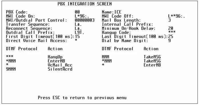
2. Press R again and the PBX Integration Setup Screen as shown below in
Figure 8 will be displayed to view or modify the default values.
Figure 8 PBX Integration Screen
Setup
5
Menu Option 1 - Open & Close Schedule
Select 1‐Open and Close Schedule from the Programming Main Menu Screen (Figure) and
the Open and Close Schedule Screen shown below in Figure will be displayed. This
controls when the Suite 64 Flash Voice Mail System determines a DAY or NIGHT
mode. There are separate greetings available for each mode. Enter the desired time
schedule for each day as required and press R to store each entry. When
complete, press E to return to the Programming Main Menu.
Figure 9 Open and Close Schedule Screen
This Schedule is used to select the CCR Menu, and appropriate greeting, used to
introduce callers to the company and give them instructions, such as the digits to
press to access certain departments, extensions or mailboxes. In the screen above,
the “weekend” greeting begins playing at 5 p.m. Friday and ends at 9:00 a.m.
Monday morning.
5
Setup
Field Descriptions
Sunday thru Saturday – these field entries specify the Opening and Closing greetings
for each of the days of the week. The values should be entered using the 24 hours
format. For example, 1:00 pm would be entered as 13:00.
Open/Close – the opening greeting plays from the time you specify in this field until
the time specified for closing. The closing greeting plays at all other times until the
next specified opening time. The system will not allow a chronologically illogical
number to be added to the Close field. For example, if the Open value is 9:00AM, the
system will only allow PM values to be added or AM values later than 9:00.
If multiple copmanies are sharing the same PBX, they must have the same day/night settings. In this case, it may be beneficial to use 1 generic greeting.
KSU Control – the KSU control synchronizes the Suite 64 system and the voice mail
so that both units switch from one mode, open or close, the other simultaneously.
(This feature requires software version K24UT”1”.XXX and newer.)
Open and Close Schedule Example
As an example, if the Suite 64 Flash Voice Mail System is programmed for a
fictitious company named Acme, Inc., and the settings shown in Figure are set, this
company’s opening and closing greetings, their standard greetings may sound
something like this:
OPENING GREETING: “Thank you for calling Acme Incorporate; if you know the extension of the person you’d like to reach, please dial it now. For assistance, press zero.”
CLOSED GREETING: “You have reached Acme, Incorporated. Our office hours are 9:00 am to five pm., Monday through Friday. To leave a message for an employee, please dial their extension number now. To leave a message in the General Delivery mailbox, dial zero. Someone will respond to your message the next business day.”
Setup
5
Navigating CCR Menus
Figure 10 Navigating CCR Menus
The Following diagram may resemble a typical company; where CCR 1, is used to
answer calls during both the Open and Closed schedule. Callers may select a digit to
be redirected to sub‐menus for sales and support. Callers may then select between
inside and outside sales.
Menu
Sub-Menu1
Sub-Menu2
Previous
Menu
5
Setup
Menu Option 2 – Number Plan
Select 2‐Number Plan from the Programming Main Menu Screen (Figure) and the
Numbering Plan screen shown below in Figure will be displayed. This controls how
the Voice Mail System processes the digits entered by a caller. It is part of the
Automated Attendant function. There are a total of eight (8) screens available ‐ each
corresponding to a Custom Call Routing (CCR) number from 1 to 8.
Use the 1 and 2 keys to cycle through the CCR box screens.
Figure shows that CCR1 is set up to accept digits, 1, 2, 4, 0, *, # and (T)=time
out. The Digit 1, will send the caller to Greeting 4 – then to CCR4; 0 will send the
caller to the system operator. Digits 2 and 4 are considered the first digit of a
UCD/Hunt group or extension number. To user the Dial by Name feature set the
digit 9 is set to (N), it works as a spell by name directory.
Figure 11 System Numbering Plan Screen
Field Descriptions
First Digit Permission ‐ This field tells the System whether a digit is allowed to dial
in the current CCR menu programming. If a digit marked “N” is dialed, the system
will tell the caller they have dialed an incorrect digit and allow them to dial again.
If the dialed digit is marked Y one of the following actions is performed depending
on the data entered in the columns:
Setup
5
If a field entry is made, the first digit permission will automatically change from “N” to “Y”. Similarly, if values exist in a field and “Y” is changed to “N”, all values on the line will be removed.
Extension ‐This field may contain any valid system telephone extension number as
the destination if this digit is pressed. If this field is filled and the corresponding
digit is pressed, the caller is transferred to the programmed extension.
Greeting ‐ This field contains a greeting number from 1 to 10 that will be played
when this digit is pressed. This is useful for making announcements such as
directions to the Company’s office. When a digit is used for a CCR assignment, this
is the greeting number that will be played as the caller is sent to the programmed
CCR box.
All Greetings are recorded from the System Administrator Mailbox. At default the Administrator mailbox is #00.
CCR Number ‐ This field contains the CCR menu destination from 1 to 5 where to
send the caller when this digit is pressed. This is used to send a caller to a sub‐menu
with additional choices. ( i.e. a Technical Support Department.)
5
Setup
Number Plan Example
There are a total of eight (8) CCR menus which can be programmed in the
Numbering Plan screen. Each CCR menu has thirteen (13) different routing options;
each can transfer a caller to extensions or linking to another CCR menu.
Figure 12 Numbering
Plan Screen Example
In figure 12 – digits 1, 2 and 3 are programmed to go to UCD hunt groups, 230, 231
and 232. A typical company may use this as 1 for Sales, 2 for Support, 3 for Account
Payable.
Another example may use 1, 2 and 3 as extensions 430, 431 and 432. A typical
company may use the single digit 1 to go to extension 430, 2 to go to 431, and 3 to go
to 432. When these digits are dialed, callers can be transferred directly to the
extension or can they can be set up as a “Take Message only” transfer; where callers
are transferred directly into the associated mailbox to leave a message.
The following are programming examples for CCR Menus:
A standard set up may resemble ‐ All callers are answered by CCR 1. Greeting
number 1 is assigned to play for this CCR Menu during the day.
Recorded in the programmed greeting for CCR 1, the caller hears as part of the
greeting: “To reach the Sale Department, press 1, for Support press 2, for Accounts Payable, press 3. ”
Setup
5
Programming the example:
1. Enter system programming via the terminal. Go to selection 2 ‐ Number Plan and
press the R key. The programming screen for CCR 1 will be displayed. (the
CCR menu number is located at the top of the screen)
2. Enter a (Y) next to digit 1 to activate this choice and press R.
3. Enter 2 in the Greeting column for digit 1 and press R.
4. Enter 2 in the CCR column for digit 1 and press R.
5. Press the 1 key to advance the screen to CCR 4.
6. Enter a (Y) next to digit 1 to activate the choice and R.
7. Enter 430 in the extension number field and press R.
8. Enter a (Y) next to digit 2 to activate the choice and press R.
9. Enter 431 in the extension number field and press R.
10. Enter a (Y) next to digit 3 to activate the choice and press R.
11. Enter 432 in the Extension field and press R. (To make this a “Mailbox”
only, and not a direct transfer to an extension, call into the system and change
the transfer option for this mailbox.)
5
Setup
Single Digit Dialing with Automated Attendant Functions
Suite 64 Flash Voice Mail System supports single digit and Automated Attendant
dialing using the same digit(s).
1. Press 1 and select the CCR Menu to be programmed.
2. Enter a (Y) next to digit 1 to activate the choice and R.
3. Enter 430 in the extension number field and press R.
4. Enter a (Y) next to digit 2 to activate the choice and press R.
5. Enter 431 in the extension number field and press R.
6. Enter a (Y) next to digit 3 to activate the choice and press R.
7. Enter 432 in the Extension field and press R.
If the caller presses 1 or 2 and no further digits, the system will send them to the
programmed action for that line ‐ in this case the caller will be transferred to
Extension 430 if the digit 1 is pressed, Extension 431 if the digit 2 is pressed and
Extension 432 if the digit 3 is pressed. If the digit 0 is pressed, the caller is played
the message recorded on greeting 5, then sent to CCR 1. General Delivery Mailbox
When the system is in closed (night) mode, and if a caller does not press a key while
listening to the CCR night greeting, the system will send the caller to the General
Delivery mailbox to leave a message.
The General Delivery Mailbox is the first defined mailbox in the system. Any
messages left while in night mode may be recovered from that mailbox. By default
the general delivery mailbox is 500.
The following programming can be done to change to General Delivery Mailbox
Number:
1. Press 9 from the Main Menu
2. While the cursor is resting on the first line:
Setup
5
example, if you type in 1 315 the number of the first mailbox will be
changed to 315.
In Addition, the first mailbox can be erased, leaving 401 as the general delivery
mailbox.
1. Press 9 from the Mail Menu
2. While the cursor is resting on the first line:
a. Press 4 to delete the mailbox
b. At the prompt; “Deleting Mailbox, are you sure?” Press “Y” to delete, or “N” to
leave the mailbox.
Announcement Only Mailboxes
Announcement only mailboxes are used to play pre‐recorded information to a caller
such as directions to a company location, monthly sales, Mass Schedules, etc., and
then hang up, releasing the call. If this is not an optimal solution for this application,
a system greeting can be used.
In this example, if a caller dialed
6 then the announcement mailbox 801 would play, and if the caller dial 7 then the
announcement mailbox 802 would play.
Creating Announcement Only Mailboxes:
Mailboxes 801 through 816, or 8001 – 8016 in a 4 digit numbering plan, are reserved
as announcement only mailboxes. However, because they do not exist, they must be
created.
1. Enter 9 to access the Mailbox assignment menu.
2. Press 1 to advance to the end of the mailboxes
3. Enter the mailbox number to be added 801 – 816 (8001 – 8016) depending on the
numbering plan.
4. The announcements (greetings) for these mailboxes can be recorded in the