ISSUE 1 STOCK # 200892
Message Center Interface (MCI)
Specifications
NEC America, Inc. reserves the right to change the specifications, functions, or features, at any time, without notice.
NEC America, Inc. has prepared this document for use by its em-ployees and customers. The information contained herein is the property of NEC America, Inc. and shall not be reproduced without prior written approval from NEC America, Inc.
NEAX and Dterm are registered trademarks of NEC Corporation. Copyright 1999
ISSUE 1 JANUARY, 1999
NEAX2400 IMX
Message Center Interface (MCI) Specifications
TABLE OF CONTENTS
Page
LIST OF FIGURES . . . ii
LIST OF TABLES . . . iii
CHAPTER 1 INTRODUCTION . . . 1
CHAPTER 2 MCI FOR IOC . . . 3
1. SPECIFICATIONS . . . 3
1.1 Interface . . . 3
1.2 Text Format. . . 3
2. PROTOCOL AND MESSAGE RESPONSES . . . 4
2.1 PBX → MC . . . 4
2.2 MC → PBX . . . 4
CHAPTER 3 MCI FOR LAN . . . 5
1. SPECIFICATIONS . . . 5
1.1 Timing . . . 5
1.2 Interface . . . 5
1.3 Basic Configuration of Text . . . 6
1.4 Text Format. . . 9
2. PROTOCOL AND MESSAGE RESPONSES . . . 13
2.1 Link Establishment Sequence . . . 13
2.2 Transmission and Reception of Call Information . . . 14
2.3 MWL Control . . . 19
2.4 Monitoring Status Between Client and Server . . . 23
2.5 Link Release Sequence . . . 24
2.6 Connection Sequence for System Changeover . . . 25
CHAPTER 4 MESSAGE FORMAT . . . 27
1. ICS FORMAT . . . 27
2. IMX FORMAT . . . 31
CHAPTER 5 SERVICE CONDITIONS . . . 39
Figure Title Page
Figure 1-1 MCI for UCD Incoming Call . . . 1
Figure 1-2 MCI for Attendant Incoming Call . . . 1
Figure 2-1 Word Framing Example . . . 3
Figure 2-2 Typical Text Format . . . 3
Figure 3-1 PBX and MCI for LAN Interface . . . 6
Figure 3-2 Text Basic Configuration . . . 6
Figure 3-3 Lamp Control Text Configuration . . . 9
Figure 3-4 Call Information Text Configuration . . . 9
Figure 3-5 Server Response Text Configuration . . . 10
Figure 3-6 Client Response Text Configuration . . . 11
Figure 3-7 Status Monitoring Text Configuration . . . 11
Figure 3-8 Link Release Text Configuration . . . 12
Figure 3-9 Link Establishment Sequence . . . 13
Figure 3-10 Transmission and Reception of Call Information Sequence . . . 14
Figure 3-11 Transmission and Reception of Call Information Error Processing Sequence (1) . . . 15
Figure 3-12 Transmission and Reception of Call Information Error Processing Sequence (2) . . . 16
Figure 3-13 Transmission and Reception of Call Information Error Processing Sequence (3) . . . 17
Figure 3-14 Transmission and Reception of Call Information Error Processing Sequence (4) . . . 18
Figure 3-15 MWL Control Processing Sequence . . . 19
Figure 3-16 MWL Control Error Processing Sequence (1) . . . 20
Figure 3-17 MWL Control Error Processing Sequence (2) . . . 21
Figure 3-18 MWL Control Error Processing Sequence (3) . . . 22
Figure 3-19 Monitoring Status Between Client and Server Processing Sequence . . . 23
Figure 3-20 Link Release Sequence . . . 24
Table Title Page
Table 4-1 Call Type Codes for Attendant Incoming Calls . . . 29
Table 4-2 Call Type Codes for UCD Incoming Calls . . . . 29
Table 4-3 Message Text Station Number Explanation . . . 30
Table 4-4 PBX → MC Data Type Explanation . . . 31
Table 4-5 Call Type Codes for Attendant Incoming Calls . . . 34
Table 4-6 Call Type Codes for UCD Incoming Calls . . . . 34
Table 4-7 MC → PBX Data Type Explanation . . . 35
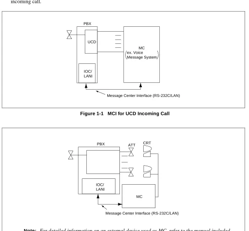
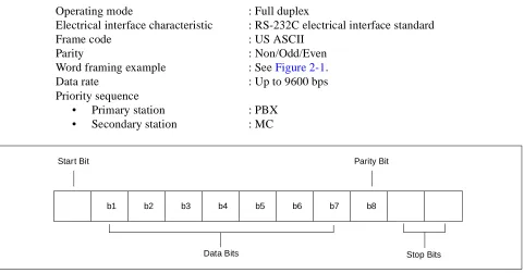
This manual provides the Message Center Interface (MCI) specifications for the NEAX2400 IMX system. When a call terminates to the attendant or a Uniform Call Distribution (UCD) station, the call information is sent via the MCI to the Message Center (MC). Based on the call information from the Private Branch Exchange (PBX), the MC achieves ON/OFF control of the Message Waiting Lamp (MWL) and Message Waiting (MW) indication of the station. Figure 1-1 and Figure 1-2 show the MCI for a UCD incoming call and an attendant incoming call.
Figure 1-1 MCI for UCD Incoming Call
Figure 1-2 MCI for Attendant Incoming Call PBX
IOC/ LANI
UCD
Message Center Interface (RS-232C/LAN) MC
ex. Voice Message System
Note: For detailed information on an external device used as MC, refer to the manual included with the external device.
PBX
IOC/ LANI
MC
1. SPECIFICATIONS 1.1 Interface
This section has information on the signal interface requirements for the MCI for Input/Output Controller (IOC).
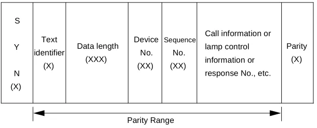
Operating mode : Full duplex
Electrical interface characteristic : RS-232C electrical interface standard
Frame code : US ASCII
Parity : Non/Odd/Even
Word framing example : See Figure 2-1.
Data rate : Up to 9600 bps
Priority sequence
• Primary station : PBX
• Secondary station : MC
Figure 2-1 Word Framing Example 1.2 Text Format
MCI for IOC uses the following text format.
Figure 2-2 Typical Text Format
b1 b2 b3 b4 b5 b6 b7 b8
Data Bits Stop Bits
Parity Bit Start Bit
S T X
S A
U A
E I
E T X Message text
(Refer to CHAPTER 4.)
2. PROTOCOL AND MESSAGE RESPONSES
This section has information on protocol and message responses of MCI for IOC. For detailed information on each message, refer to CHAPTER 4.
2.1 PBX → MC
2.2 MC → PBX
(1) When receiving messages controlling one station, the following text format applies.
(2) When receiving queue is full, the PBX sends Call Type 39. This requests MC to stop transmission. When the PBX has processed all MWL requests in full queue, the PBX sends Call Type 66. This requests MC to start sending MWL data.
receive receive send send PBX MC S T X E T X S A U A S T X E T X S A U A t Note Data Data
Note: The interval between communications is the Guard Timing (GT) value programmed in ASYD (SYS1, Index 28, Bits 0-4).
receive send receive send PBX MC S T X E T X S A U A S T X E T X S A U A 350 ms or longer
STA1 STA1
receive receive receive
receive
send send
send send
PBX
MC message message message
Call Type 39
(Stop Sending MW Control Data) wait receive send send receive PBX MC
Call Type 66
1. SPECIFICATIONS 1.1 Timing
Timing to Establish a Link : A link is connected when an MC connect request is received.
Timing to Output Call Information : When a call terminates to the attendant or a UCD group station, the call information is sent via the MCI to the MC.
Timing to Receive MWL Information : When Message Waiting Lamp (MWL) information is received, the MWL of the station served by the PBX is caused to be ON/ OFF.
Timing to Release the Link : The MC for Local Area Network (LAN), which is a client of the PBX, discards the socket and performs processing to re-lease the link when it does not receive a “Call Information Text” or “Server Response Text” in a given time interval from the server. When the PBX or the server does not receive a “Lamp Control Text”, “Client Response Text”, or “Status Mon-itoring Text” in a given time interval from the client, it performs NG processing + sends a “Connection Disconnect Text” and then discards the socket and performs processing to release the link.
1.2 Interface
This section has information on the interface requirements for the PBX and the external device (MC for LAN). Figure 3-1 shows the PBX and the MCI for LAN interface.
Protocol : Stream type socket (TCP) protocol
Physical condition : Ethernet
Software conditions
• PBX : Socket interface (capability provided to deal with WinSock) • External device : Shall use the WinSock, UNIX socket and other libraries.
Port No. : 60020 (defined at PBX side)
Codes to be used
• Transmission code : ASCII 8 bits without parity • Control codes
SYN : 16H indicates the beginning of a text.
STX : 02H indicates the beginning of an MCI record.
Figure 3-1 PBX and MCI for LAN Interface 1.3 Basic Configuration of Text
Data is transferred between the server and client in the unit of a text.
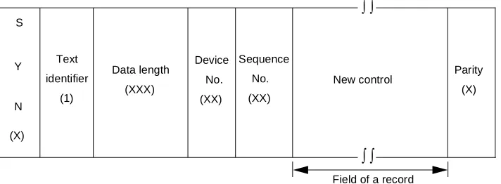
A text, as shown in Figure 3-2, consists of SYN (16H), used as the beginning of a text, a text identifier, data length, device No., sequence No., message and parity (horizontal parity check system).
The result of the exclusive logical sum of the parity range is set as the parity.
(If the result of the exclusive logical sum of the range from the text identifier to the parity is even parity, the check bit is set to “0”. If it is odd parity, the check bit is set to “1”.)
Figure 3-2 Text Basic Configuration
(1) SYN: Text Data Start Position Information
The SYN defines the position where the text data to be sent or received is to start.
Data type : Hexadecimal
Data size : 1 byte
Data : SYN 16H
Application
Socket
TCP/IP
Ethernet Call information/MWL information transfer protocol
PBX
Application
Socket
TCP/IP
Ethernet Call information/MWL information transfer protocol
External Device (MC for LAN)
Call information/MWL information protocol
S
Y
N (X)
Text identifier
(X)
Device No. (XX)
Parity (X)
Sequence
No. (XX)
Call information or lamp control information or response No., etc. Data length
(XXX)
(2) Text Identifier
The text identifier identifies the data to be sent or received.
Data type : Decimal (ASCII code)
Data size : 1 digit
Data range: 0 to 9
0 : Not used
1 : Lamp Control Text (MC for LAN PBX)
The PBX that received the data sends the result of the received data check as a “Server Response Text (text identifier (3))” to the MC for LAN in a predetermined time inter-val.
2 : Call Information Text (PBX MC for LAN)
The MC for LAN that received the data sends the result of the received data check as a “Client Response Text (text identifier (4))” to the PBX in a predetermined time in-terval.
3 : Server Response Text (PBX MC for LAN)
When the PBX receives identifiers (1) or (5), it sends the result of the received data check to the MC for LAN.
4 : Client Response Text (MC for LAN PBX)
When the MC for LAN receives identifier (2), it sends the result of the received data check to the PBX.
5 : Status Monitoring Text (MC for LAN PBX)
When both the MC for LAN and PBX do not send any of the various types of process-ing requests, a status monitorprocess-ing text is sent by the MC for LANs in a predetermined time interval.
When the PBX receives the text, it monitors the status of the client.
6 : Link Release Text (MC for LAN PBX)
A link release request text sent from the client to the server and from the server to the client.
(3) Data Length
The data length indicates the length of data to be sent and received between the server and client.
The number of bytes ranging from the character following the data length to the character preceding to the parity is set in terms of 3 digits.
Data type : Decimal (ASCII code)
Data size : 3 digits
(4) Device No.
The device No. indicates the device No. for the MC for LAN connected to the server.
The MC for LAN sends its own device No. to the server, and the PBX sends the device No. for the MC for LAN, which is the destination of the text.
The device No. to be used is defined at the PBX side.
Data type : Decimal (ASCII code)
Data size : 2 digits
Data range: 0 to 99
(5) Sequence No.
The sequence No. is a serial number for the data to be sent.
It is a number assigned to assure that the transferred data is cleared.
The PBX and server manage independent numbers respectively.
Data type : Decimal (ASCII code)
Data size : 2 digits
Data range: 0 to 99
(6) Parity
The horizontal parity check method is adopted. The calculation range is from the text identifier to the char-acter preceding to the parity. By default, odd parity is used.
The parity check method can be changed in system data.
Data type : Hexadecimal
Data size : 1 byte
1.4 Text Format
(1) Lamp Control Text (MC for LAN PBX)
Figure 3-3 shows text to be sent when a request for control from the MC for LAN is presented. The format in a record is the IMX format of MCI message. It complies with the format of MC PBX message in CHAPTER 4, Section2, IMX FORMAT.
Figure 3-3 Lamp Control Text Configuration
(2) Call Information Text (MC for LAN PBX)
Figure 3-4 shows the call information text to be sent from the PBX to the MC for LAN. The format in a record is the IMX format of MCI message. It complies with the format of PBX MC message in CHAP-TER 4, Section2,IMX FORMAT.
As for text identifier (2), a piece of call information is created when a call terminates to the attendant or a UCD station and when text is sent to the MC for LAN. Therefore, each text contains one record.
Figure 3-4 Call Information Text Configuration S
Y
N
(X)
Text
identifier
(1)
Data length (XXX)
Device
No.
(XX)
Sequence
No.
(XX)
New control Parity (X)
Field of a record
∫ ∫
∫ ∫
S
Y
N
(X)
Text
identifier
(2)
Data length
(XXX)
Device
No.
(XX)
Sequence
No.
(XX)
Call information Parity (X)
Field of a record
∫ ∫
(3) Server Response Text (MC for LAN PBX)
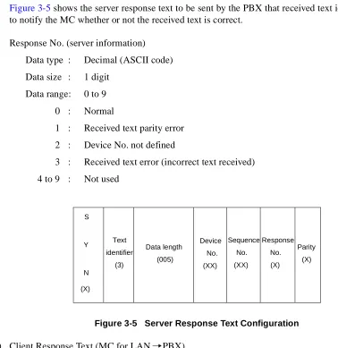
Figure 3-5 shows the server response text to be sent by the PBX that received text identifiers (1) and (5) to notify the MC whether or not the received text is correct.
Response No. (server information)
Data type : Decimal (ASCII code)
Data size : 1 digit
Data range: 0 to 9
0 : Normal
1 : Received text parity error
2 : Device No. not defined
3 : Received text error (incorrect text received)
4 to 9 : Not used
Figure 3-5 Server Response Text Configuration
(4) Client Response Text (MC for LAN PBX)
Figure 3-6 shows the client response text to be sent by the MC for LAN that received text identifier (2) to notify the PBX whether or not the received text is correct.
Response No. (client side information)
Data type : Decimal (ASCII code)
Data size : 1 digit
Data range: 0 to 9
0 : Normal
1 : Received text parity error
2 : Not used
3 : Received text error (incorrect text received)
4 to 9 : Not used
S
Y
N
(X)
Text
identifier
(3)
Data length (005)
Device
No.
(XX)
Sequence
No.
(XX)
Parity (X) Response
No.
Figure 3-6 Client Response Text Configuration
(5) Status Monitoring Text (MC for LAN PBX)
The text shown in Figure 3-7 is defined for use in monitoring the server status from the client and the client status from the server. In response to the text, the server sends a “Server Response Text (3)” to the client.
Client device information
Data type : Decimal (ASCII code)
Data size : 2 digits
Data range: 0 to 99
Data type
00 : Normal
01 to 99 : To be defined at MC side
Figure 3-7 Status Monitoring Text Configuration S
Y
N
(X)
Text
identifier
(4)
Data length
(005)
Device
No.
(XX)
Sequence
No.
(XX)
Parity
(X) Response
No.
(X)
S
Y
N
(X)
Text
identifier
(5)
Data length
(006)
Device
No.
(XX)
Sequence
No.
(XX)
Parity
(X) Client device
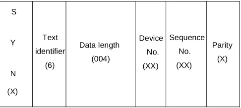
(6) Link Release Text (MC for LAN PBX)
Figure 3-8 shows a link release request to be sent from the client to the server and from the server to the client. Processing is performed to release the link immediately after the text is received.
Figure 3-8 Link Release Text Configuration S
Y
N
(X)
Text
identifier
(6)
Data length
(004)
Device
No.
(XX)
Sequence
No.
(XX)
Parity
2. PROTOCOL AND MESSAGE RESPONSES 2.1 Link Establishment Sequence
Figure 3-9 shows the sequence used when the client requests the server to establish a link.
Figure 3-9 Link Establishment Sequence
Note: The client sends a status monitoring text immediately after a link is established.
Client (MC for LAN) Server (PBX)
Connection request (CONNECT)
Connection accepted (ACCEPT)
Status monitoring
Server response text
System equipment OK
Note 5
00
Text identifier
Response No.
3
*
Text identifier
2.2 Transmission and Reception of Call Information
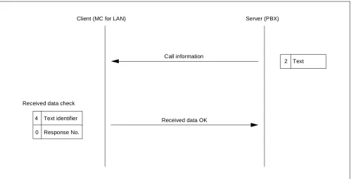
(1) Normal Processing Sequence for Transmission and Reception of Call Information
Figure 3-10 shows the normal sequence used when the server sends call information to the client.
Figure 3-10 Transmission and Reception of Call Information Sequence
Client (MC for LAN) Server (PBX)
Call information
2 Text
Received data OK Received data check
4
0
Text identifier
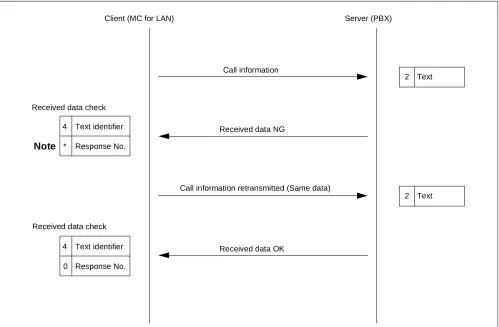
(2) Error Processing Sequence (1) for Transmission and Reception of Call Information
Figure 3-11 shows the error processing sequence used when the server sends call information to the client.
Figure 3-11 Transmission and Reception of Call Information Error Processing Sequence (1) Note: The * value varies with an error in the received data. (Refer to CHAPTER3, Section1.4,
(4) Client Response Text.)
Client (MC for LAN) Server (PBX)
Call information
Received data NG
Call information retransmitted (Same data)
Received data OK
2 Text
2 Text Received data check
Note
Received data check
4
0
Text identifier
Response No. 4
*
Text identifier
(3) Error Processing Sequence (2) for Transmission and Reception of Call Information
Figure 3-12 shows the error processing sequence used when the server sends call information to the client.
Figure 3-12 Transmission and Reception of Call Information Error Processing Sequence (2) Note 1: The * value varies with an error in the received data. (Refer to CHAPTER 3, Section 1.4,
(4) Client Response Text.)
Note 2: The maximum number of times the same data is sent is 6. When the text checks NG six consecutive times, the socket is discarded and the link released.
Client (MC for LAN) Server (PBX)
Call information
Received data NG
Call information retransmitted (Same data)
Received data NG
Call information retransmitted (Same data)
Received data NG
Link release text 4
*
Text identifier
Response No.
2 Text
2 Text
2 Text
6 Text Received data check
Note 1
4
*
Text identifier
Response No. Received data check
4
*
Text identifier
Response No. Received data check
First time
Second time
Sixth time
Note 2
Socket discarded Link released
(Client response text is not sent.)
Socket discarded Link released
(4) Error Processing Sequence (3) for Transmission and Reception of Call Information
Figure 3-13 shows the processing sequence used when the server sends call information to the client and does not receive any client response text.
Figure 3-13 Transmission and Reception of Call Information Error Processing Sequence (3) Note 1: The * value varies with an error in the received data. (Refer to CHAPTER 3, Section 1.4,
(4) Client Response Text.)
Note 2: The maximum number of times the same data is sent is limited to 6. When the text checks NG six consecutive times, the socket is discarded and the link released.
Client (MC for LAN) Server (PBX)
Call information
Client response text
Call information retransmitted (Same data)
Client response text
Call information retransmitted (Same data)
Client response text
Link release text 4
*
Text identifier
Response No.
2 Text
2 Text
2 Text
6 Text Received data check
Note 1
Received data check
Received data check
First time
No text received
Note 2
Socket discarded Link released
(Client response text is not sent.)
Socket discarded Link released
T1 timer
Second time
No text received
T1 timer
Sixth time
No text received
T1 timer 4
*
Text identifier
Response No.
4
*
Text identifier
Response No.
∫ ∫ ∫ ∫
(5) Error Processing Sequence (4) for Transmission and Reception of Call Information
Figure 3-14 shows the sequence used when the server sends call information to the client and does not receive any client response text or detects an error in the data received by the client; the server then releas-es the link connected to the smaller numbered MC for LAN and sends call information to the other MC for LAN.
Figure 3-14 Transmission and Reception of Call Information Error Processing Sequence (4)
Client (MC for LAN) Server (PBX)
Call information retransmitted (Same data)
Client response text
Link release text
Call information retransmitted (Same data)
Client response text
2 Text
6 Text
2 Text Received data check
Received data check
Sixth time
No text received
Socket discarded Link released
(Client Response Text is not sent.)
Socket discarded Link released
T1 timer
Sixth time
No text received
T1 timer Transmission to the other MC for external LANs started
∫ ∫ ∫ ∫
∫ ∫ ∫ ∫
4
*
Text identifier
Response No.
4
*
Text identifier
2.3 MWL Control
(1) Normal Processing Sequence for Control of MWL
Figure 3-15 shows the normal processing sequence used when the client requests the server to control MWL.
Figure 3-15 MWL Control Processing Sequence
Client (MC for LAN) Server (PBX)
Lamp control request 1 Text
Received data OK
Received data check
Lamp control 3
0
Text identifier
(2) Error Processing Sequence (1) for Control of MWL
Figure 3-16 shows the processing sequence used when the client requests the server to control MWL and detects an error in the received data.
Figure 3-16 MWL Control Error Processing Sequence (1)
Note: The * value varies with an error in the received data. (Refer to CHAPTER 3, Section 1.4, (3) Server Response Text.)
Client (MC for LAN) Server (PBX)
Lamp control request
Received data NG
Lamp control request (Same text)
Received data OK 1 Text
1 Text
Note
Lamp control 3
0
Text identifier
Response No. 3
*
Text identifier
(3) Error Processing Sequence (2) for Control of MWL
Figure 3-17 shows the processing sequence used when the client requests the server to control MWL and detects an error in the received data.
Figure 3-17 MWL Control Error Processing Sequence (2) Client (MC for LAN) Server (PBX)
Lamp control request
Received data NG
Lamp control request retransmitted (Same data)
Received data NG
Lamp control request retransmitted (Same data)
Received data NG
Link release text 1 Text
1 Text
1 Text
6 Text
Note 1 First time
Second time
Sixth time
Socket discarded Link released
Socket discarded Link released
(Client Response Text is not sent.)
Note 2
∫ ∫ ∫ ∫
3
*
Text identifier
Response No.
3
*
Text identifier
Response No.
3
*
Text identifier
Response No.
Note 1: The * value varies with an error in the received data. (Refer to CHAPTER 3, Section 1.4, (3) Server Response Text.)
(4) Error Processing Sequence (3) for Control of MWL
Error processing sequence to be followed when the client requests the server to control MWL and does not receive any server response text.
Figure 3-18 MWL Control Error Processing Sequence (3) Client (MC for LAN) Server (PBX)
Lamp control request
Server response text
Lamp control request retransmitted (Same data)
Server response text
Lamp control request retransmitted (Same data)
Server response text
Link release text 1 Text
1 Text
1 Text
6 Text First time
No text received
Note 2
Socket discarded Link released
(Client Response Text is not sent.)
Socket discarded Link released T2 timer
Second
No text received T2 timer
Sixth time
No text received T2 timer
3
*
Text identifier
Response No.
3
*
Text identifier
Response No.
3
*
Text identifier
Response No. Note 1
∫ ∫ ∫ ∫
Note 1: The * value varies with an error in the received data. (Refer to CHAPTER 3, Section 1.4, (3) Server Response Text.)
Note 2: The maximum number of times the same data is sent is limited to 6. When the text checks NG six consecutive times, the socket is discarded and the link released.
2.4 Monitoring Status Between Client and Server
Figure 3-19 shows the processing sequence for monitoring status between client and server.
Figure 3-19 Monitoring Status Between Client and Server Processing Sequence Client (MC for LAN) Server (PBX)
Status monitoring
Server response text
Status monitoring
Status monitoring Server response text Note 3
Note 3
Note 2
Note 1
T3 timer
3
*
Text identifier
Response No.
3
*
Text identifier
Response No. 5
00
Text identifier
Client status
5
00
Text identifier
Client status
5
00
Text identifier
Client status
Note 1: When six consecutively received texts assigned text identifier (6) check NG, the server sends text identifier (6) and then discards the socket and releases the link.
Note 2: The * value varies with an error in the received data. (Refer to CHAPTER 3, Section 1.4, (3) Server Response Text.)
Note 3: The time from when a text assigned text identifier (5) is sent to when another assigned the same text identifier is sent depends on the timer value of T3 timer.
2.5 Link Release Sequence
Figure 3-20 shows the link release sequence used in response to a request from the client.
Figure 3-20 Link Release Sequence
Client (MC for LAN) Server (PBX)
Link release request
Server response text Note 1
Note 2
Note 1: The device number conforms to the device number assigned to the MC for LAN.
Note 2: When six consecutively received texts assigned text identifier (6) check NG, the server discards the socket and releases the link.
6
**
Text identifier
Device No.
3
0
Text identifier
2.6 Connection Sequence for System Changeover
Figure 3-21 shows the link release sequence used in response to a request from the client.
Figure 3-21 System Changeover Connection Sequence
Client (MC for LAN) Server (PBX)
Data transmitted
Data transmitted
Data transmitted
Connection request (CONNECT)
Connection accepted (ACCEPT) ** Text
** Text
** Text Note 1
Note 2
One side of system changed
over to the other
System equipment OK ARP cache cleared
∫ ∫ ∫ ∫
Note 1: Data from client
1. ICS FORMAT
(1) PBX MC Message
• When ASYD, Index 400, bit 2 is 0 (Calling number information is not sent)
• When ASYD, Index 400, bit 2 is 1 (Calling number information is sent)
B Y T E 0 1 0 2 0 3 0 4 S T X S A 0 U A ! E I J E T X 0 5 0 6 0 7 0 8 0 9 1 0 1 1 1 2 1 3 1 4 1 5 1 6 1 7 1 8 1 9 2 0 2 1 2 2 2 3 2 4 2 5 2 6 2 7 2 8 2 9 3 0 3 1 3 2 3 3 3 4 3 5 3 6
Source of Information Calling Party Called Party D
A T
A Note 1 Note 1 Note 1
Call TypeNote 3
Loop Number Note 2
( ( ( ( ( ( 0 1 0 2 0 3 0 4 S T X E T X S A 0 U A ! E I J 0 5 0 6 0 7 0 8 0 9 1 0 1 1 1 2 1 3 1 4 1 5 1 6 1 7 1 8 1 9 2 0 2 1 2 2 2 3 2 4 2 5 2 6 2 7 2 8 2 9 3 0 3 1 3 2 3 3 3 4 3 5 3 6 3 7 3 8 3 9 7 7 7 8 7 9
Source of Information Calling Party Called Party
B Y T E B Y T E 3 6 3 7 3 8 3 9 A 4 0 4 1 4 2 4 3 4 4 4 5 4 6 4 7 4 8 4 9 5 0 5 1 5 2 5 3 5 4 5 5 5 6 5 7 5 8 5 9 6 0 6 1 6 2 6 3 6 4 6 5 6 6 6 7 6 8 6 9 7 0 7 1 7 2 7 3 7 4 7 5 7 6 7 7 7 8 7 9 Extended Calling Party
0 : Calling number not provided 1 : Calling number provided
8 0
8 0
Z Calling Party Information
End of Extended Format Identifier D A T A D A T A Note 1
Note 1 Note 1 Note 1
Call Type Note 3
Loop Number Note 2
Note 1:
• When the destination is a station
• When the destination is the attendant
• When the destination is a trunk
• When the destination is a trunk (a calling number provided)
0
Tenant Number I
D blank
Station Number
1
Tenant Number I
D Attendant Number
blank
2
Route Number Tenant Number I
D Trunk Number
3
Route Number Tenant Number I
Note 2: This information is valid when Source of Information is the attendant. Note 3: Table 4-1 and Table 4-2 identify the call types.
Table 4-1 Call Type Codes for Attendant Incoming Calls CALL TYPE
CODE CALL TYPE SOURCE
CALLING PARTY
CALLED PARTY
10 Automatic Recall ATT STA/TRK STA
11 Attendant Camp-On ATT TRK STA
12 Call Forwarding-Don’t Answer ATT STA/TRK STA
13 Call Forwarding-Busy Line ATT STA/TRK STA
14 Call Forwarding-All Calls ATT STA/TRK STA
15 Operator Call ATT STA
--16 House Phone ATT STA
--17 Off-Hook Alarm ATT STA
--20 Intercept Call to the Attendant ATT STA/TRK
--21 Call Transfer-Attendant ATT STA/TRK STA/TRK
22 Recall from a Series Call ATT TRK STA
23 Series Call Re-entry ATT TRK STA
24 Tandem Transferring/Hold Entry ATT TRK TRK
26 Inter-Position Transfer ATT STA/TRK ATT
27 CAS Incoming Call ATT TRK
--30 LDN Call ATT TRK
--36 Call Returned from Hold ATT STA/TRK
--39 Stop Sending MW Control Data -- --
--66 Start Sending MW Control Data -- --
--Table 4-2 Call Type Codes for UCD Incoming Calls CALL TYPE
CODE CALL TYPE SOURCE
CALLING PARTY
CALLED PARTY
40 Call Forwarding-Don’t Answer STA STA/TRK STA
41 Call Forwarding-Busy Line STA STA/TRK STA
42 Call Forwarding-All Calls STA STA/TRK STA
43 STA/TRK STA STA/TRK UCD-Pilot
44 STA/TRK via ATT STA STA/TRK ATT
45 STA/TRK Transferred to UCD Pilot Station
(2) MC PBX Message • When Entry Index is A
• When Entry Index is B
Note 1: This information has the following meanings:
0: All MWL Off
1: MWL On for MC
2: MWL On for VMS
5: MWL Off for MC
6: MWL Off for VMS
Note 2: Table 4-3 explains the meaning of STA1 and STA2. The number of digits in the station number and the tenant number of these stations must be the same.
Note 3: If the tenant number in the MWL control data is not used, default value of tenant number is one. Table 4-3 Message Text Station Number Explanation
STA1 STA2 MEANING
Station data blank Station 1 MWL On/Off
Station data Station data MWL is set/cancelled for all stations between Station 1 and Station 2.
blank blank MWL is set/cancelled for all stations in system.
2. IMX FORMAT
(1) PBX MC Message
(a) Summary of format
(b) Data type list (see Table 4-4)
Table 4-4 PBX → MC Data Type Explanation
Data Type Description Data Length
00 Not used —
01 Destination information (Source of information) 16 to 34
02 Loop number/Call type 04
03 Calling party information 16 to 34
04 Called party information 16 to 34
05 Extended calling party information 16 to 34
06 Calling number information 01 to 33
07 to 99 Not used —
Data field S
Y
X
0 ! J Data type
E
T
X Data
length
Data type
Data
length Data field
∫ ∫
∫ ∫
∫ ∫
(c) Details of format
Source of Information Call
type
Destination information Note 1 Note 2
18
to
34
01
to
33 Extended Calling Party
05 06
Extended calling party information Note 1 Calling number information 18
to
34
18
to
34
Calling Party Called Party 03 04
Calling party information Note 1 Called party information Note 1
S
T
X
0 ! J 01 18
to
34
02 04 Loop
No.
Identifier
0 : Calling number not provided
1 : Calling number provided
E
T
X
∫ ∫
∫ ∫
∫ ∫
∫ ∫
∫ ∫
∫ ∫
∫ ∫
∫ ∫
∫ ∫
Note 1:
• When the destination is a station
• When the destination is the attendant
• When the destination is a trunk
• When the destination is a trunk (a calling number provided)
Note 2: When the call type is 39 (wait request) or 66 (wait cancel), the information of data type (02) only is transmitted. Table 4-5 and Table 4-6 show the call types.
0 FPC (3 digits) Tenant Number (3 digits) Station number (8 digits) User group number (3 digits) Telephone number
(16 digits maximum)
Table 4-5 Call Type Codes for Attendant Incoming Calls CALL TYPE
CODE CALL TYPE SOURCE
CALLING PARTY
CALLED PARTY
10 Automatic Recall ATT STA/TRK STA
11 Attendant Camp-On ATT TRK STA
12 Call Forwarding-Don’t Answer ATT STA/TRK STA
13 Call Forwarding-Busy Line ATT STA/TRK STA
14 Call Forwarding-All Calls ATT STA/TRK STA
15 Operator Call ATT STA
--16 House Phone ATT STA
--17 Off-Hook Alarm ATT STA
--20 Intercept Call to the Attendant ATT STA/TRK
--21 Call Transfer-Attendant ATT STA/TRK STA/TRK
22 Recall from a Series Call ATT TRK STA
23 Series Call Re-entry ATT TRK STA
24 Tandem Transferring/Hold Entry ATT TRK TRK
26 Inter-Position Transfer ATT STA/TRK ATT
27 CAS Incoming Call ATT TRK
--30 LDN Call ATT TRK
--36 Call Returned from Hold ATT STA/TRK
--39 Stop Sending MW Control Data -- --
--66 Start Sending MW Control Data -- --
--Table 4-6 Call Type Codes for UCD Incoming Calls
CALL TYPE
CODE CALL TYPE
SOURCE OF INFORMATION
CALLING PARTY
CALLED PARTY
40 Call Forwarding-Don’t Answer STA STA/TRK STA
41 Call Forwarding-Busy Line STA STA/TRK STA
42 Call Forwarding-All Calls STA STA/TRK STA
43 STA/TRK STA STA/TRK UCD-Pilot
44 STA/TRK via ATT STA STA/TRK ATT
45 STA/TRK Transferred to UCD Pilot Station
(2) MC PBX Message
(a) Summary of format
(b) Data type list (see Table 4-7)
Table 4-7 MC → PBX Data Type Explanation
Data Type Description Data Length
00 Not used —
01 ON/OFF 01
02 Station No. (STA1) 01 to 16
03 Station No. (STA2) 01 to 16
04 Tenant number/user group number 06
05 to 99 Not used —
Data field S
T
X 0 !
A
/
B Data type
E
T
X Data
length
Data type
Data
length Data field
∫ ∫
∫ ∫
∫ ∫
(c) Details of format
• When Entry Index is A
• When Entry Index is B
Station number/
(16 digits max.)
Station number 1 (STA1)
Note 2
Station number 2 (STA2)
Note 2
S
T
X
0 ! A 01
01 to 16 01 02 01 to 16 03 E T X ON/OFF Note 1 telephone number Station number/
(16 digits max.) telephone number ∫ ∫ ∫ ∫ ∫ ∫ ∫ ∫ Station number/
(16 digits max.)
Station number 1 (STA1)
Note 2
Station number 2 (STA2)
Note 2
S
T
X
0 ! B 01
01 to 16 01 02 01 to 16 03 E T X ON/OFF Note 1 04 Tenant Number (3 digits) User group number (3 digits) 06 E T X telephone number Station number/
(16 digits max.) telephone number ∫ ∫
∫ ∫
∫ ∫
Note 1: This information has the following meanings:
0: All MWL Off
1: MWL On for MC
2: MWL On for VMS
5: MWL Off for MC
6: MWL Off for VMS
Note 2: Table 4-8 explains the meaning of STA1 and STA2. The number of digits in the station number and the tenant number of these stations must be the same.
Note 3: If the tenant number in the MWL control data is not used, default value of tenant number is one. Table 4-8 MC → PBX Data Type Explanation
STA1 STA2 MEANING
Station data blank Station 1 MWL On/Off
Station data Station data MWL is set/cancelled for all stations between Station 1 and Station 2.
(1) A maximum of 2 ports can be used for MCI. When 2 ports are used for MCI, note the following conditions.
• When both ports are operating normally
Transmission: Messages are transmitted from the smaller-numbered port.
Reception: Messages are received from both ports.
• When one of the ports is faulty
Transmission: Messages are transmitted from the port operating normally.
Reception: Messages are received from the port operating normally.
(2) When the communication line between the MCI and the MC is closed, no display appears on the attendant’s CRT.
(3) If the data received from the MC contains text errors or parity errors, the PBX disregards all proceeding data until an STX message is transmitted to indicate another MWL request.
(4) The following list provides service conditions for MCI used in a CCIS network. In the explanation, the fol-lowing words are used:
MC node: The node to which the MC is connected.
Remote node: Nodes in a CCIS network except MC node.
(a) Only one MC can be connected in a CCIS network.
(b) When a call terminates from a remote node to the attendant or a UCD station in the MC node, the route number and trunk number used in the MC node displays as the Calling Party information.
(c) The MC node can control MWLs of all the stations in a maximum of 32 nodes.
(5) The formats of messages to be transferred to and from the IOC can be changed by system data.
(6) LAN interface and IOC interface cannot be concurrently used for MCI.
(7) The following list provides service conditions for MCI for LAN:
(a) The socket interface shall be used for transfer of data to and from the MC connected to LAN.
(b) After the link is released, it shall always be the client that presents a link establishment request.
STEP 1: ASYD - System Data 1, Index 28, Bits 0-4 Assign a Miscellaneous Timer Counter (MTC) used to calculate the message-sending Guard Timer for Message Center. If not required, assign data “0” to these bits.
System Data 1, Index 28, Bit 5 Is Message Waiting Lamp setting from the Message Center to be used? 0/1: No/Yes.
System Data 1, Index 29, Bits 1-7 Assign which I/O port will act as the Message Center Interface (a maximum of 2 ports).
System Data 1, Index 60, Bit 3 UCD Queuing. 0/1: Required/Not Required. Assign this data as “0” (Required).
System Data 1, Index 70, Bit 0 Called Number Display on the console for DID and TIE Line calls must be enabled. Assign Bit 0 as data “1” when System Data 2, Index 6, Bit 7 is also enabled.
System Data 1, Index 78, Bit 0 CALLING NUMBER DISPLAY - Dterm [C-24D] must be en-abled. Assign Bit 0 as data “1”.
System Data 1, Index 78, Bit 1 CALLING STATION STATUS DISPLAY - Dterm [C-22D] must be enabled. Assign Bit 1 as data “1”.
System Data 1, Index 400, Bit 2 0/1: Calling number information is Not sent/sent to MCI.
System Data 2, Index 6, Bit 0 Is MCI service with UCD groups to be enabled? 0/1:No/Yes.
System Data 2, Index 7, Bit 1 Is MCI service for calls via the Attendant Console to be en-abled? 0/1: No/Yes.
STEP 2: AIOC - Assign the function and attribute data of the IOC ports. Note that this data assignment is required for the MCI for IOC. Skip this step when using MCI for LAN.
STEP 3: ASYDL - System Data 1, Index 529, Bits 0 and 1Parity check method for SMDR/MCI with LAN interface.
b1-b0 00 = No parity 01 = Odd parity 10 = Even parity
System Data 1, Index 641, Bit 1 Designate output numbers for MCI IMX format.
0/1: Station Number/Telephone Number. Assign this data to the node connected to MC.
System Data 1, Index 832 Assign the Fusion Point Code (FPC) of the node connected to MC. Assign this data to all nodes.
System Data 1, Index 833, Bit 0 Interface type for MCI. 0/1: IOC/LAN interface.
System Data 1, Index 833, Bit 1 Text format for MCI. 0/1: ICS/IMX format
System Data 1, Index 834, Bit 0 0/1: MC0 for LAN is Not mounted/Mounted.
STEP 4: AUCD - Whether UCD incoming call information is to be sent to a Message Center Interface or not can be specified on a UCD group basis using the following parameter:
MCI: 0/1 (Not to be sent/To be sent to MCI)
STEP 5: ARPC - In the case of CCIS network, assign Remote Point Code (RPC) of each remote node. CSN (Centralized Service Number): 1 (Message Center)