Improved Grid Tie Inverter for Connecting
Solar Power Generation Unit to the Main
Power Supply
Unni M.R1, Akhilesh K2, Arjun R3, Arjun P4, Adharsh V5
Associate Professor, Dept. of EEE, Nehru College of Engineering and Research Centre, Thrissur, Kerala, India1
UG Students, Dept. of EEE, Nehru College of Engineering and Research Centre, Thissur, Kerala, India2,3,4,5
ABSTRACT: Micro solar power systems are designed for the generation of electrical power. They are generally independent of large centralized electric grids and are used in remote areas. By building grid tie inverter the house hold solar power generation systems are connected to the centralized grid system. There is a need to design a low cost single phase power inverter that can be used with small amount of power generation capacity, possibly capable by using small scale solar power generation systems who wish to supply the excess power generated to the electric grid. Operating a renewable energy system in parallel with an electric grid requires special grid interactive or Grid Tie inverter. The power processing circuits of a GTI are similar to that of a conventional portable DC-AC Converter that operates as a stand-alone device. The main differences are in their control algorithm and safety features. A GTI basically takes a variable voltage from a DC source, such as solar panel inverts it to AC synchronized with the mains. It can provide power to our loads and feed an excess of the electricity into the grid. Depending on power and voltage levels, GTIs circuits normally have from one to three stages. The project is designed to construct a 200W normal AC Output power and a 250W maximum AC Output power Grid Tie Inverter. The proposed GTI has Over Current Protection, anti islanding and Reverse Polarity Protection
.
KEYWORDS: Grid Tie Inverter, Over Current Protection, Reverse Polarity Protection.
I.INTRODUCTION
II.SYSTEM MODEL AND ASSUMPTIONS
The block diagram is shown in fig 2.1 consisting of solar panel, GTI, manual relays, house hold supply and electric grid.
Fig 2.1: Block Diagram
Solar panel is the device used to convert solar energy into electrical energy. Solar panel is connected to the GTI and is basic input block of the improved GTI for connecting the solar panel to the main power supply. The size of the panel depends upon the input power required for the operation of the GTI. Solar panel is collection of solar cells. Although each solar cell provides relatively small amount of power, many solar cells spread over a large area provides enough solar power. Normal Household supply is rated to 230V, single phase, 50Hz AC. This supply is used to operate the household equipment. Hence the household supply at the specified range should be obtained from the existing electric grid. Relays are used to turn ON and OFF the GTI system. It can also be used to provide isolation of the two different sources present in the system. In case of maintenance, we can make use of manual relays to turn OFF the connection between existing Grid and GTI or Electric Grid and house hold supply. Grid Tie Inverter is a power inverter that converts DC to AC with an ability to synchronize to interface with the utility line. Its application are converting DC source such as solar panels or small wind turbines into AC for tying with the grid. Operating a renewable energy system in parallel with an electric grid requires special grid interactive or GTI. The power processing circuits of a GTI are similar to that of a conventional portable DC-AC converter that operates as a stand-alone device. The main differences are in their control algorithm and safety features. A GTI basically takes a variable voltage from a DC source, such as solar panel inverts it to AC synchronized with the mains. It can provide power to our loads and feed an excess of the electricity into the grid.
III. SYSTEM DESCRIPTION
The system consists of a microcontroller circuit gate driver, inverter circuit; step up transformer and a filter. Here the step up transformer is designed with respect to the required specification. The SPWM is used instead of maintaining the width of all pulses the same as in the case of multiple-pulse modulation, the width of each pulse is varied in proportion to the amplitude of a sine wave evaluated at the center of the same pulse. This helps to reduce distortion factor and the lowest order harmonics significantly.
The inverter must convert the renewable energy into pure sinusoidal voltage that tracks the grid voltage in amplitude, frequency and phase. For this purpose the inverter must be synchronized with grid. The interconnection of photo-voltaic (PV) system with a grid requires an accurate control of synchronism between converter and grid. The parameters including voltage, phase and frequency of both systems need to be synchronized. There are different types of techniques developed to achieve synchronization but the system used in this study is simple, reliable, and requires small area for installation and need small circuitry. The proposed system is designed for 1.5kW. The parameters of the reference system (Grid) and photo-voltaic system must be equal for efficient synchronization.
Operating Principle
Inverters work by taking the DC power from the source, such as an array of photovoltaic modules and inverting it to AC power so it can be fed into the grid. The inverter must also synchronize its frequency with that of the grid using a local oscillator and limit the voltage to no higher than the grid voltage. Typical modern GTI's have a fixed unity power factor, which means its output voltage and current are perfectly lined up, and its phase angle is within 1 degree of the
RELAYS
GTI
SOLAR PANEL
NORMAL HOUSEHOLD
SUPPLY
AC power grid. The inverter senses the current of the AC grid waveform, and output a voltage to correspond with the grid. Grid-tie inverters are also designed to quickly disconnect from the grid if the utility grid goes down. This is a requirement that ensures that in the event of a blackout, the grid tie inverter will shut down to prevent the energy it produces from harming any line workers who are sent to fix the power grid.
IV. CIRCUIT DIAGRAM
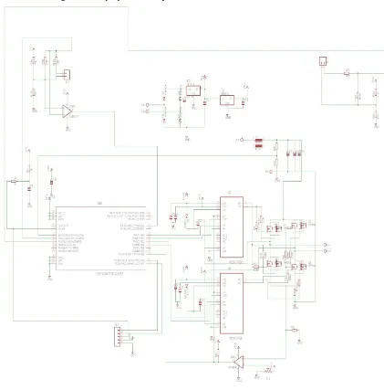
Fig 4.1 shows the circuit diagram of the proposed battery less Grid Tie Inverter.
Fig 4.1: Circuit Diagram of GTI
Circuit Diagram Description for Battery less GTI
use a 100 K resistor. The output of LM393 is given to the third pin of dsPIC30f2010 which is an analog pin (AN1) and it is compared with the square pulse generated in the Microcontroller to find the zero crossing points and then to generate the PWM signal. The generated 5V PWM signal used to produce the synchronized output is given to a gate driver IC IRF2110. The IRF2110 provides the enough threshold voltage for driving the MOSFET P80NF55. The gate driver IC can produce a high and a low output, thus we obtain 2 high and 2 low PWM signals. The 2 high PWM signals will turn ON the 2 MOSFETs say 1 and 3 and the other 2 MOSFETs will be in OFF state. At this condition the 1 and 3 MOSFETs will switch the input signal to get the positive half of the synchronized sine wave. In the next cycle the MOSFETs that were ON turns OFF and the 2 low PWM signals will turn ON the MOSFETs 2 and 4. This will switch the MOSFETs 2 and 4 to obtain the negative half of the synchronized waveform. Thus the MOSFET section can act as inverter. When switching of MOSFETs takes place, the output waveform will be same as that of the samples taken for generating the PWM signal. The drain of the MOSFETs is supplied with 36V obtained from solar panel after eliminating DC variations. The inverter output is given to 36/230V 300VA step-up transformer.
The output of the step-up transformer is given to LC filter in order to remove the harmonics and hence to get a pure sine wave. Here we use a polyester capacitor that can function as a high voltage filter. The normal electrolytic capacitor will burn if a high voltage is applied. Polyester capacitor can used to avoid this problem.
V. SOFTWARE INTEGRATION
Algorithm
STEP 1: SETTING SINEWAVE REFERENCE FOR GENERATING SINEWAVE STEP 2: SETTING TIME PERIOD OF THE SINE WAVE
STEP 3: ALTERING THE DUTY CYCLE OF THE SINE WAVE WITH RESPECT TO REFERENCE SINE WAVE
STEP 4: CHECKING THE ZERO CROSSING MATCH WITH REFERENCE WAVE STEP 5: IF YES, GO TO STEP 7.
STEP 6: IF NO, GO TO STEP 3.
STEP 7: CHECKING THE AMPLITUDE OF THE REFERENCE WAVE. STEP 8: IF YES, GO TO STEP 10.
STEP 9: IF NO, GO TO STEP 3.
STEP 10: GENERATING SINE WAVE (PWM OUTPUT).
VI. RESULT AND DISCUSSION
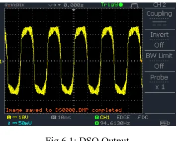
Hardware circuit for our solar power generation system is developed using the specified components. The real system is simulated in the lab by using SIMULINK, and verified the outputs from solar power and grid power.
Fig 6.1: DSO Output
VII.CONCLUSION
As renewable power sources become increasingly prevalent in the near future, power electronics will be able to provide significant advantages in processing power from renewable energy sources using fast response and autonomous control. Vast number of power electronic converters is developed for grid integration of photovoltaic power generation system within a few years and the power extraction from solar cells is getting increased worldwide. In our project we have developed a microcontroller based solar grid-tied inverter. In order to synchronize the output voltage of the inverter with the grid voltage, sinusoidal reference voltage for the microcontroller has been taken from the grid line. The micro- controller generates PWM signal based on this reference and here we have used MOSFET switching for higher DC to AC conversion efficiency. Grid-interactive inverters typically cannot be used in standalone applications where utility power is not available.
Our system can eliminate the usage of battery by directly feeding the generated power to the grid. Thus the cost of the system can be made affordable as there is no need of battery maintenance in every few years. Residences and businesses that have a grid-tied electrical system are permitted in many countries to sell their energy to the utility grid and thus our system can become a great support for the present power generating stations. The producer is paid for ever Kilowatt hour by a special tariff. Our system can become an alternative that could meet today's energy demand
REFERENCES
[1] Soren Baekhoj Kjaer, John K Pedersen and F. Blaabjerg, “Review of Single Phase Grid Connected Inverters for Photovoltaic Modules”, IEEE Transactions on Industry Application, Vol.41, Issue no.5, pp.1292-1300, October 2005.
[2] Maury Markowitz, Glenn, Orangemike, Khalid Hassani and Larkim, “Solar Micro-Inverter”, https://en.wikipedia.org/wiki/solar micro inverter, pp.1-5, 2014.
[3] Ahamed Sony Camal Chowdhury,Sajib Chakraborty, K.M.A. Salam and M. A. Razzak, “Design and Analysis of Transformer less Grid-Tie Buck-Boost Photovoltaic Inverter with Immittance Conversion Topology”, International Journal of Renewable Energy Research, Vol.4, Issue no.3, pp.540-546, 2014.
[4] Mohamed A. Eltawil and Zhengming Zhao, “Grid Connected Photovoltaic Power Systems: Technical and Potential Problems”, Renewable and Sustainable Energy Reviews, Vol.14, pp.112-129, 2010.
BIOGRAPHY
[1]Mr. Unni M R, Associate professor, Dept. of EEE, Nehru College of Engineering and Research Centre, Thrissur, Kerala, India.
[2] Akhilesh K, UG Student, Dept. of EEE, Nehru College of Engineering and Research Centre, Thrissur, Kerala, India.
[3] Arjun R, UG Student, Dept. of EEE, Nehru College of Engineering and Research Centre, Thrissur, Kerala, India.
[4] Arjun P, UG Student, Dept. of EEE, Nehru College of Engineering and Research Centre, Thrissur, Kerala, India.