IJEDR1502208
International Journal of Engineering Development and Research (www.ijedr.org)1272
Response Analysis of Two Parallel Structures
Connected by Friction Damper using Viscoplasticity
Model
1
Nutan Kumari
1M. Tech. Student 1Civil Engineering Department
1M. M. Engineering Collage Mullana, Ambala, India
________________________________________________________________________________________________________ Abstract – Earthquake causes damage to many lives and properties. To decrease the effect of earthquake, energy dissipating devices are used for the dissipation of earthquake energy, due to which effect of earthquake on lives and properties get reduced. This study presents the Numerical investigation on the use of friction damper to connect two parallel structures. A numerical model (Viscoplasticity model) is used to model the friction forces in the damper. Seismic responses of single structure (SDOF) equipped with friction damper and two parallel structures (SDOF) connected with friction damper is calculated. The base excitation considered is Imperial Valley 1940 earthquake recorded excitation. A numerical model (Viscoplasticity model) is used to model the friction forces in the damper. The equations of motion are solved by Newmark’s step-by-step method. MATLAB computer program are generated to calculate the seismic response of connected structure under earthquake excitation. Result shows that when friction damper is used to connect two parallel structures, there is reduction in earthquake response.
IndexTerms –Energy dissipating devices, friction damper, parallel structures, seismic response.
_______________________________________________________________________________________________________
I.INTRODUCTION
IJEDR1502208
International Journal of Engineering Development and Research (www.ijedr.org)1273
II.MATHEMATICALFORMULATION
For the present study, a mathematical formulation is planned to investigate the effect of earthquake energy on the structure during earthquake. The main objective of this investigation is to find out the seismic response of structure during earthquake. These seismic responses are calculated by using Newmark’s γ, β method.
SDOF Structure Equipped with a friction damper
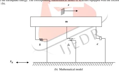
Consider a single structure which is equipped with a friction damper as shown in the Fig.1 (a).
(a) Friction damper equipped in a SDOF Structure
This structure is a single-degree-of-freedom system. Friction damper is a passive energy dissipating devices that is used to dissipate the earthquake energy. The corresponding mathematical model of structure equipped with the friction damper is shown in Fig. 1 (b).
(b) Mathematical model
Fig. 1 Structural model of SDOF structure equipped with friction damper. (a) Friction damper equipped in a SDOF Structure. (b) Mathematical model.
Equation of motion for SDOF structure
Let m, cand kbe the mass, damping co-efficient and stiffness of structure. The system is subject to the earthquake motion which is given by
𝑚𝑥̈ + 𝑐𝑥̇ + 𝑘𝑥 = - 𝑚𝑥𝑔̈ + 𝑓𝑑 (1)
where𝑥is displacement, 𝑥̇ is velocity and 𝑥̈ is acceleration.
Michalakis Constantinous at el. (1990) proposed frictional forces using a Wen’s equation (1976).
STRUCTURE
k fd
c
𝒙̈𝒈
x
IJEDR1502208
International Journal of Engineering Development and Research (www.ijedr.org)1274
𝑓𝑑 = µNZ (2)where 𝑓𝑑 is a damping force, µ is friction coefficient and N is clamping force, Z is Hysteretic dimensionless quantity. The
value of friction coefficient is constant. Non–linear first order differential equation is expressed as
qdZ A x
1
x Z Z n1
x Z ndt
(3)
where 𝑥̇ is a initial velocity. At initial stage it is taken equal to zero andq is the yield displacement.
1,, n and A are the dimensionless parameter of hysteresis loop. Shape of loop will depend upon
1,
, n and A. The recommended values for the above parameters are given as;q
= 0.25mm, A=1,
1= 0.9,
= 0.1 and n = 2. As a result, the governing equations of motion are solved in the incremental form using Newmark’s γ, β method assuming linear variation of acceleration over a small time interval, ∆𝑡. The iteration is required due to the dependence of Z on the response of the system at the end of each time step.Two SDOF structure connected with friction damper
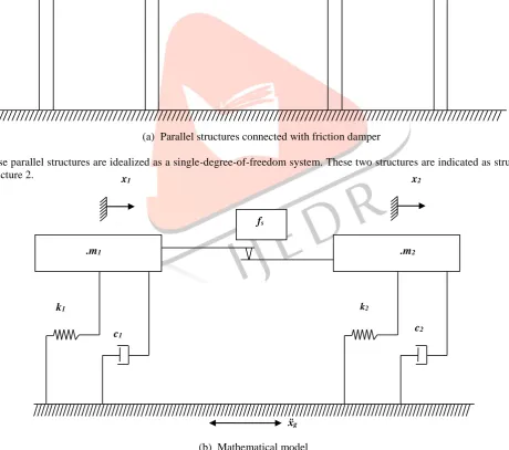
Consider two parallel structures which are connected with friction damper as shown in Fig. 2 (a).
(a) Parallel structures connected with friction damper
These parallel structures are idealized as a single-degree-of-freedom system. These two structures are indicated as structure 1 and structure 2.
(b) Mathematical model
Fig. 2 Structural model of two parallel SDOF structures connected with a friction damper. (a) Parallel structures connected with friction damper. (b) Mathematical model.
These two parallel structures are connected by friction damper and friction damper is represented by a viscoplasticity model. The frictional force mobilized in the damper has typical viscoplasticity characteristics. The space between these two parallel
Structure - 1 Structure - 2
FRICTION DAMPER
ẍg
c1 c2
k1 k2
x1 x2
.m1 .m2
IJEDR1502208
International Journal of Engineering Development and Research (www.ijedr.org)1275
structures is occupied by the friction damper. The corresponding mathematical model of structures connected with the friction damper is shown in Fig. 2 (b).Let m1, c1 and k1 be the mass, damping co-efficient and stiffness respectively of structure 1. Similarly m2, c2 and k2 denote the corresponding parameters of structure 2. The system is subjected to the earthquake motion and depends upon the system parameters and excitation level, when these parallel connected structures vibrate together, no slip will occur in the friction damper.
Let η be the mass ratio and λ be the frequency ratio of two structures, respectively, expressed as
Mass ratio (η) = 𝑚1
𝑚2 (4)
Frequency ratio (λ) = ω2
ω1 (5)
On the other hand, the numerical models are continuous and the required continuity is automatically maintained by the hysteretic displacement component used in the viscoplasticity model. Due to continuity of numerical model, they are preferred over the analytical model.
Non-slide mode- Both the structure vibrates together as a single-degree-of-freedom system during non slip mode under ground excitation. When slippage does not occurs the structure is said to be in a non-slide mode. The equation of motion for the combined system is given by
𝑚𝑐𝑥̈𝑐 + 𝑐𝑐𝑥̇𝑐+ 𝑘𝑐𝑥𝑐 = - 𝑚𝑐𝑥̈𝑔 (6)
where 𝑚𝑐 = 𝑚1+ 𝑚2 , 𝑐𝑐= 𝑐1+ 𝑐2 , 𝑘𝑐 = 𝑘1 + 𝑘2 are the mass, damping co-efficient and stiffness of the combined system,
respectively and 𝑥𝑐 , 𝑥̇𝑐 , 𝑥̈𝑐 are the displacement, velocity and acceleration of the combined system respectively; and 𝑥̈𝑔is the
ground acceleration respectively. By considering the dynamic equilibrium of structure 1 and structure 2 the frictional force in the damper can be obtained. Thus the non slip mode of the damper is valid until the following inequalities hold good.
| 𝑚1 (𝑥̈𝑐+ 𝑥̈𝑔) + 𝑐1𝑥̇𝑐 + 𝑘1𝑥𝑐 | ≤ 𝑓𝑠 (7)
| 𝑚2 (𝑥̈𝑐+ 𝑥𝑔̈ ) + 𝑐2𝑥̇𝑐+ 𝑘2𝑥𝑐 | ≤ 𝑓𝑠 (8)
where 𝑓𝑠 is a slip force.
Slip mode- When slip occurs between the two structures, the system is said to be in slip mode. The condition for initiation of slippage is written as
| 𝑚1 (𝑥̈1+ 𝑥̈𝑔) + 𝑐1𝑥̇1 + 𝑘1𝑥1 | > 𝑓𝑠 (9)
| 𝑚2 (𝑥̈2+ 𝑥̈𝑔) + 𝑐2𝑥̇2+ 𝑘2𝑥2 | > 𝑓𝑠 (10)
where 𝑥1, 𝑥2 are the displacements of structure1 and structure 2. The equations of motion of two connected structures in the
slip mode are given by
𝑚1𝑥̈1+ 𝑐1𝑥̇1+ 𝑘1𝑥1 = - 𝑚1𝑥̈𝑔+ 𝑓𝑠Z (11)
𝑚2𝑥̈2+ 𝑐2𝑥̇2+ 𝑘2𝑥2 = - 𝑚2𝑥̈𝑔- 𝑓𝑠Z (12)
where 𝑓𝑠 is a slip force. Till the relative velocities in the friction damper become zero then coupling system of structure will
remain in the slip mode. Thus velocity at structure 1 is equal to velocity at structure 2, i.e 𝑥̇1=.𝑥̇2It should be noted that during
slip-slip mode, Z is taken value of ±1. During stick-stick mode the absolute value of Z is taken as less than unity. {Z = ±1} slip-slip mode
{Z = less than unity} stick-stick mode Governing equations of motion for two parallel SDOF structures
The two SDOF structure are symmetric with their symmetric planes in the alignment. The equations of motion for this system are expressed as
From Eqn. (11) and (12)
𝑚1𝑥̈1+ 𝑐1𝑥̇1+ 𝑘1𝑥1 = - 𝑚1𝑥̈𝑔+ 𝑓𝑠Z
𝑚2𝑥̈2+ 𝑐2𝑥̇2+ 𝑘2𝑥2 = - 𝑚2𝑥̈𝑔- 𝑓𝑠Z
IJEDR1502208
International Journal of Engineering Development and Research (www.ijedr.org)1276
[𝑚01 𝑚02] {
𝑥1
𝑥2̈
̈
} + [𝑐01 𝑐0
2] {
𝑥1̇
𝑥2̇}
+ [𝑘01 𝑘0
2] {
𝑥1
𝑥2} = [
−𝑚1 0
0 −𝑚2] {
1 1} 𝑥𝑔̈ + [
𝑓𝑆𝑍
−𝑓𝑆𝑍]
(13)
𝑀𝑋̈ + 𝐶𝑋̇ + 𝐾𝑋 = −𝑀𝐼𝑥̈𝑔 + 𝐹𝐷 (14)
where M, C and K are the mass, damping and stiffness matrices of the combined system, respectively and these are expressed as
M = [𝑚01 𝑚0
2] C = [
𝑐1 0
0 𝑐2] I = {
1 1}
K = [𝑘01 𝑘0
2]
FD = [
𝑓𝑆𝑍
−𝑓𝑆𝑍]
FD is a vector consisting of the forces in the friction dampers; 𝑋 is the floor displacement vector. 𝑋̇ is velocity vector or 𝑋̈ is
acceleration vector.
Two parallel structures which are connected with a friction damper by using Viscoplasticity model. Viscoplasticity model is proposed to model the force in the friction damper connecting two parallel structures. The equation of motion for the two connected structure with is written as.
𝑚1𝑥̈1+ 𝑐1𝑥̇1+ 𝑘1𝑥1 = - 𝑚1𝑥̈𝑔+ 𝑓𝑑 (15)
𝑚2𝑥̈2+ 𝑐2𝑥̇2+ 𝑘2𝑥2 = - 𝑚2𝑥̈𝑔- 𝑓𝑑 (16)
where 𝑓𝑑 denote a damping force. This is calculated on the basis of mode of vibration. This viscoplasticity model is based on
the principal of theory of viscoplasticity. It is considered as a modified viscoplasticity model. From Eq. (2) 𝑓𝑑 = µNZ
Damping force is taken equal to 𝑓𝑑 = µNZ. Where µ is friction coefficient and N is clamping forces. Z is Hysteretic
dimensionless quantity. The non linear first order equation for connected structure-
1
2 1 1 2 1 2 1
n n
dZ
q A x x x x Z Z x x Z
dt
(17)
All the parameters are similar to the Eq. (3).
2 1
x x is relative velocity.
Solution for equations of motion
The frictional force mobilized in the friction damper is a non-linear function of displacement and velocity of the system. As a result, the governing equations of motion are solved in the incremental form using Newmark’s γ, β method assuming variation of acceleration over a small time interval, ∆𝑡.
𝑥 ̇𝑖+1 = 𝑥̇𝑖 + [(1 − 𝛾)∆𝑡]𝑥̈𝑖 + (𝛾∆𝑡)𝑥̈𝑖+1 (18)
𝑥𝑖+1 = 𝑥𝑖 + (∆𝑡)𝑥̇𝑖 + [(0.5 − 𝛽)(∆𝑡)2]𝑥𝑖 + [𝛽(∆𝑡)2]𝑥̈𝑖+1 (19)
The parameters 𝛽 and 𝛾 define the variation of acceleration over a time step and determine the stability and accuracy characteristics of the method. Typical selection for 𝛾 is 1
2 and 1 6 ≤ 𝛽≥
1
4 is satisfactory from all points of view, including that of
accuracy. These two equations, combined with the equation of motion at the end of the time step, provide the basis for computing𝑥𝑖+1, 𝑥̇𝑖+1 and 𝑥̈𝑖+1 at time 𝑖 + 1 from the known 𝑥𝑖, 𝑥̇𝑖 and 𝑥̈𝑖 at time 𝑖. For viscoplasticity model, an iterative
procedure is used for evaluating the incremental and dependence of Z on the response of the system at the end of each time step. Thus a fourth order Runge-kutta method is employed for the solution of the first-order differential equation (referred Eq. 17).
III. RESULTS AND DISCUSSION
For the present study, SDOF structure and two parallel structures are considered. The floor mass and stiffness are considered to be uniform for both the cases. The masses of two building are assumed to be same and the damping ratio in each structure is taken as 5% (Concrete structure). Frequency ratio λ is considered equal to 2 (ω1 =0.908π rad/sec, ω2 = 1.816π rad/sec) and mass
IJEDR1502208
International Journal of Engineering Development and Research (www.ijedr.org)1277
other hand, when slip force increases the acceleration get decrease up to certain value after that when there is decrease in the slip force the acceleration get increased. Thus value where acceleration starts to increase is selected as optimum slip force.Discussion and results for SDOF Structure
(a) (b)
Fig. 3
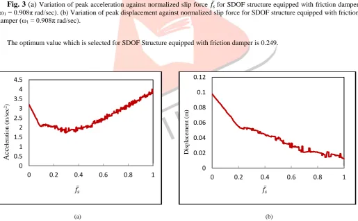
(a)
Variation of peak acceleration against normalized slip force 𝑓̅𝑠for SDOF structure equipped with friction damper(ω1 = 0.908π rad/sec). (b) Variation of peak displacement against normalized slip force for SDOF structure equipped with friction
damper (ω1 = 0.908π rad/sec).
The optimum value which is selected for SDOF Structure equipped with friction damper is 0.249.
(a) (b)
Fig. 4
(a)
Variation of peak acceleration against normalized slip force 𝑓̅𝑠for SDOF structure equipped with friction damper(ω = 1.816π rad/sec). (b) Variation of peak displacement against normalized slip force for SDOF structure equipped with friction damper (ω = 1.816π rad/sec).
The optimum value which is selected for SDOF Structure equipped with friction damper is 0.318. 0
0.05 0.1 0.15 0.2 0.25
0 0.2 0.4 0.6 0.8 1
Disp
lac
em
en
t
(m
)
0 0.5 1 1.5 2 2.5 3 3.5 4 4.5
0 0.2 0.4 0.6 0.8 1
Acc
elera
ti
o
n
(m
/se
c
2)
0 0.02 0.04 0.06 0.08 0.1 0.12
0 0.2 0.4 0.6 0.8 1
Disp
lac
em
en
t
(m
)
𝑓̅𝑠 𝑓̅𝑠
0 0.2 0.4 0.6 0.8 1 1.2 1.4 1.6
0 0.2 0.4 0.6 0.8 1
Ac
ce
lera
ti
o
m
(m
/se
c
2)
𝑓̅𝑠 𝑓̅𝑠
IJEDR1502208
International Journal of Engineering Development and Research (www.ijedr.org)1278
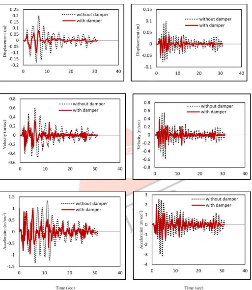
ω1 = 0.908π rad/sec ω2 = 1.816π rad/sec
Fig. 5 Time histories of displacement, velocity and acceleration of SDOF Structure equipped with friction damper for two different natural frequencies.
-0.2 -0.15 -0.1 -0.05 0 0.05 0.1 0.15 0.2 0.25
0 10 20 30 40
Disp lac em en t (m ) without damper with damper -0.1 -0.05 0 0.05 0.1 0.15
0 10 20 30 40
D isp la ce m en t (m
)
without damper with damper -0.6 -0.4 -0.2 0 0.2 0.4 0.6 0.80 10 20 30 40
Ve lo cit y (m /se c ) without damper with damper -0.8 -0.6 -0.4 -0.2 0 0.2 0.4 0.6 0.8
0 10 20 30 40
Ve lo cit y (m /se c) without damper with damper -1.5 -1 -0.5 0 0.5 1 1.5
0 10 20 30 40
Ac ce lera ti o n (m /se c 2) without damper with damper -4 -3 -2 -1 0 1 2 3
0 10 20 30 40
Ac ce lera ti o n (m /se c 2
)
without damper with damperIJEDR1502208
International Journal of Engineering Development and Research (www.ijedr.org)1279
Table1. Seismic responses of SDOF structure equipped with damper (ω1 = 0.908π rad/sec).
Earthquake
Displacement (m)
Velocity (m/sec)
Acceleration (m/sec2)
Unconnected
Connected Unconnected Connected Unconnected
Connected
Imperial valley, 1940
0.19999 0.09798 (51.00)#
0.60382 0.33650 (44.27)#
1.63515 1.03474
(36.71)#
# Quantity within the parenthesis denotes the percentage reduction.
Table2. Seismic responses of SDOF structure equipped with damper (ω2 = 1.816π rad/sec).
Earthquake
Displacement (m)
Velocity (m/sec)
Acceleration (m/sec2)
Unconnected Connected Unconnected Connected Unconnected Connected
Imperial valley, 1940
0.09800 0.04539 (53.37)#
0.58832 0.32014 (45.55)#
3.20800 1.98501
(38.12)#
# Quantity within the parenthesis denotes the percentage reduction. Discussion and results for two SDOF Structures connected by friction damper
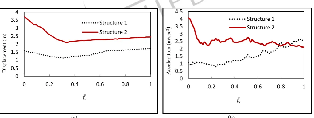
In case of two structures which are connected by friction damper, to arrive at the optimum slip force in the friction damper, the variation of peak displacement, peal acceleration are plotted with normalized slip force are shown in Fig. 6 for Imperial Valley earthquake motion.
(a) (b)
Fig. 6
(a)
Variation of peak displacement against normalized slip force 𝑓̅𝑠for two SDOF structures connected with frictiondamper (η = 2, λ =1). (b) Variation of peak acceleration against normalized slip force for two SDOF structures connected with friction damper (η = 2, λ =1).
It is observed that the response of both the structure are reduced up to a certain increase in the value of slip forces and with further increase in the value of the slip force they again increased.
0 0.5 1 1.5 2 2.5 3 3.5 4
0 0.2 0.4 0.6 0.8 1
Disp
lac
em
en
t
(m
)
Structure 1 Structure 2
0 0.5 1 1.5 2 2.5 3 3.5 4 4.5
0 0.2 0.4 0.6 0.8 1
Ac
ce
lera
ti
o
n
(m
/se
c
2
)
Structure 1 Structure 2
𝑓̅𝑠 𝑓̅
IJEDR1502208
International Journal of Engineering Development and Research (www.ijedr.org)1280
Therefore it is clear from the figures that optimum slip force exists to attain the minimum responses in both the structures. The optimum slip force is not exactly the same for both the structures; the optimum value is taken as the one, which gives the minimum sum of the responses of two structures.
Structure 1 Structure 2
-0.2 -0.15 -0.1 -0.05 0 0.05 0.1 0.15 0.2 0.25
0 10 20 30 40
Disp
lac
em
en
t
(m
)
without damper with damper
Structure 1
-0.1 -0.08 -0.06 -0.04 -0.02 0 0.02 0.04 0.06 0.08 0.1 0.12
0 10 20 30 40
Disp
lac
em
en
t
(m
)
without damper with damper
Structure 2
-0.6 -0.4 -0.2 0 0.2 0.4 0.6 0.8
0 10 20 30 40
Ve
lo
cit
y
(m
/sse
c)
without damper with damper
Structure 1
-0.8 -0.6 -0.4 -0.2 0 0.2 0.4 0.6 0.8
0 10 20 30 40
Ve
lo
cit
y
(m
/se
c)
without damper with damper
IJEDR1502208
International Journal of Engineering Development and Research (www.ijedr.org)1281
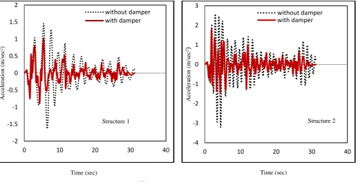
Fig. 7 Time histories of displacement, velocity and acceleration of two SDOF Structures connected with friction damper.
Table3. Seismic responses of two SDOF structures connected with friction damper.
Earthquake Structure
Displacement (m)
Velocity (m/sec)
Acceleration (m/sec2)
Unconnected Connected Unconnected Connected Unconnected Connected
Imperial Valley,1940
1 0.19999 0.08906
(55.46)#
0.60382 0.32471 (46.22)#
1.63515 1.02103 (37.55)#
2 0.09800 0.03807
(61.15)#
0.58823 0.30570 (48.03)#
3.20800 1.77728 (44.59)#
# Quantity within the parenthesis denotes the percentage reduction.
IV. CONCLUSION
Under the Imperial Valley earthquake excitation, the behavior of SDOF structure equipped friction damper and two parallel structures connected with a friction damper is worked out. The governing equations of motion are formulated for SDOF structure and two SDOF structures during non-slip and slip modes of damper. A numerical model (Viscoplasticity Model) is used to evaluate the friction forces in the damper. The result obtained in this study provides information towards the design of coupling friction damper. It is found that friction damper is more effective in reducing the earthquake response of two parallel structures connected by it. There exists an optimum slip force of friction dampers and minimize the earthquake response of parallel connected structures. When there exist slight variation in the optimum slip force of damper than it does not have much effect on the optimum responses and hence, small variations in the slip load over life of the structure does not warrant any adjustments of replacement of friction damper.
-2 -1.5 -1 -0.5 0 0.5 1 1.5 2
0 10 20 30 40
Ac
ce
lera
ti
o
n
(m
/se
c
2)
without damper with damper
Structure 1
-4 -3 -2 -1 0 1 2 3
0 10 20 30 40
A
cc
ele
ra
tio
n
(m
/se
c
2
)
without damper with damper
Structure 2
IJEDR1502208
International Journal of Engineering Development and Research (www.ijedr.org)1282
REFERENCES
[1] A.V. Bhaskararao and R.S. Jangid, “seismic analysis of structures connected with friction damper,” Engineering Structure, vol.28, pp.690-703, 2006.
[2] Cedic Marsh, “The control of building motion by friction damper,” 12th World Conference on Earthquake Engineering, 2005,
[3] Westermo B., “The dynamics of inter-structural connection to prevent pounding,” Earthquake Engineering and Structural Dynamics, vol.18, pp.687-699, 1989.
[4] A.V. Bhaskararao and R.S. Jangid, “Harmonic response of adjacent structures connected with a friction damper,” Journal of Sound and Vibration, vol.292, pp.710-725, 2006.
[5] I. Lopez and H. Nijmeijer, “Prediction and validation of the energy dissipation of friction damper,” Journal of Sound and Vibration,vol.328, pp.396-410, 2009.
[6] Hong-nan Li, Su-Yan Wang, Gangbring Song and Guanglei Liu, “ Reduction of seismic forces on existing building with newly constructed additional stories including friction layer and dampers,” Journal of Sound and Vibration, vol.269, pp.653-667, 2004.
[7] I. Lopez, J.M. Busturia and H. Nijmeijer, “Energy dissipation of friction damper,” Journal of Sound and Vibration, vol.278, pp.539-561, 2004.
[8] S. Chatterjee, “Resonant locking in viscous and dry friction damper kinematically driving mechanical oscillators,” Journal of Sound and Vibration, vol.332, pp.3499-3516, 2013.
[9] Yong-min Park and Kwang-joon Kim, “Semi-active vibration control of space truss structure by friction damper for maximization of model damping ratio,” Journal of Sound and Vibration, vol.332, pp.4817-4828, 2013.
[10]Rosario Mantuori, Elide Nastri and Vincenzo Piluso, “Thoery of plastic mechanism control for the seismic design of braced frames equipped with friction dampers,” Mechanics Research Communications, vol.58, pp.112-123, 2014.
[11]Habib Saeed Monir and Keyan Zeynail, “A modified friction damper for diagonal bracing of structure,” Journal of construction Steel Research, vol.87, pp.17-30, 2013.
[12]Lyan –Ywan Lu, “Semi-active model control for seismic structures with variable friction dampers,” Engineering Structures, vol.26, pp.437-454, 2004.
[13]C.L. Ng and X.L. Xu, “Semi- active control of a building complex with variable friction dampers,” Engineering Structure, vol. 29, pp.1209-1225, 2007.
[14]Sang Hyun Lee, Ji-Hun Park, Sung-Kyung Lee and Kyung-Won Min, “Allocation and slip of friction damper for a seismically excited building structure based on storey shear force distribution,” Engineering Structure, vol.30, pp.930-940, 2008.
[15]Wen Y. K., “Method of random vibration of hysteretic system,” Journal of the Engineering Mechanics Division, vol.102, paper no.2, march/april 1976.
[16]Michalakis Constantinou, Anoop Mokha and Andrei Reinhorn, “Teflon bearing in base isolation Part 2: modeling,” Journal of Structural Engineering, vol.116, pp.455-474, 1990.
[17]J. Young seong, Kyung-Won Min and Jung Chul Kim, “Analytical investigation of an SDOF building structure equipped with friction damper,” Nonlinear Dyn, DOI:10.1007/s11071-012-0446-7, 2012.
[18]Shilpa G. Nikam, S.K. Wagholikar and G.R. Patil, “Seismic energy dissipation of a building using friction damper,” International journal of Innovative Technology and Exploring Engineering, vol.3, pp.2278-3075, 2014.
[19]Semra Sirin Kiris and M Hasan Boduroglu, “Earthquake parameters affecting the performance of an RC frame with friction damper, “Soil Dynamics and Earthquake Engineering, vol.55, pp.148-160, 2013.
[20]X.L. Xu and B. Chen, “Integrated vibration control and health monitoring of building structures using semi-active friction damper: part 1 methodology,” Engineering structure, vol.30, pp.1789-1801, 2008.
[21]Hong-Nan li and Da-Hai Zhao, “Cntrol of structure with semi-active friction damper by intelligent Algorithm,” International conference on fuzzy system, Canada, pp.1584-1590, 2006.
[22]Hong Nan Li, Jun Li and Gangbing song, “13th Medlterranean Conference on control and Automation, Limassal, Cypus, June
27-29, pp.310-315, 2005.