IJEDR1402199
International Journal of Engineering Development and Research (www.ijedr.org)2544
Optimal Placement of Phasor Measurement Units
using Integer Linear Programming
Naydu Vipul G.
1, A. B. Parmar
21M E Scholar, 2Assistant Professor
Department of Electrical Engineering, L E College, Morbi, GTU 1
[email protected], 2 [email protected]
________________________________________________________________________________________________________
Abstract— This paper solves the optimal placement problem of phasor measurement units (PMUs) so as to make a system completely observable. Observability assessment is done by the aid of the topological observability rules. This paper presents a generalized integer linear programming formulation for cases including redundant PMU placement, full observability. In order to improve the speed of convergence, an initial PMU placement is provided by graph-theoretic procedure. The simulation results of proposed approach are presented for several IEEE test systems.
Keywords— Observability analysis, optimal placement, Integer linear programming, phasor measurement unit
________________________________________________________________________________________________________
I. INTRODUCTION
PHASOR Measurement Unit (PMU) was introduced in 1990s. PMU is a devices that provide synchronized measurements of real-time phasors of voltages and currents. Synchronization is achieved by same-time sampling of voltage and current waveforms using timing signals from the Gobal Positioning System Sattelite (GPS). Synchronized phasor measurements have took the power system monitoring, control, and protection to a new level [1]. PMUs have various applications such as post-mortem analysis, adaptive protection, system protection schemes, and state estimation. One of the major issues that need to be addressed in the emerging technology of PMUs is site selection. The cost of the PMU is high so it will limit the number of installation in the system.
For PMU placement problem, the constraint condition is the observability of power system and objective function is minimizing the cost of PMU systems. In this paper algorithm for optimal placement of PMUs by using integer programming is developed.
In this paper the concept of full topological observability of the power system is adopted as the constraint condition and its principles or rules are described in section-II. PMU placement problem formulation is shown in section-III. Section-IV shows the linear algorithm. Section-V shows simulation results for standard IEEE test systems. Section-VI gives the conclusion and possible future work.
II.OBSERVABILITY
In a power system, if a node voltage of one bus is directly measured or calculated by using other known node voltage and branch currents, then that bus is said to be observable. If all buses are observable in the system then the power system can be defined as fully observable.
There are two methods to find observability of a power system: numerical and topological. Numerical observability consists large computations and can be easily affected by cumulative error, while topological observability method is fast and practical.
In PMU placement problem, three rules can be used to analyse the topological observability if each bus within the target power system.
Rule 1: a bus with PMU installation is observable, and its adjacent buses are all observable because their voltages can be calculated by Ohm‟s law with the help of the PMU measurement;
Rule 2: if a bus is adjacent to an observable zero-injection bus (a bus with zero net injection of power from the connected loads and generators) to which all other adjacent buses are observable, then the bus is observable because its voltage can be calculated by KCL and Ohm‟s law;
Rule 3: if all buses adjacent to a zero-injection bus are observable, then the zero-injection bus is observable because its voltage can be calculated by KCL and Ohm‟s law.
III.PMUPLACEMENT PROBLEM FORMULATION
IJEDR1402199
International Journal of Engineering Development and Research (www.ijedr.org)2545
is the cost of the PMU installed at bus i;f (X )= vector function, whose value is non-zero if the corresponding bus is solvable by using the given measurement set and zero otherwise.
î = unit vector.
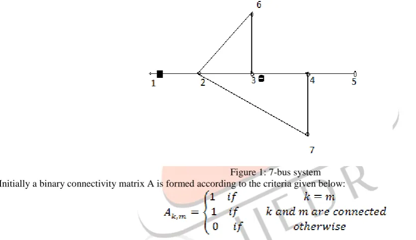
A PMU placed at a bus implies that the voltage of that bus and the buses connected to that bus are available or solvable. The procedure of building the constraints for the PMU placement problem is explained with the help of 7 bus system shown in figure 1.
Figure 1: 7-bus system Initially a binary connectivity matrix A is formed according to the criteria given below:
The connectivity matrix can also be directly obtained from the bus admittance matrix by transforming it into binary form. For the 7 bus system given in figure 1 the connectivity matrix is given as follow:
(2)
Case 1: No conventional measurements and/or zero injections.
IJEDR1402199
International Journal of Engineering Development and Research (www.ijedr.org)2546
.…(3)Here the operator “+” serves as the logical “OR” and each vector function that is f1 to f7 has to be greater than one in order to make the system observable.
The constraints mean that if bus 2 has to be made observable a PMU is needed to be placed at any of the buses among buses 1,2,3,6 and 7. It can also be considered as, if a PMU is placed at bus 2 then the buses 1,2,3,6 and 7 will be observable.
Constraints associated with bus 1 and 2 can be given as below:
The first constraint implies that at least one PMU must be placed at either bus 1 or bus 2 (or both) to make bus 1 observable. Similarly, indicates that at least one PMU must installed at any one of the buses 1, 2, 3, 6, or 7 to make bus 2 observable.
Case 2: A system with injection measurements some of which may be zero injection pseudo-measurements.
In figure 1, bus 3 is assumed to be a zero injection bus. In this case, net injected current at bus 3 is known so it is easy to find the phasor voltages at any one bus if the phasor voltage of any three out of the four buses 2, 3, 4 and 6 are known. Hence, the modified constraints associated with these buses will be given as below:
Note that the operator „.‟ serves as the logical “AND”.
The expressions for can be further simplified by using the following properties of the logical AND (.) and OR (+) operators: Given two sets A and B, where set A is a subset of set B, then and . For instance, substituting the expression for in the expression for , can be written as:
=
=
=
Note that the expression for should also include an extra product term given by , however this term will be neglected.
Carrying on with the simplifications, the product is eliminated because it is the subset of , which already exists in the expression. Using similar reasoning, and are also eliminated.
Then, substitute the expression of yields: =
IJEDR1402199
International Journal of Engineering Development and Research (www.ijedr.org)2547
( ,
Similarly, simplification logic to all other expressions will yield:
Constraints corresponding to all other buses will be same as given in equation (3).One exception is the constraint for bus 3 where the injection is known will be eliminated from the constraint set. The reason for doing this is that by removing the constraints associated with injection buses their effects are indirectly taken into account by the product terms augmented to the constraints associated with the neighbouring buses.
Case 3: A system with injections as well as flow measurements
The modifications needed in the formulation for this case will again be explained using the 7-bus example, in which a flow measurement (P and Q) is added for branch 1-2.
Note that having a flow measurement along a given branch, allows the calculation one of the terminal bus voltage phasors when the other one is known.
Constraints for buses 1 and 2 are merged into a joint constraint as follows:
Which shows that if either one of the voltage phasors at bus 1 or 2 is observable, then the other one will be observable. Applying this modification to the constraints for the 7-bus system, the set of final constraints will be obtained as follows:
Note that, the constraints for buses 1 and 2 are merged into a single constraint and the constraint associated with bus 3 where there is an injection measurement, is eliminated as explained in case 2.
IV.THE LINEAR ALGORITHM
Creating a Node –Incidence Matrix for Power System
IJEDR1402199
International Journal of Engineering Development and Research (www.ijedr.org)2548
Fig. 2: IEEE-14 bus systemTo produce the node incidence matrix the rule is simple: If node i is connected to node j, then Aij =1, where i j and Aii=0. Normally A is a large sparse matrix. For example, for the IEEE 14-bus system,
A= [0 1 0 0 1 0 0 0 0 0 0 0 0 0 1 0 1 1 1 0 0 0 0 0 0 0 0 0 0 1 0 1 0 0 0 0 0 0 0 0 0 0 0 1 1 0 1 0 1 0 1 0 0 0 0 0 1 1 0 1 0 1 0 0 0 0 0 0 0 0 0 0 0 0 1 0 0 0 0 0 1 1 1 0 0 0 0 1 0 0 0 1 1 0 0 0 0 0 0 0 0 0 0 0 1 0 0 0 0 0 0 0 0 0 0 1 0 0 1 0 0 1 0 0 0 1 0 0 0 0 0 0 0 0 1 0 1 0 0 0 0 0 0 0 0 1 0 0 0 1 0 0 0 0 0 0 0 0 0 1 0 0 0 0 0 0 1 0 0 0 0 0 0 1 0 0 0 0 0 1 0 1 0 0 0 0 0 0 0 0 1 0 0 0 1 0]
It is easy to find out that there are 8 nodes with degree 3 or more. Here K=8 and n=14. so, the number of PMUs needed that is ,the only possible values for S between 3 and 4 using equation (1) and (2) .Now we want to find out the minimum number of PMUs, and the dominating set S. The basic idea of this algorithm is to test all possible node combinations by the observation rules, until one combination is found to be able to “observe” all the system. We call a test for a combination as a measurement. For the IEEE 14-bus system, the maximum number of measurements is number of combinations produce by selecting numbers of a group in between 3-4, who will converge, will give the required number of PMUs in the system. That is 70 for IEEE 14-bus system .We need to keep in mind that, in the implementation of the algorithm, we may not have to run all the 70 measurements to find out the S-set. The number of measurement before we get an S-set (which is usually not unique) can be any number between 1 and 70.
Algorithm for Finding The Minimum Number Of PMUs
Begin
1. Read in node-incidence matrix A with all buses (nodes) in the system says G. 2. Calculate the bounds of S.
3. Check the observability of the system by creating loop starting from the lower bound, to the upper bound:
a. Generate a node combination, e.g., {2, 4, 5}.These nodes are mounted with PMUs, thus observed. Save them in array O. b. Find out all nodes adjacent to these 3 or 4 nodes.
c. Save them in array O. 4. Find out all nodes that are not in O.
a. Pick up such a node j, use rule 4 to judge if it is observed. If yes, put j in O, and pick up another node and check. b. If all “not-in-O” nodes have been checked, compare O to the whole set G.
IJEDR1402199
International Journal of Engineering Development and Research (www.ijedr.org)2549
IEEE-30 bus 10 2, 4, 6, 9, 10, 12, 15, 18, 25, 27 Simulation results with zero injections
Test system No. of PMUs Bus location
IEEE-14 bus 3 2, 6, 9
IEEE-30 bus 7 3, 5, 10, 12, 18, 23, 27
VI.CONCLUSION
This paper proposes a generalized integer linear programming formulation for optimal PMU placement under different cases of redundant PMU placement, full observability and incomplete observability. This generalized formulation, considering the situations with and without zero injection measurements, shows that the problem of optimal PMU placement can be modeled linearly and can be solved by integer linear programming. The generalized formulation paves an efficient way for future research in PMU placement and related topics. From the simulation results we can see that the proposed algorithm is computationally efficient and can be used in practice.
REFERENCES
[1] G. T. Heydt, C. C. Liu, A. G. Phadke, and V. Vital, “Solutions for the crisis in electric power supply,” IEEE Comput.Appl. Power Mag., vol. 14, no. 3, pp. 22-30, Jul. 2001.
[2] “Assessment of Applications and Benefits of Phasor Measurement Technology in Power Systems,” GE Power Syst. Eng., EPRI Final Rep., Apr. 1997.
[3] L. Mili, T. Baldwin, and R. Adapa, “Phasor measurement placement for voltage stability analysis of power systems,” in Proc. 29th Conf. Decision and Control, Honolulu, HI, Dec. 1990.
[4] T. L. Baldwin, L. Mili, M. B. Boisen, and R. Adapa, “Power system observability with minimal phasor measurement placement,” IEEE Trans. Power Syst., vol. 8, no. 2, pp. 707-715, May 1993.
[5] J. Chen and A. Abur, “Placement of PMUs to enable bad data detection in state estimation,” IEEE Trans. Power Syst, vol. 21, no. 4, pp. 1608-1615, Nov. 2006.
[6] B. Milosevic and M. Begovic, “Nondominated sorting genetic algorithm for optimal phasor measurement placement,” IEEE Trans. Power Syst., vol. 18, no. 1, pp. 69-75, Feb. 2003.
[7] B. Xu and A. Abur, “Observability analysis and measurement placement for systems with PMUs,” in Proc. 2004 IEEE Power Eng. Soc. Conf. Expo., Oct. 10-13, 2004, vol. 2, pp. 943-946.
[8] B. Gou, “Optimal placement of PMUs by integer linear programming,” IEEE Trans. Power Syst., vol. 23, no. 3, pp. 1525-1526, Aug. 2008.