Article
1
Flexible abrasive tools for deburring and finishing of
2
holes in superalloys
3
Adrián Rodríguez 1, Asier Fernández 2, Luís Norberto López de Lacalle 3 and
4
Leonardo Sastoque Pinilla 4*.
5
1 Aeronautics Advanced Manufacturing Center, Zamudio 48170, Spain; Adrian.Rodriguez@ehu.eus
6
2 Aeronautics Advanced Manufacturing Center, Zamudio 48170, Spain; Asier.Fernandez@ehu.eus
7
3 Aeronautics Advanced Manufacturing Center, Zamudio 48170, Spain; Norberto.lzlacalle@ehu.eus
8
4 Aeronautics Advanced Manufacturing Center, Zamudio 48170, Spain; EdwarLeonardo.Sastoque@ehu.eus;
9
Corresponding author.
10
* Correspondence: cfaa2015@ehu.eus; Tel.: +34 688 673 836
11
12
Abstract: Many manufacturing sectors require high surface finishing. After machining operations
13
such as milling or drilling, undesirable burrs or insufficient edge finishing may be generated. For
14
decades, many finishing processes have been handmade-basis; this fact is accentuated when
15
dealing with complex geometries especially for high value-added parts.
16
In recent years, it’s a tendency of trying to automate as far as possible this kind of processes,
17
repeatability and time/money savings are main purposes. Based on that idea, the aim of this work
18
is to check new tools and strategies for finishing aeronautical parts, especially critical engine parts
19
made on Inconel 718, a very ductile nickel alloy. Automating edge finishing of chamfered holes is a
20
complicated but really important goal.
21
In this paper, flexible abrasive tools were used for this purpose. A complete study of different
22
abrasive possibilities was carried out, mainly focusing on roughness analysis and final edge results
23
obtained.
24
Keywords: Flexible abrasive tools; finishing; rounding edge; superalloys.
25
26
1. Introduction
27
Titanium alloys and nickel-base superalloys are widely used today in aerospace components,
28
commonly used in engines, considering that superalloys and concretely Inconel 718 are capable of
29
working in corrosive environment and high temperatures. Those materials can be used as part of gas
30
turbine engines, steam, nuclear components, chemicals, etc. There is a strong demand on
31
dimensional accuracy and surface roughness for these high-value components.
32
Drilling holes in aerospace components is often a delicate operation, the hole amplifies the
33
stress around it by a factor of two [1]. Moreover, it is often the last machining operation, with a
34
looming risk of making a scarp part due to a single bad hole. This circumstance determines the final
35
time used in the production of the part, and a lack of quality can guide to its rejection, having to be
36
especially taken into account the reliability of the process due to the costs already involved.
37
Therefore, it is a high value-added operation [2].
38
Currently in industrial practice, drilling process are widely used due to its versatility and the
39
short time invested in performing the task. However, these operations produces results with not
40
very high quality so it is required complementary operations such as dotted, re-drilling, reaming,
41
chamfering and edge finishing. This fact supposes a waste of time, both in subsequent cutting
42
processes and in tool changes. The "not very high quality" refers, basically, to the deviations that
43
occur in terms of diameter tolerances, surface roughness and burr formation; inherent phenomenon
44
in the process. Also, the effect of cutting parameters on the hole quality (circularity and hole
45
diameter) and tool wear during the drilling of super alloy Inconel 718 allowed to infer that cutting
46
speed and feed rate played a great role in the variation of deviation from circularity values. [3]. The
47
available literature regarding drilling on high strength materials is rather limited [4,5]. However, in
48
recent years there were further investigations in new techniques and processes to drill holes on these
49
alloys.
50
Among these new techniques, ultrasonic assisted machining is one of the most used. This is a
51
machining technology where a high frequency vibration (20kHz) with amplitude around 10µm,
52
overlaps the continuous movement of the cutting tool, providing an output power between 50W and
53
3000W [6]. The use of ultrasonic-assisted processes allows a reduction in cutting forces by 30-50%
54
[7], an improvement of the final surface quality, better chip evacuation and a longer tool life [8].
55
Other authors propose alternatives to traditional drilling. The idea is to use a ball-end milling
56
tool giving it a helical motion around the hole. Regarding the helical milling, there are two similar
57
helical milling techniques: Ball Helical Milling (BHM) and Contouring Ball Helical Milling (CBHM)
58
[9]; results were quite good in quality but times were far from those obtained in twist-drilling
59
operation, or in other processes [10-11] Takt-time in aeroengine manufacturing prevent in many cases
60
to replace the drilling with twist drills, so edge burrs and not very good finishing are common
61
issues. In emerging processes, the plasticity of metal is also key, as shown in [12-13]
62
In this paper, brushing techniques using abrasive flexible tools are studied. The aim is to
63
implement these tools for the finishing process, being able to improve the surface finish obtained on
64
one hand, and get the rounding of edges in countersunk holes on the other. Flexible hone tools are
65
available in Silicon Carbide, Aluminum oxide, Zirconia Alumina, Boron Carbide, Tungsten carbide
66
and even in other grades, with diameter ranging from 4 to 1000 mm.
67
In this work, different tools available in the state of art are presented. Tests were carried out in
68
order to make a first approach to the use of these tools, with interesting results are shown below.
69
2. Flexible abrasive tools
70
Companies such as Brush Research Manufacturing (BRM) have a long history of solving
71
difficult finishing problems with brushing technology. The term "brush" is commonly associated to
72
the classic twisted wire brushes or the nylon ones used for deburring or edge blending. It is a flexible
73
and elastic abrasive tool, ideal for soft cutting in finishing operations, "plateau honing", cylinder
74
liners deburring, hydraulic and pneumatic components, as well as other industry sectors such as
75
aeronautics, automotive parts, screw machining, etc.
76
Those are a general-purpose tools (Figure 1) which versatility stems from the small abrasive
77
balls overlapped at the end of a nylon filament. Each ball is independent of the others; this fact
78
ensures the centering and auto-alignment with the hole. Having complete control of process
79
parameters and identifying and assessing the influence on the final surface is essential for an
80
efficient implementation of these tools in CNC machines and robots.
81
82
83
(a) (b)
Air
Plate
Turn movement
Brush
Figure 1. (a) Tools with different abrasive qualities. (b) Tool detail (3x).
85
One application of these flexible tools is the surface finishing and the edge blending of holes
86
made in aeronautic alloys, such as Inconel 718 and Ti6Al4V. A wide range of abrasives and grit sizes
87
are offered by BRM and other companies. This implies the necessity to carry out a comparison
88
between the different abrasive grades. Tests' results of different abrasive types and grain sizes are
89
presented in this work. The parameter measured in this first approach is the final roughness of the
90
brushed holes. Table 1 shows the variety of tools used. (Prices are shown because in some cases are
91
double than other solutions.)
92
Table 1. Different flexible abrasive tools used in tests.
93
Code Abrasive Grit Sizes Nominal diameter Web Price
SC10 Silicon Carbide 180 10mm ≈ 12 $/un SC11 Silicon Carbide 180 11mm ≈ 12 $/un SC11 - 400 Silicon Carbide 400 11mm ≈ 23 $/un BC11 Boron Carbide 180 11mm ≈ 15 $/un Di11 Diamond 2500 C Mesh 11mm ≈ 30 $/un
3. Previous tests on Ti6Al4V alloy
94
Preliminary tests on Ti6Al4V alloy were carried out. This alloy was used firstly because is more
95
economical, easier to buy and with better machinability than the superalloys, such as Inconel 718.
96
Titanium plates were used (200x100x7.5mm dimensions); the main aim of these tests is to stablish a
97
first approach to the process before doing it in Inconel 718. On the other hand, titanium alloys are
98
used not only in engines but in airframe key parts, which are joining the wings to the airplane body.
99
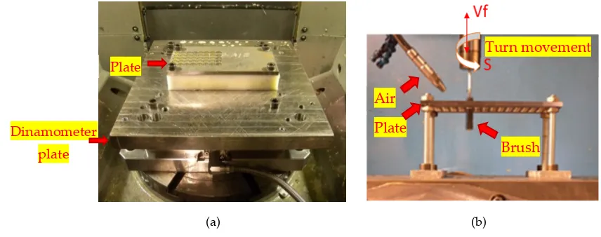
Prior to conducting the brushing tests, 80 holes with 10.7mm diameter were drilled on the
100
plates. The following conditions are used in previous drilling: Vc = 35m/min and f = 0.12mm/rev.
101
Figure 2 shows the experimental set-up.
102
103
104
105
106
107
108
109
110
111
112
(a) (b)
113
Figure 2. (a) Drilling Set-up. (b) Brushing Set-up.
114
As shown in Figure 1 and gathered in Table 1, five different flexible abrasive tools were used.
115
With each different brush, 16 holes have been made at these brushing conditions: Vc = 60m/min and
116
f = 0.5mm/rev. Figure 3 shows the results of roughness measurement, both drilled holes and the
117
brushed ones. Firstly, the surface quality obtained in previous drilling with the conditions used is
118
quite good, averaging around 0.5µm Ra. The main problem is the results dispersion, varying the Ra
119
roughness parameters from 0.29µm to 1.17µm.
120
After brushing with the five different flexible abrasive tools, the roughness parameters
121
decreased and the results dispersion is lower. The best brush type for this material in terms of
122
Dinamometer
plate
surface roughness is the SC11-400, as it reduces the average Ra roughness up to 0.25µm, with values
123
between 0.2µm and 0.3µm. (Figure 3).
124
125
Figure 3. Ra [µm] and Rz [µm] roughness values after drilling and after finishing Ti6Al4V
126
4. Test on Inconel 718 superalloy
127
Basing on data from preliminary tests carried out on Ti6Al4V, it is known that the five different
128
flexible abrasive brushes were able to reduce the roughness parameters. Moreover, it is an easy and
129
economical finishing process that can be carried out in machine tools.
130
On the other hand, preliminary tests show a low cutting capacity. It is difficult to make a
131
chamfer on a hole or deal with large burrs because removing that much material is impossible.
132
However, these brushes could be useful in order to finishing surfaces, rounding edges or cross-hole
133
deburring [9]. For these reasons, experimental tests were carried out on Inconel 718 plates, which is a
134
commonly used material in aerospace components working at high temperatures. This is a difficult
135
material to machine, so the soft cut of these brushes may be insufficient.
136
In this case, Inconel 718 plates were used: 200x100x7.5mm dimensions, similar to those used in
137
preliminary tests in Titanium. The tests were carried out in an Ibarmia ZV25 milling machine, with a
138
spindle with 25 KWs. Regarding the previous drilling, the Table 2 shows two different conditions
139
used.
140
Table 2. Conditions used drilling Inconel 718
141
Vc [m/min] f [mm/rev] S [rpm] Vf [mm/min] No. Holes
“A” Conditions 20 0.06 595 35.7 40 “B” Conditions 25 0.06 744 44.6 40
4.1. “A” Conditions.
142
Two different cutting conditions in previous drilling in Inconel 718 were tested. The first
143
conditions are established by the tool manufacturer, the second ones are rather demanding in order
144
to reduce processing time and increase productivity. The aim is to compare the surface roughness
145
results after brushing. The drilling parameters in "A" conditions are c = 20m/min and f = 0.06mm/rev.
146
After performing the drilling, brushing tests were carried out. In this case the same brushing
147
conditions as in preliminary test have been used (Vc = 60m/min and f = 0.5mm/rev).
148
Figure 4 shows roughness results obtained before and after brushing. The surface roughness
149
obtained after drilling is moderately good (around 0.5µm Ra) thanks to the conservative drilling
150
conditions used. After brushing, the results show that the roughness values decrease somewhat, but
151
not significantly. In the case of SC10 brush, the roughness becomes worse. This implies that for this
152
material and using the drilling conditions given by the manufacturer, these SC10 brushes are not
153
suitable. As for the rest of the tests, like what happened in Titanium, the best roughness results are
154
achieved with SC11-400 brushes. However, BC11 brush provides similar roughness values and less
deviation in the results. In addition, BC11 brushes are cheaper and with less wear after brushing
156
than SC11-400, so BC11 is the most suitable in this case.
157
158
Figure 4. Ra [µm] and Rz [µm] roughness values after drilling and after finishing Inconel718
159
The results obtained in this case also show that using these drilling conditions it is too
160
unproductive to execute a brushing operation because the surface improvement is roughly
161
inappreciable. In the following section, the brushing process in more demanding drilling conditions
162
is examined. In this case, the brushing process could be useful.
163
4.2. “B” Conditions.
164
In this section, the previous drilling conditions are: Vc = 25m/min and f = 0.06mm/rev. In this
165
way, the roughness results obtained after drilling were worse than in previous cases. However,
166
brushing could be useful in this case. Figure 5 show roughness results. The roughness values
167
observed before brushing were around Ra 0.9µm, with a large dispersion of results. After brushing,
168
the roughness parameters decreased to values lower than 0.65µm Ra. In this case, BC11 brush
169
provided the lowest roughness values and the lowest deviation of the results, so this was the most
170
convenient. Besides, the tool wear was not critical in this case.
171
172
Figure 5. Ra [µm] and Rz [µm] roughness values after drilling and after finishing Inconel718
173
As a note, results showed that the cutting ability of these brushes is limited, especially when
174
cutting low machinability materials such as Inconel 718. Therefore, great deburring and chamfering
175
of holes became impossible. However, once the hole is chamfered, rounding edges and surface
176
finishing can be done using the flexible abrasive brushes [11]. Figure 6 shows one of the
177
drilled-brushed holes. The process was the next: drilling, chamfering and brushed. The figure 6 and
178
Table 3 shows the rounding edge produced by brushes.
180
(a) (b)
181
Figure 6. (a) Hole section and detail of the chamfer and rounding edge. Image 1 (5x), Image 2 (10x),
182
Image 3 (10x). (b) Angle detail measured with optical means of the rounding edge of a hole section
183
(5x).
184
Table 3. Angle detail – Hole section of the rounding edge.
185
Angle/ ⁰ Apex X/mm Apex Y/mm
Angle 1 102.241 99.452 48.341
For years, edge finishing process has been handmade in many areas, but now the tendency is
186
trying to automate these finishing processes [12]. One automation possibility implies flexible
187
abrasive brushes. But others would be possible, such as using shape tools. In this case, the main
188
drawback is the correct tool positioning and also the tangents to the surface. In addition, it is
189
necessary to consider the fact that many of these holes are placed in curved areas or in difficult
190
access areas to a conventional milling tool. The main problem with the brushes is the lack of
191
repeatability and the rapid wear suffered.
192
Figure 7 shows some photographs of the brushes following their use. As mentioned above,
193
despite achieving the best results, SC11-400 brush is one of the most expensive, along with the
194
Diamond one. Besides, tool wear on these brushes is greater than the rest. To conclude, regarding
195
the tool wear, BC11 is the most appropriate option on materials such as Inconel 718 Moreover, in
196
some cases is also the best option regarding surface quality achieved.
197
198
Figure 7. Tool wear on three different brushes. New tool; after Inconel 718; after Ti6Al4V (3x)
199
200
Hole section of the rounding edge
1. 2.
3.
5. Automatic process
201
Polishing and deburring is a process with great automation possibilities, by means of robots
202
[13]. Force feedback control is the key aspect to be considered. Definition of a robotic cell for
203
applying the process is based on accessibility. Flexible brushes are applied on holes for different
204
aeroengine components, cases being produced on Inconel 718, Hastelloy or other nickel alloys are a
205
good task for them. Deburring and edge finishing will be always a step in the process chain. The idea
206
proposed is to work in high-automation mode, in following stages:
207
• Burr detection, for instance using structured blue light, or other optical means. The location of
208
random implies a random pattern
209
• Robotic deburring in brush manipulation: a robotic arm can use a spindle with the usual
210
low-torque to give brushed the required rotational speed.
211
• Final check: optical means will help, in cases of internal hole surface roughness, a roughness
212
meter measurement is obliged.
213
The proposed system for the automation process consists in a unique superfinished cell capable
214
of working in two different work modes, in particular, with a tool on a robot or with a piece on a
215
robot. In the first of the work modes (MOD1), the idea is to work on pieces of large dimensions (Ø
216
2400 mm, height 1500 mm, weight 2500 kg) mounted on a rotating table and working with tools
217
mounted on the robot, being this able to access the outer and inner areas of type pieces. The
218
materials to be worked in this case will be heat-resistant alloys with mechanical characteristics equal
219
to or higher than Inconel 718, Titanium 6-4, Jethete type stainless steel or similar. The operations to
220
be carried out will be diverse, highlighting operations of deburring, edge killing and polishing of
221
localized areas and holes, as well as measurement and control operations. In a second mode of work
222
(MOD2), we work with tools mounted in fixed posts, the piece being positioned mounted on the
223
manipulator robot. In this case the pieces to be treated will be units or sets coming from castings or
224
other types of components with maximum dimensions of approximately 1000x1000x1000 mm and
225
maximum weights of up to 120 kg. The materials will have characteristics similar to those indicated
226
for the MOD1 work mode and the operations to be carried out include cutting and sanding
227
processes as well as other operations such as those already mentioned for deburring, polishing and
228
measuring and control. Figure 8 shows the system use to apply the approach.
229
230
231
Figure 8. Robotic deburring: robot arm, structured-blue light devices, detail of holes with burrs.
232
6. Conclusions
233
Several contributions can be pointed out, namely:
• Preliminary tests on Ti6Al4V show that flexible abrasive brushes are able to reduce the
235
roughness parameters of drilled holes. Furthermore, the final roughness shows less deviation
236
from the average value in comparison to the previous drilling ones. In this material, considering
237
the roughness values, Silicon Carbide 400 grit size brushes are the most suitable.
238
• Despite the fact that the brushes are not suitable for chamfering or remove large burrs, tests
239
made on Inconel 718 show that these brushes could be a great option for rounding edges and
240
surface finishing. Particularly, BC11 brushes are the most suitable for this operation. After
241
brushing with BC11, the roughness is better, the deviation of results is lower, and their price
242
and wear resistance make them suitable for this aim.
243
• Brushes are a real choice in industrial environment to have a rapid and efficient way of
244
improving hole inner quality and eliminate burrs at hole edge, both at the entrance and exit of
245
drill bit from plates.
246
• Polishing, deburring, burr detection or final check by optical means for large pieces, are
247
processes with great automation possibilities by robotic means.
248
Acknowledgments: The authors gratefully acknowledge the project Estrategias avanzadas de definición de fresado
249
en piezas rotativas integrales, con aseguramiento de requisito de fiabilidad y productividad IBRELIABLE
250
(DPI2016-74845-R), and Discos de freno premium para trenes de alta velocidad, by Spanish Ministry of Economy
251
References
252
1. Farid, Ali & Sharif, Safian & Namazi, Hamidreza, 2009, “Effect of Machining Parameters and Cutting Edge
253
Geometry on Surface Integrity when Drilling and Hole Making in Inconel 718”, SAE International Journal
254
of Materials and Manufacturing. 2. 564-569. 10.4271/2009-01-1412.
255
2. Tönshoff, H.K., W. Spintig, 1994, “Machining of holes: developments in drilling technology”, Annals of
256
CIRP, Vol. 43, pp. 551–561.
257
3. Turgay Kivak, Kasm Habali, Ulvi Seker, 2011, “The Effect of Cutting Paramaters on The Hole Quality and
258
Tool Wear During The Drilling of Inconel 718.”, Gazi University Journal of Science, Turkey.
259
4. Mannan, M., S. Alsagoff, 2004, “Hole Quality in Drilling of Annealed Inconel 718”, Proceedings of the
260
Thirty-Two NAMRC Conference, Charlotte, USA.
261
5. Rui, L., Hegde, P., Shih, A.J., 2007, “High-throughput drilling of titanium alloys”, International Journal of
262
Machine Tools and Manufacture, Vol. 47, pp. 63-74.
263
6. Shaw, M.C., 1956, Microtechnic 10, pp. 257-265.
264
7. Astashev, V.K., 1992, Journal of Machinery Manufacture and Reliability, Vol. 5, pp. 65-70.
265
8. Pujana, J., Rivero, A., Celaya, A., López de Lacalle, L.N., 2009, "Analysis of ultrasonic-assisted drilling of
266
Ti6Al4V", International Journal of Machine Tools & Manufacture, Vol. 49, pp. 500–508.
267
9. Olvera, D., López de Lacalle, L.N., Urbikain, G., Lamikiz, A, “New strategies for hole making in
268
Ti-6Al-4V”, Machining Science and Technology.
269
10. LNL De Lacalle, A Lamikiz, J Muñoa, MA Salgado, JA Sánchez, “Improving the high-speed finishing of
270
forming tools for advanced high-strength steels (AHSS)”, The International Journal of Advanced
271
Manufacturing Technology 29 (1-2), 49-63.
272
11. D Olvera, LNL de Lacalle, G Urbikain, A Lamikiz, P Rodal, I Zamakona, “Hole making using ball helical
273
milling on titanium alloys”, Machining Science and Technology 16 (2), 173-188
274
12. Á Álvarez, A Calleja, N Ortega, LNL de Lacalle, “Five-Axis Milling of Large Spiral Bevel Gears: Toolpath
275
Definition, Finishing, and Shape Errors”, Metals 8 (5), 353
276
13. S Hameed, HA González Rojas, JI Perat Benavides, A Nápoles Alberro, AJ Sanchez Egea. Influence of the
277
Regime of Electropulsing-Assisted Machining on the Plastic Deformation of the Layer Being Cut.
![Figure 3. Ra [µm] and Rz [µm] roughness values after drilling and after finishing Ti6Al4V](https://thumb-us.123doks.com/thumbv2/123dok_us/7969903.1321717/4.595.98.499.105.280/figure-um-roughness-values-after-drilling-after-finishing.webp)
![Figure 5. Ra [µm] and Rz [µm] roughness values after drilling and after finishing Inconel718](https://thumb-us.123doks.com/thumbv2/123dok_us/7969903.1321717/5.595.109.484.477.638/figure-ra-um-roughness-values-drilling-finishing-inconel.webp)


